Table of Contents
Advertisement
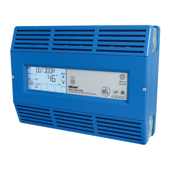
Boiler Control 284
A Flexible Solution for Commercial & Multi-Residential Heating Plants
The Boiler Control 284 is designed to operate up to four
boilers to accurately maintain a target water temperature.
The 284 operates both condensing & non-condensing boilers
that are either modulating, single stage or two stage to
provide a flexible, cost effective mixed boiler plant solution
with better system performance.
The target water temperature is based on outdoor temperature
reset or a fixed setpoint for space or process heating
applications. Additional loads supplied by the 284 include
A Watts Water Technologies Company
Installation & Operation Manual
BACnet is a registered trademark of ASHRAE.
ASHRAE does not endorse, approve or test products
for compliance with ASHRAE standards. Compliance of
listed products to the requirements of ASHRAE Standard
135 is the responsibility of BACnet International (BI).
BTL is a registered trademark of BI.
domestic hot water & fixed setpoint heating. Boiler equal
run-time rotation, stand-by primary pump operation & pump
exercising all increase boiler plant reliability.
The 284 communicates with a Building Automation System
(BAS) using BACnet
& adjustment capability. tekmarNet
Gateway 483 can be added to optimize system performance
& provide remote monitoring capability.
Features
• Outdoor temperature reset
• Programmable schedules
• tekmarNet
compatible
®
• Control up to four boilers
• Condensing & non-condensing boiler groups
• Modulating, single stage or two stage
• Boiler isolation valves
• BACnet
IP or Modbus
®
• Primary pump sequencing
• DHW priority
• Setpoint operation
• Combustion air damper control
• Energy, flow & pressure monitoring
Benefits
• Reduce energy costs
• Prolong equipment life
• Provide boiler redundancy
• Provide primary pump redundancy
• Remote monitoring & adjustment options
• Combine mid & high efficiency boilers to lower
component cost
1 of 60
Multi-Staging
IP or Modbus
for remote monitoring
®
®
Thermostats or a tN4
®
communication
®
© 2016
D 284
05/16
Replaces: 08/14
284_D - 05/16
Advertisement
Table of Contents

Related Manuals for Tekmar 284


Summary of Contents for Tekmar 284
- Page 1 Multi-Staging Replaces: 08/14 A Flexible Solution for Commercial & Multi-Residential Heating Plants The Boiler Control 284 is designed to operate up to four domestic hot water & fixed setpoint heating. Boiler equal boilers to accurately maintain a target water temperature.
-
Page 2: Table Of Contents
Testing the Sensor Wiring ........... 30 Sequence of Operation Boiler (Source (#) Menu) Setup & Operation The 284 is able to operate up to four boilers as a heat source. Boiler Type - ---------------------- ---------------- Each boiler is independently configured allowing for maximum The 284 has four different boiler types to choose from. - Page 3 Modulating Type - - - --- ----------- --------- ------- can be set. This allows the control to properly operate the boilers using either sequential or parallel modulation. Each The MOD TYPE setting selects the analog output signal used boiler typically has a rating plate that specifies the minimum for modulating (MOD) and EMS boiler types.
- Page 4 Boiler’s Maximum Input Signal - 4mA x 100% 16 mA Example: A boiler’s input signal range is 0 to 9 V (dc). The 284 control has an output signal range of 0 to 10 V (dc). Maximum Modulation = x 100% = 90%...
-
Page 5: System Setup
System Setup & Operation Application Mode - - - ----------- ---------- -------- Manual Differential There are five possible application modes that the 284 can be Differential = 10°F (6°C) configured for including: 165°F (74°C) Target + 1/2 Differential • Outdoor Temperature Reset (RSET) Target 160°F (71°C) - Page 6 - -- - - ------- ----------- ---------- - Flow Monitoring Vent Temperature Monitoring & Limiting---------- The control has the capability to monitor flow rate through the The control has the capability to measure & limit the vent connection of a 4-20 mA style flow sensor. Flow is measured in temperature.
-
Page 7: Boiler Plant Operation
Boiler Plant Operation The 284 is able to operate up to four boilers to maintain a boiler setting can be adjusted manually or set to an automatic setting. target temperature. Proportional, Integral & Derivative (PID) logic When the automatic setting is used, the control determines the is used in order to satisfy the boiler target temperature for all best stage delay based on the operation of the system. - Page 8 This setting is applicable for a group of at least two, two-stage Fixed Lead ---------------- ----------------------- condensing boilers. When the boiler plant includes only one boiler group, either a • STG NC (Staging Mode - Two-Stage Non-Condensing condensing or a non-condensing group, a selection must be Boiler Group) made regarding operation of the lead boiler.
- Page 9 The 284 supports operation of a condensing & a non-condensing • Intermittent Heat Call (e.g. external Heat Call interlocked boiler group. A condensing boiler group is created when at least with space heating thermostat) one boiler is selected to be condensing & a non-condensing...
-
Page 10: Outdoor Temperature Reset Operation
Outdoor Temperature Reset Operation Outdoor Temperature Reset is available by setting the Terminal Unit ---------------- --------------------- Application Mode in the Setup Menu to RSET. Select the appropriate terminal unit in the Setup Menu. This will change the shape of the characterized heating curve In a heating system, the rate of heat supplied to the building to better match the heat transfer properties of that specific must equal the rate at which heat is lost. - Page 11 Radiator (RAD) Room ---- --------------------- ------------------- A radiator terminal unit has a large heated surface that is The Room setting is the desired room air temperature, according exposed to the room. A radiator provides heat to the room to the outdoor reset heating curve. The Room setting parallel through radiant heat transfer &...
-
Page 12: Setpoint Operation
Setpoint Operation Setpoint operation is dependent on the application mode setting. Primary Pump During Setpoint - -- - - - - - -- - - - - - -- - This setting selects whether or not primary pump operation is •... -
Page 13: Energy Management System (Ems) Operation
Priority Override - - ------ ---------- ----------- ---- Conditional Setpoint Priority -------- ------------- Priority Override applies when Setpoint Priority is set to ON. It If the boiler supply temperature is maintained at or above the prevents the building from cooling off too much or the possibility required temperature during setpoint heating, this indicates of a potential freeze up during setpoint priority. -
Page 14: Indirect Domestic Hot Water (Idhw) Operation
CONVERSION TABLE 2 - 10 Example Range = 0 - 10 V (dc) 4 - 20 mA* 2 - 10 V (dc) Boiler Target Input = 7 V (dc) 157°F (69°C) – – – (OFF) Offset = +5°F (3°C) +5°F (3°C) 50°F (10.0°C) Boiler Target = 162°F (72°C) - Page 15 IDHW Mode -- ----- ----------------------- ------- Primary Pump During IDHW --------------------------------------- The control has a IDHW MODE setting that selects whether The control has a Primary Pump during IDHW setting that or not indirect DHW operation is active. selects whether or not the primary pump is required during indirect DHW operation.
- Page 16 For non-tN4 space heating, the primary pump shuts off to IDHW Mixing Purge ---------- --------------------- provide priority. If the primary pump is required to operate for After IDHW operation, the boiler is extremely hot. At the same IDHW, priority requires the use of an external relay to force time, the heating zones may have cooled off considerably after the heating zones off.
-
Page 17: Dedicated Domestic Hot Water (Ddhw) Operation
Dedicated Domestic Hot Water (DDHW) Operation The control can operate to provide heat for a Dedicated DDHW Differential ---------- ---------------------- Domestic Hot Water (DDHW) system. A DHW Call is registered when the temperature at the DHW DDHW heating is available by setting the Application Mode in sensor drops the DDHW DIFF setting below the DDHW Setpoint the Setup Menu to DDHW. -
Page 18: Pump Operation
Pump Operation Primary Pump Operation ----- ----------- --------- A flow proof call can be provided in two ways: The control includes two primary pump outputs with capability Contact Closure for sequencing. There is pump enable setting for each primary A dry contact or 24 V (ac) signal is applied across the Flow pump in the Setup menu. - Page 19 Stand-by Pump Operation is fixed at 4 seconds. For isolation valves, the time is always fixed at 30 seconds. Failed The control includes a boiler post-purge feature that operates the respective pump / valve for a period of time after the boiler is turned off.
-
Page 20: Damper & Dhw Recirculation
Proof Call terminals 3 & 4. Setting the Schedule To provide greater energy savings, you can operate the The 284 Setback /Off DIP Switch must be set to Setback control on a programmable schedule. The schedule is stored to access the Schedule Menu. -
Page 21: Time Clock
DHW heating of the zones must operate based on the same cycle. In order to Permanent Unoccupied do this, the 284 listens to all of the cycle length requests from Occupied or Schedule all of the tekmarNet 4 Thermostats. The 284 then determines ®... -
Page 22: Installation
It is your responsibility to ensure that this control is safely installed according to all applicable codes and standards. tekmar is not responsible for damages resulting from improper installation and/or maintenance. To avoid serious personal injury and damage to the equipment: •... -
Page 23: Control Wiring
Control Wiring This section explains how to wire individual devices to the Boiler Control 284. For step by step wiring refer to the terminal number on the right of the page. • Before wiring, ensure all power is turned off & take all •... - Page 24 Terminals 1, 2 The 284 requires a closed switch or short for proof of flow. Up to 24 V (ac) can be passed through the switch. If a flow proof device is being used, ensure the External Flow Proof / Off DIP switch on the front of the control is set to the External Flow Proof position.
- Page 25 Wiring a Heat Call Terminals 5, 6 The 284 requires a switched external heat call to operate the boiler plant unless calls for heat are generated through a tekmarNet device, EMS, BACnet or Modbus connection. The heat call can be volt free or up to 24 V (ac).
-
Page 26: Sensor Installation & Wiring
Stage 1 Stage 2 • Connect the Mod + terminals from boilers 1, 2, 3 and 4 to the 284 terminals 51, 57, 63 and 69, respectively. • Connect the Mod - terminals from boilers 1, 2, 3 and 4 to the 284 terminals 52, 58, 64 and 70, respectively. - Page 27 Terminals 26 to 31 Up to 4 boiler outlet sensors can be wired to the 284. These connections are not polarity sensitive. • Connect one wire from the outlet sensor for boiler 1 to the Boil 1 Out terminal 26.
- Page 28 Wiring a Flow Sensor Terminals 11, 12 An analog flow sensor can be connected to the 284 to provide flow monitoring. The control supports a 4-20 mA style sensor. Examples of compatible aftermarket flow sensors include the Kele SDI series, 2200 &...
-
Page 29: Ems, Modbus ® & Bacnet ® Connections
Wiring a Vent Sensor Terminals 23, 25 A vent sensor can be connected to the 284 to provide monitoring of the common boiler plant exhaust vent temperature. Compatible sensors include a 10K ohm NTC curve J thermistor. The control is capable of displaying temperatures up °... -
Page 30: Wiring The Tekmarnet ® Devices
Wiring the tekmarNet Devices ® tN4 Boiler Bus b Terminals 32 - 33 Terminals 32 & 33 provide communication for tN4 devices on the tN4 Boiler Bus b. Connect terminals 32 (tN4) & 33 (C0) to the corresponding terminals on the tN4 devices that are to be connected. The connection is polarity sensitive. -
Page 31: Testing The Control Wiring
Testing the Control Wiring Testing the Power Terminals 83 & 84 If the control display does not turn on, check the Power In L & N terminals (83 & 84) using an electrical multimeter. The voltage should measure between 103.5 to 126.5 V (ac). User Test (HAND) Manual Override Button The User Test (HAND mode) is one of the Manual Override... - Page 32 Testing the Heat Call Terminals 5 & 6 Set the Application Mode to RSET. Remove all wires from short circuit or 24 V (ac) over the Heat Call terminals. The the Heat Call terminals (5 & 6). The control display should control should now show a Heat Call.
-
Page 33: Control Settings
Lock / Unlock & Access Levels Unlocked Use this DIP switch to lock & unlock the Access Level of the 284 & all connected tN4 devices, including tN4 thermostats. For details, see above. • Once unlocked, the access level can be changed in the Toolbox menu. -
Page 34: User Interface
• Single stage: 100% (On) • Two stage: 50% (stage 1 On), 100% tekmarNet ® (stage 2 On) The 284 is communicating with other • Modulating: current modulation % tekmarNet devices. ® • EMS = current setpoint temperature... -
Page 35: Navigating The Display
Navigating The Display The menu items of the 284 are described in detail in the following pages. The number of available items changes depending on the control configuration. To find out what other settings affect the display of an item, refer to the menu descriptions. - Page 36 View Menu (2 of 2) Item Field Range Description DEDICATED DHW ---, -22 to 266°F Current dedicated DHW tank temperature as measured by the DHW sensor. “----” is (-30.0 to 130.0°C) displayed if there is a sensor fault. Access: User This item is only available if Application Mode is set to DDHW.
-
Page 37: Setup Menu
Setup Menu (1 of 6) Setup Menu items are used for system specific configuration. Item Field Range Description APPLICATION MODE RSET, SETP, DDHW, RSET = Outdoor Temperature Reset EMS, BAS SETP = Setpoint Heating Default = RSET DDHW = Dedicated DHW Heating EMS = Energy Management System Access: INST BAS = Building Automation System... - Page 38 Setup Menu (2 of 6) Item Field Range Description BOILER MINIMUM OFF, 60 to 180°F The minimum allowed boiler target temperature used for the non-condensing (OFF, 15.5 to 82.0°C) boiler group. Check the boiler manufacturer’s manual for recommended minimum Default: 140°F (60.0°C) boiler supply temperatures.
- Page 39 Setup Menu (3 of 6) Item Field Range Description CA DELAY OFF, 0:10 to 3:00 min The time delay for the first boiler to operate once the C.A. damper (Aux) relay Default: 1:00 min turns on. This item is only available if the External C.A. Proof / Off switch is set to Off & Access: ADV Auxiliary Relay is set to DMPR.
- Page 40 Setup Menu (4 of 6) Item Field Range Description FIXED LAST OFF or ON Selects whether or not the last boiler is to be excluded from the rotation sequence. Default: OFF If set to ON, boiler 4 is always the last to fire. This item is only available if boiler 4 is enabled (Boiler Enable = AUTO) &...
- Page 41 Setup Menu (5 of 6) Item Field Range Description OFF or ON INDIRECT DHW PRIORITY Selects whether indirect DHW priority is active or not. Default: OFF This item is only available when Application Mode is set to RSET or EMS & Indirect Access: ADV DHW Mode is set to ON.
- Page 42 Setup Menu (6 of 6) Item Field Range Description 2 to 10°F DEDICATED DHW DIFFERENTIAL (1.0 to 5.5°C) The temperature differential of the dedicated DHW tank from the DDHW SETPOINT Default: 5°F (3.0°C) settings. This item is only available when Application Mode is set to DDHW. Access: ADV PRIORITY OVERRIDE OFF, AUTO, 0:20 to...
-
Page 43: Source # Menu
Source # Menu (1 of 2) There is a different Source Menu for each of the 4 boilers that the 284 can operate. Settings can vary for each boiler if desired. OFF or AUTO Default: BOILER ENABLE AUTO for Boil1 Selects whether the boiler is operational or not. - Page 44 Source # Menu (2 of 2) MOTOR SPEED 10 to 230 sec The amount of time required for the modulating actuating motor to fully open the Default: 30 sec gas valve or operate the blower from a stopped position to full speed. This item is only available if Boiler Enable is set to AUTO, Boiler 1 Copy is set to Access: ADV OFF &...
-
Page 45: Bas Menu
BAS Menu (1 of 2) Configure Modbus & BACnet options. ® ® Item Field Range Description BAS MONITOR OFF or ON Selects whether or not BAS monitor mode is to be used. Monitor mode allows for Default: OFF read / write capability of select menu items. This item is only available when Application Mode is set to either RSET, SETP, Access: ADV DDHW or EMS. - Page 46 BAS Menu (2 of 2) Item Field Range Description BACNET GATEWAY Sets the Gateway address on the BACnet network. The address is set using four 0 to 255, 0 to 255, 0 to ® number sets displayed in the source output fields. Touch the ‘Next Item’ button to 255, 1 to 254 view &...
-
Page 47: Monitor # Menu
Monitor # Menu (1 of 1) Monitor (#) items are repeated for each available boiler. Item Field Range Description BURNER RUN TIME 0 to 65535 hours The total running time of the boiler since this item was last cleared. Press & hold the ‘CLEAR’... -
Page 48: Monitor Menu
Monitor Menu (1 of 2) This Monitor Menu displays items that are not specific to one boiler. Item Field Range Description ENERGY 0 to 65535 Therms Total calculated energy being delivered to the load since this item was last cleared. Press &... - Page 49 Monitor Menu (2 of 2) Item Field Range Description -22 to 266°F BOILER INLET HIGH Records the highest boiler inlet temperature since this item was last cleared. (-30.0 to 130.0°C) Press & hold the ‘CLEAR’ button while viewing to reset. Access: ADV This item is only available when a boiler inlet sensor is connected.
-
Page 50: Time Menu
Time Menu (1 of 1) The Time menu sets the time & date. The Setback / Off switch setting must be in the Setback position in order to have access to the Time menu. Set hours, then select AM or Set minutes. -
Page 51: Schedule Menu
Schedule Menu (1 of 1) Schedule Type The 284 can follow an internal schedule or an available 24 Hour 5-11 7 day schedule on a tekmarNet network. Four heating schedules ® can be present on one network. The number of available •... -
Page 52: Toolbox Menu
Press the Enter button to show SEL. After 3 seconds DONE will be indicated & factory defaults will be loaded to all settings. Access: ADV TYPE & SOFTWARE VERSION 284, Software Version Product number of the control displayed in the number field. Software version Access: USER displayed in the item field. - Page 53 Toolbox Menu (2 of 2) Item Field Range Description BOILER BUS 3 DEVICES 1 to 24 Displays the number of tN4 devices connected to the Boiler Bus 3 terminals, tN4 Access: INST & C3 (38 & 39). The error date & the ERROR HISTORY 1-5 type of error Displays a history of any past errors that have occurred on the system.
-
Page 54: Manual Override
Manual Override Commissioning, testing & troubleshooting features of the 284 Hand Override (HAND) ----------- ---------------- are accessed by holding the Manual Override button for 3 In this mode, the control overrides the normal operating mode seconds. Once an item is selected in this menu, there is a 3 &... - Page 55 Selecting a Manual Override Mode Once an item is selected in this menu, there is a 3 second delay before Press & the feature activates. hold for 3 Manual seconds Override Item Field Range Description AUTO, OFF, HAND, MANUAL OVERRIDE MAX, PURG Select which mode of manual override to activate.
-
Page 56: Troubleshooting
Troubleshooting It is recommended to complete all wiring to ensure trouble free operation. Should an error occur, simply follow these steps: 1. Find: If the Boiler Control 284 flashes on the screen, it is indicating a problem on the system. - Page 57 Error Messages (2 of 3) Error Message Description Troubleshooting Tips BOILER (#) OUTLET SENSOR MAXIMUM EXCEEDED The boiler outlet (#) temperature exceeded the Maximum Outlet BOILER (#) OUTLET TEMP temperature. As a result, the control stops operation for the EXCEEDS MAX OUT SETTING associated boiler.
- Page 58 More than one tN4 system control has been detected on the tN4 DUPLICATE MASTER CONTROL Boiler Bus. The 284 is a “Master Device” & no other tekmarNet DETECTED ON TN4 BUS reset controls can be added to the tN4 Boiler Bus terminals. If one has been added it must be removed from the system.
- Page 59 Notes 59 of 60 A Watts Water Technologies Company © 2016 284_D - 05/16...
-
Page 60: Technical Data
& other contact informa- tion regarding the appropriate Representative. tekmar Control Systems Ltd., A Watts Water Technologies Company. Head Office: 5100 Silver Star Road, Vernon, B.C. Canada V1B 3K4, 250-545-7749, Fax. 250-984-0815 Web Site: tekmarControls.com 60 of 60 Product design, software &...
Need help?
Do you have a question about the 284 and is the answer not in the manual?
Questions and answers