Table of Contents
Advertisement
- Data Brochure
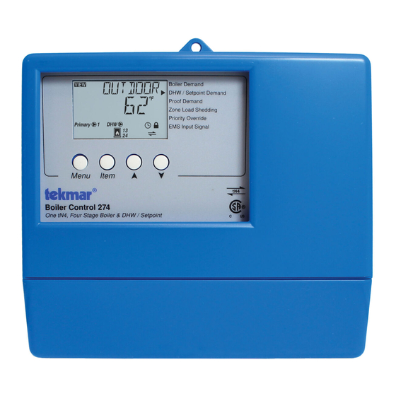
Boiler Control 274
The Boiler Control 274 operates up to four on/off boilers to provide outdoor reset operation, domestic hot water and setpoint
operation with priority. When operating as a tN4 System Control, the 274 can connect with up to 24 tN4 devices on a single
boiler bus. The 274 has primary pump sequencing capabilities along with a flow proof or combustion air damper proof
demand.
Additional functions include:
•
tN4 Compatible
•
24 Hour, 5-1-1, 7 Day Schedule
•
Flow or Combustion Air Proof
•
Four On/Off Boilers
•
Equal Run Time Rotation
Boiler Control 274
One tN4, Four Stage Boiler & DHW / Setpoint
1
tN4
tN4
Boiler
Bus
Input
Outdoor Sensor
Included
OR
0-10 or 2-10 V (dc)
from EMS
Input
Input
Universal
Universal
Sensor
Sensor
Included
Included
VIEW
Primary
1
DHW
13
24
Menu
Item
Do not apply power
2
3
4
5
6
Com
Out
Boil
Com
BRet/
+
–
Sup
DHW
Output
Up to 2
Boiler Pumps
OR
Output
Up to 4
On/Off Boilers
•
Primary Pump Sequencing
•
DHW Operation
•
Optional DHW Sensor
•
Setpoint Operation
Boiler Demand
DHW / Setpoint Demand
Demands
Proof Demand
Zone Load Shedding
Priority Override
EMS Input Signal
Modes
1 Up to 4 On/Off Boilers
2 Up to 2 On/Off Boilers & 2 Pumps
3 Up to 2 Lo/Hi Boilers
4 1 Lo/Hi Boiler & 1 Pump
5 1 Three Stage Boiler & Pump
6 1 Four Stage Boiler
Made in Canada by
tekmar Control Systems Ltd
tektra 1020-02
Power
Relays
Demands
Signal wiring must be rated at least 300 V.
7
8
9
10
11
12
13
14
15
16
17
Relay
Relay
Relay
Relay
C.A. /
DHW
1
2
3
4
Alert
/ P2
OR
Output
Output
Combustion
DHW Pump
Air Damper
OR
OR Alert
Primary Pump
1 of 44
Setback
Rotate
Pump Sequencer
Fixed Last
Off
Fixed Lead
EMS
First On / Last Off
First On / First Off
Off
Exercise
Test
off
not testing
red
testing
red
testing paused
For maximum heat,
press and hold Test
button for 3 seconds.
Meets Class B:
Canadian ICES
FCC Part 15
115 V ±10% 60 Hz 7 VA, 1150 VA max.
230 V (ac) 5 A 1/3 hp
20 to 260 V (ac) 2 VA
18
19
20
21
22
23
24
25
Prim
Power
Boiler
DHW
Com
Pr.
P1
L
N
Demand
/Setp
Dem
Dem
Output
Input
Primary
115 V (ac)
Pump
Power Supply
© 2012
274_D
11/12
Input
Flow OR
C.A. Proof
Input
DHW OR
Setpoint
Demand
Signal
Input
Boiler
Demand
Signal
274_D - 11/12
Advertisement
Table of Contents

Related Manuals for Tekmar 274


Summary of Contents for Tekmar 274
- Page 1 The Boiler Control 274 operates up to four on/off boilers to provide outdoor reset operation, domestic hot water and setpoint operation with priority. When operating as a tN4 System Control, the 274 can connect with up to 24 tN4 devices on a single boiler bus.
-
Page 2: Table Of Contents
How to Use the Data Brochure This brochure is organized into three main sections. The Control Settings section of this brochure describes the various items that are adjusted and displayed by the They are: 1) Sequence of Operation, control. The control functions of each adjustable item are 2) Installation, described in the Sequence of Operation. -
Page 3: Display And Symbol Description
Displays when the combustion air damper relay is closed operating LOCK SCHEDULE MASTER Displays when adjusting Access level if Displays when the 274 is a schedule Switch is set to lock. master WARM WEATHER SHUT DOWN WARNING Displays when the control is in warm Displays when an error exists. -
Page 4: Access Level
Access Level The access level restricts the number of Menus, Items, • Installer (INST): Select this access level to limit some of the settings available to the installer. This is the factory and Adjustments that can be accessed by the user. The default access level. - Page 5 Terminal Unit Setting in Adjust Menu Radiator (RAD) A radiator terminal unit has a large heated surface that is Select the appropriate terminal unit in the adjust menu. exposed to the room. A radiator provides heat to the room This will change the shape of the characterized heating through radiant heat transfer and natural convection.
-
Page 6: Section C: Boiler Operation
70°F (21.0°C). This setting establishes the Demand is present. beginning of the boiler characterized heating curve. Boiler Operation Section C The 274 is able to operate up to four on/off boilers as a heat Relay 1 Relay 2 Relay3 Relay 4 source. - Page 7 Boiler Minimum Setting in Adjust Menu The MED setting is selected if the boiler that is used has The boiler minimum is the lowest temperature that the a medium thermal mass. This means that the boiler either control is allowed to use as a boiler target temperature. has a large water content and a low metal content or a During mild conditions, if the control calculates a boiler low water content and a high metal content.
-
Page 8: Section D: Combustion Air And Alert Settings
Fixed Lead & First On / First Off Manual Differential Differential = 10°F (6°C) In some applications, it may be desirable to have the first 165°F (74°C) Target + 1/2 Differential boiler fire first at all times while the firing sequence of the Target 160°F (71°C) remaining boilers is changed using Equal Run Time Rotation. -
Page 9: Section E: Domestic Hot Water Operation
The DHW Sensor must be set to On. There cannot be DHW Demand is applied while the DHW sensor is enabled an externally powered DHW demand when using a DHW in the 274, an error message is generated and both demands sensor. are ignored. - Page 10 DHW Differential Setting in Adjust Menu Mode OFF / No DHW Generation All DHW demands are ignored. If this mode is selected while Due to large differences between the heating load and the DHW generation is underway, all DHW operation stops. DHW load, a separate DHW differential should be used whenever a DHW Demand is present.
- Page 11 Mode 3 - DHW in Primary/Secondary with No Priority Mode 5 - DHW in Parallel / Last Boiler with Priority When a valid DHW Demand is present, the DHW relay When a valid DHW Demand is present, the DHW relay (terminal 17) and Primary Pump relay (terminal 18) turn (terminal 17) turns on and boiler pump 4 turns off.
- Page 12 DHW Priority Override Setting in Adjust Menu DHW Mixing Purge DHW Priority Override applies to DHW MODE 2 and 4, as After DHW operation, the boiler is extremely hot. At the same well as Mode 5 if there is a tN4 device with DHW. It prevents time, the heating zones may have cooled off considerably the building from cooling off too much or the possibility of after being off for a period of time.
-
Page 13: Section F: Setpoint Operation
A demand from a tN4 Setpoint Control can coexist with another setpoint demand without generating an error message. The Primary Pump 274 will then use the higher of the two targets. Boiler Target Temperature during a Setpoint Demand Mode 2 Setpoint in Parallel with Priority... - Page 14 Automatic Priority Override Mode 3 Setpoint in Primary/Secondary with No Priority Whenever a Setpoint Demand is present, the primary pump 2 hours is turned on and the boilers are operated to maintain the setpoint target. Mode = 3 Setpoint 15 mins Primary 70°F (21°C) Design Temperature...
-
Page 15: Section G: Energy Management System (Ems)
Energy Management System (EMS) Section G The control can accept an external DC signal from an Energy CONVERSION TABLE 0 - 10 Management System (EMS) in place of the outdoor sensor. 0 - 20 mA* 0 - 10 V (dc) Boiler Target The control converts the DC signal into the appropriate –... -
Page 16: Section H: Pump Operation
Pump Operation Section H Primary Pump Operation Stand-by Operation The control includes two primary pump outputs with The control only operates one primary pump at a time. A capability for sequencing. Primary pump sequencing is flow proof device can be used to detect when stand-by activated through a DIP switch. -
Page 17: Section I: Exercising
Flow Proof Delay Setting in Adjust Menu Primary Pump Purge The control waits a period of time to receive a flow proof After the last valid demand is removed, the primary pump demand from the time the primary pump turns on. If the is operated for an additional purging time of at least 20 control does not receive a flow proof demand within that seconds. -
Page 18: Section K: Setting The Schedule
(MST) 1 to 4. After a master schedule is selected, a clock symbol will appear in the View menu display. Schedule Mode Note: The 274 Setback /Off DIP Switch must be set to Setback to access the Schedule Menu. The schedule mode can have either 4 or 2 events per day. -
Page 19: Section M: Tekmarnet ® 4 Communication
In order to operate the system as efficiently as possible, all of the zones must operate based on the same cycle. In order to do this, the 274 listens to all of the cycle length requests from all of the tekmarNet ®... -
Page 20: Installation
One Boiler Control 274, One Outdoor Sensor 070, Two Universal Sensors 082, One 500 Ohm resistor, Data Brochures D 274, D 070, D 001, Application Brochure A 274. Step Two — Mounting the Base Remove the control from its base by pressing on the release clip in the wiring chamber and sliding the control away from it. - Page 21 Boiler Demand To generate a Boiler Demand, a voltage between 20 V (ac) Boiler Demand and 260 V (ac) must be applied across the Boiler Demand terminals (21 and 22). 20 to 260 DHW Demand V (ac) To generate a DHW Demand, a voltage between 20 V (ac) and 260 V (ac) must be applied across the DHW/Setp and Com Dem terminals (23 and 24).
- Page 22 Sensor is used by the control to measure the boiler supply Boiler Supply Sensor 082 water temperature. DHW or Boiler Return Sensor (tekmar 082) Connect the two wires from the DHW Sensor 082 to the Com and BRet / DHW (5 and 6) terminals. The DHW Sensor is used by the control to measure the DHW water temperature or the DHW Exchange Supply Temperature.
- Page 23 Relay Relay Relay Relay Wiring the Boiler Pumps (RELAY TYPE = Boiler pump Terminals 7-8, 9-10, 11-12 and 13-14 are dry contacts. No power is available from these terminals. These contacts can be used to turn on individual boiler pumps. Wire line Boiler voltage to one side of the relay.
- Page 24 Terminals 2 – 6 Testing tekmar Sensors To test the sensors, the actual temperature at each sensor • Disconnect each sensor from the control. location must be measured. • Test the sensors resistance according to the instructions in the sensor Data Brochure D 070.
-
Page 25: Control Settings
Set the EMS / Demands DIP switch to Demands if the control is accepting a boiler demand and using the outdoor • If the 274 is to be a schedule member or schedule master, set the DIP switch to Setback to enable the Time and sensor for outdoor reset. - Page 26 Rotate / Off Fixed Lead / Off Use the Rotate / Off DIP switch to enable the Equal Run • Use the Fixed Lead / Off DIP switch to exclude the first boiler in the rotation sequence. This DIP is only active Time Rotation feature.
-
Page 27: View Menu
Display Menus View Menu (1 of 2) The View menu items display the current operating temperatures and status information of the system. Item Field Range Access Description VIEW OUTDOOR USER Current outdoor air temperature as measured by -76 to 149°F INST the outdoor sensor. - Page 28 View Menu (2 of 2) Item Field Range Access Description BOILER 2 RUNNING TIME SECTION C VIEW The total running time of Boiler 2 since this item was last cleared. To clear this item, press the Up and 0 to 9999 hours Down buttons simultaneously while viewing this item.
-
Page 29: Adjust Menu
Adjust Menu (1 of 6) The Adjust Menu items are the programmable settings used to operate the mechanical equipment. Item Field Range Access Description Actual Setting 1 (4 On/Off) 2 (2 On/Off & Pumps) ADJUST 3 (2 Lo/Hi) MODE SECTION C Selects the control mode of operation. - Page 30 Adjust Menu (2 of 6) Item Field Range Access Description Actual Setting CP1, Au (Auto), BOILER 2 SECTION C ADJUST INST Selects Whether Boiler 2 is operational or not. CP1 copies the settings of boiler 1 to boiler 2. Default = Au CP1, Au (Auto), BOILER 3 SECTION C...
- Page 31 Adjust Menu (3 of 6) Item Field Range Access Description Actual Setting Au (Auto), 2 to BOILER DIFFERENTIAL SECTION C 42°F ADJUST The temperature differential that the control is (Au, 1 to to use to cycle the boiler On and Off (half above 23.5°C) and half below target).
- Page 32 Adjust Menu (4 of 6) Item Field Range Access Description Actual Setting BOILER 1 MASS SECTION C ADJUST Lo, Med, Hi INST The thermal mass characteristics of the boiler. Default = Med Note: This item is only available when Boiler 1 is set to Au. BOILER PUMP 1 PURGE SECTION H OFF, 0:10 to...
- Page 33 Adjust Menu (5 of 6) Item Field Range Access Description Actual Setting DHW DIFFERENTIAL SECTION E The temperature differential (swing up and 1 to 42°F ADJUST down) of the DHW tank from the DHW setting. (0.5 to 23.5°C) Note: This item is only available when DHW Default = 6°F Mode is set to either 1, 2, 3, 4 or 6 AND the DHW (3.0°C)
- Page 34 Adjust Menu (6 of 6) Item Field Range Access Description Actual Setting ZONE LOAD SHEDDING SECTION M Selects whether Zone Load Shedding is active ADJUST OFF, On or not. Default = On Note: This item is only available when a tN4 device is present and Boil Min is set between 80 to 180°F (26.5 to 82.0°C).
-
Page 35: Time Menu
Time Menu (1 of 2) Note: The Setback / Off switch setting must be in the Setback position in order to have access to the TIME menu. The Time menu items set the time clock, day and date. Item Field Range Access Description... -
Page 36: Schedule Menu
Time Menu (2 of 2) Item Field Range Access Description YEAR SECTION J TIME 2000 ... 2255 INST Set the current year. Default = 2005 Note: This item is only available when Daylight Savings Time is set to Mode 1 or 2. TIME MODE SECTION J... - Page 37 Schedule Menu (2 of 3) Item Field Range Access Description – –:– – to 11:50 PM SCHD ALL DAYS OF THE WEEK SECTION K Wake UnOcc Sleep – –:– – to 23:50 Select the times for the scheduled events. USER INST Note: This item is only available when the Heat Schedule is set to CTRL or MST1 to MST4 AND the...
- Page 38 Schedule Menu (3 of 3) Item Field Range Access Description – –:– – to 11:50 PM SCHD MONDAY SECTION K Wake UnOcc Sleep – –:– – to 23:50 Select the times for the scheduled events. USER Note: This item is only available when the Heat INST Schedule is set to CTRL or MST1 to MST4 AND the Default = 6:00 AM...
-
Page 39: Misc Menu
DEFAULT SEL and load the default Default = OFF settings. USER TYPE 274, Software Version INST Product number of this control. Hold the Up button MISC to view the software version. After the last item, the control returns to the first item in the menu. -
Page 40: Testing The Control
Testing the Control Step 7 The DHW relay is closed. The C.A. / Alert relay is opened. The control has a built-in test routine that tests the main The primary pump is turned off. control functions. The control continually monitors the The control exits the test sequence. -
Page 41: Error Messages
To Enable Zone Test: 4. Pressing the Up button will turn off stage 1, and turn on stage 2 of the same device (if that device has a second 1. Press and hold the Test button for more than 6 seconds. stage) or turn on stage 1 of the device with the next lowest The control displays ZONE TEST OFF and the Test LED address. - Page 42 Error Messages (2 of 3) Error Message Description VIEW SCHEDULE MASTER ERROR More than one tN4 device has been assigned the same master number. BOILER SUPPLY SENSOR SHORT CIRCUIT VIEW Due to a short circuit, the control failed to read the boiler supply sensor. When there is a call for heat, the control no longer controls the boiler(s).
- Page 43 Error Messages (3 of 3) Error Message Description VIEW PRIMARY PUMP P1 & P2 FAILURE Both the primary pump P1 and P2 have failed. VIEW PRIMARY PUMP P1 FAILURE The primary pump P1 has failed. The Prim P1 relay closed, but a flow proof demand was not detected before the proof demand delay time elapsed.
-
Page 44: Technical Data
Representative. tekmar Control Systems Ltd., A Watts Water Technologies Company. Head Offi ce: 5100 Silver Star Road, Vernon, B.C. Canada V1B 3K4, 250-545-7749, Fax. 250-545-0650 Web Site: www.tekmarControls.com 44 of 44 Product design, software and literature are Copyright ©2012 by...
Need help?
Do you have a question about the 274 and is the answer not in the manual?
Questions and answers