Table of Contents
Advertisement
Quick Links
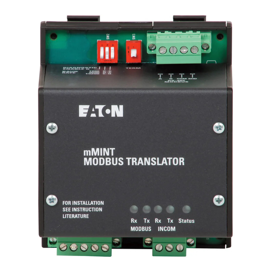
Figure 1: The mMINT Module
CONTENTS
Description
1.0
GENERAL DESCRIPTION......................................................... 2
2.0
FEATURES ................................................................................ 2
3.0
INSTALLATION .......................................................................... 2
3.1
Module Mounting........................................................2
3.2
Simplified Wiring Rules ..............................................2
3.2.1
INCOM Network ...............................................2
3.2.2
Modbus RS485 Network...................................3
4.0
mMINT MODULE CONNECTIONS............................................ 3
4.1
Power Connections ....................................................3
4.2
INCOM Connections ..................................................3
4.3
Modbus Connections .................................................3
5.0
SWITCHES AND INDICATOR LEDS......................................... 4
5.1
Modbus RS485 Network Rx LED [Green] ..................4
5.2
Modbus RS485 Network Tx LED [Green] ..................4
5.3
INCOM Network Rx LED [Green]...............................4
5.4
INCOM Network Tx LED [Green] ...............................4
5.5
Status LED [Green] ....................................................4
INCOM 100 Ω Termination Dip Switch (SW1)............4
5.6
5.7
Modbus RS485 Baud Rate Dip Switch (SW2) ...........4
5.8
Unique mMINT Address (SW2)..................................4
Modbus 121 Ω Termination Dip Switch (SW3)...........5
5.9
6.0
NETWORK COMMUNICATION PROTOCOLS ......................... 5
6.1
Overview ....................................................................5
Effective September 2003
Instructions for mMINT
- Modbus
Translator Module -
®
Installation and Use
6.2
Function Codes.......................................................... 5
6.3
Block of Registers ...................................................... 5
6.4
Register Access Configurations................................. 5
6.5
INCOM Routing Address Configurations ................... 6
6.6
Command/Data Pass Through .................................. 6
6.7
Control of INCOM Product ......................................... 6
6.8
Energy Format ........................................................... 7
6.9
Supported Diagnostic Sub-Functions......................... 8
6.10 Exception Codes........................................................ 8
7.0
Troubleshooting ..........................................................................9
APPENDIX A .........................................................................................9
Notes ...................................................................................................19
TERMS AND CONDITIONS................................................................19
Figures
Figure 1: The mMINT Module ................................................. 1
Figure 2: mMINT in a Communications Network..................... 2
Figure 3: Connections ............................................................. 3
Figure 4: Indicators ................................................................. 4
Figure 5: Switches.................................................................... 4
Format ............................................................................ 6
Format ............................................................................ 7
Figure 8: Control To INCOM Product Data Format ................. 7
Figure 9: 4-Register Energy Data Format ............................... 8
Tables
Table 1: Power Connector Pin Outs........................................ 3
Table 2: INCOM Connector Pin Outs ...................................... 3
Table 3: Modbus RS485 Connector Pin Outs ......................... 3
Table 4: RS485 Baud Rate Switches (Normal) ....................... 4
Table 5: RS485 Baud Rate Switches (Diagnostics) ................ 5
Table 6: Diagnostic Sub Function Numbers ............................ 8
Table 8: Modbus Register Map (in Functional Order) ........... 12
Table 9: Primary Status Code Definitions ............................. 14
Table 10: Secondary Status Code Definitions....................... 14
Table 11: Cause - of - Status Code Definitions..................... 15
Table 12: Control 'Slave Action Number' Definitions ............. 17
Table 13: mMINT Configuration Registers. ........................... 18
I.L. 66A7508H05
Page 1
Advertisement
Table of Contents

Related Manuals for Eaton Cutler-Hammer Modbus mMINT


Summary of Contents for Eaton Cutler-Hammer Modbus mMINT
-
Page 1: Table Of Contents
I.L. 66A7508H05 Page 1 Instructions for mMINT - Modbus Translator Module - ® Installation and Use Function Codes............5 Block of Registers ............5 Register Access Configurations......... 5 INCOM Routing Address Configurations ....6 Command/Data Pass Through ........6 Control of INCOM Product ......... 6 Energy Format ............ -
Page 2: General Description
I.L. 66A7508H05 Page 2 1.0 GENERAL DESCRIPTION WARNING The mMINT (Modbus Master INCOM Network Translator) ATTEMPT INSTALL PERFORM Module, as seen in Figure 1, is a Cutler-Hammer accessory MAINTENANCE ON EQUIPMENT WHILE IT IS ENERGIZED. product that will provide communication between a Modbus DEATH OR SEVERE PERSONAL INJURY CAN RESULT RTU network and an INCOM (INdustrial COMmunications) FROM... -
Page 3: Modbus Rs485 Network
I.L. 66A7508H05 Page 3 • Recommended INCOM cable styles are Belden 9463 or C-H style 2A957805G01. • The maximum system capacity is 10,000 feet of communications cable and 32 slave devices on the INCOM network under the mMINT. • Non-terminated taps, up to 200 feet in length, off the main link are permitted, but add to the total cable length. -
Page 4: Switches And Indicator Leds
I.L. 66A7508H05 Page 4 RS485 Network-A is the non-inverting differential connection This indicator will be flashing whenever the module is powered for the Modbus RTU network. RS485 Network-B is the up and the microcontroller is executing instructions. The inverting differential connection for the Modbus RTU network. flashing rate is approximately 1 second ON / 1 second OFF. -
Page 5: Modbus 121 Ω Termination Dip Switch (Sw3)
Data pertaining to the objects configured in the block of IL17384 - Part A: IMPACC Communications Standard, assignment registers is mapped into registers starting at EATON, Cutler-Hammer. Specific product profiles are located 41201/420737 (04B0 /5100 ) and continuing in successive in the other Part sections. -
Page 6: Incom Routing Address Configurations
I.L. 66A7508H05 Page 6 When passing a command or data through to an INCOM Non-volatile register 42002/425347 (07D1 /6302 ) is used to product, the mMINT acts as a dumb slave. Without configure 32-bit fixed point and 64-bit energy word order. modification, it passes the command or data through to the When non-zero (factory default), the fixed point and energy low INCOM product. -
Page 7: Energy Format
I.L. 66A7508H05 Page 7 A set of registers is reserved for the control protocol. They If the 'slave action number' and its 1's complement are valid, begin at register 42901/425089 (0B54 /6200 ) and extend the mMINT issues the 'slave action' control command onto the through 42903/425091 (0B56 /6202 ). -
Page 8: Supported Diagnostic Sub-Functions
I.L. 66A7508H05 Page 8 Register 3 high byte contains a value corresponding to 6.10 Exception Codes Engineering Units (power of 10 signed exponent). Register 3 low byte contains a Mantissa Multiplier value (power of 2 Under certain circumstances, the mMINT will return an signed exponent). -
Page 9: Troubleshooting
I.L. 66A7508H05 Page 9 7.0 Troubleshooting APPENDIX A The most common issues experienced with the installation of Notes: an mMINT module are addressed below. ® Modbus is a registered trademark of Schneider If you have any questions or need further information or Electric. -
Page 10: Table 7: Modbus Register Map (In Register Number Order)
I.L. 66A7508H05 Page 10 Objects - (complete list) Register Number Modbus Address INCOM Products - (partial list) IEEE Fixed IEEE Fixed float point float point Units Name Numeric (FP) (FP) (hex) (hex) primary 404609 or 406145 hi byte 1200 or 1800 hi byte Status secondary 404609 or 406145 lo byte... - Page 11 I.L. 66A7508H05 Page 11 Objects - (complete list) Register Number Modbus Address INCOM Products - (partial list) IEEE Fixed IEEE Fixed float point float point Units Name Numeric (FP) (FP) (hex) (hex) Frequency freq 404721 406257 1270 1870 forward 406259 1872 (K) Energy reverse...
-
Page 12: Table 8: Modbus Register Map (In Functional Order)
I.L. 66A7508H05 Page 12 Objects - (complete list) Register Number Modbus Address INCOM Products - (partial list) IEEE Fixed IEEE Fixed float point float point Units Name numeric (FP) (FP) (hex) (hex) Product ID prod ID 404719 or 406255 126E or 186E primary 404609 or 406145 hi byte 1200 or 1800 hi byte... - Page 13 I.L. 66A7508H05 Page 13 Objects - (complete list) Register Number Modbus Address INCOM Products - (partial list) IEEE Fixed IEEE Fixed float point float point Units Name numeric (FP) (FP) (hex) (hex) freq 404661 406197 1234 1834 Frequency freq 404721 406257 1270 1870...
-
Page 14: Table 9: Primary Status Code Definitions
I.L. 66A7508H05 Page 14 Code Definition Code Definition Unknown Phase A Alarm Open Phase B Alarm Closed Phase C Alarm Tripped Neutral Alarm Alarmed Ground / Earth Alarm Phase AB Alarm Phase BC Alarm Ready Phase CA Alarm Starting On Good Source Operational Running Stopped... -
Page 15: Table 11: Cause - Of - Status Code Definitions
I.L. 66A7508H05 Page 15 Code Definition Code Definition Unknown Diagnostic warning #1 Normal operating mode Diagnostic failure #1 External Condition #1 Low Battery Instantaneous Phase Overcurrent Multiple causes Instantaneous Ground Overcurrent Diagnostic warning #2 Instantaneous Neutral Overcurrent Diagnostic warning #3 Instantaneous Residual Overcurrent Diagnostic warning #4 Phase Inverse-Time Overcurrent... - Page 16 I.L. 66A7508H05 Page 16 Code Definition Code Definition Over-temperature Fail to Sync On Phase Accessory Bus Fail to Sync On Frequency Long Delay Neutral Overcurrent Fail to Sync On Voltage External Condition #2 Anti-Backspin Historical Data Zero Speed External Condition #3 Time Between Starts Ground Fault (Instantaneous or Delay) Source 1...
-
Page 17: Table 12: Control 'Slave Action Number' Definitions
I.L. 66A7508H05 Page 17 Control Group Definition Byte2 Byte1 Byte0 Reset alarm Reset trip Reset (peak) demand-watts Reset energy (kilowatt hours) Reset device software 16 (10 Reset time stamped event data buffers 32 (20 Reset (synchronize) demand watts window 64 (40 Snapshot command 128 (80 Reset (peak) demand-currents... -
Page 18: Table 13: Mmint Configuration Registers
I.L. 66A7508H05 Page 18 Control Group Definition Byte2 Byte1 Byte0 Release time-stamped event buffer Capture waveform Reset INCOM slave-interface statistics Reset product-specific statistics Acknowledge triggered event(s) System Control Reset sun-network master INCOM statistics Acknowledge energy-reset Acknowledge setpoints change buffer Release time-stamped minor event buffer Release time-stamped motor start profile buffer Activate relay output #X (X=relay number 0-255) Relay Control... -
Page 19: Notes
I.L. 66A7508H05 Page 19 Notes TERMS AND CONDITIONS This instruction booklet is published solely for information purposes and should not be considered all-inclusive. If further information is required, consult Cutler-Hammer, Inc. The sale of the product shown in this literature is subject to the terms and conditions outlined in appropriate Cutler-Hammer, Inc., selling policies or other contractual agreements between the parties. - Page 20 I.L. 66A7508H05 Page 20 Cutler-Hammer Pittsburgh, PA U.S.A. Printed in U.S.A. Effective September 2003...
Need help?
Do you have a question about the Cutler-Hammer Modbus mMINT and is the answer not in the manual?
Questions and answers