Phoenix Contact RAD-2400-IFS User Manual
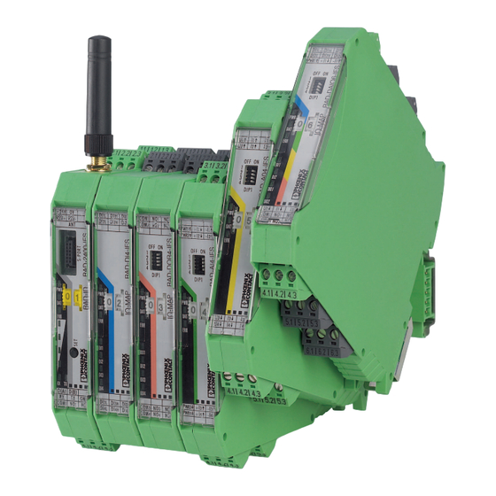
Radioline - wireless transmission system for serial interfaces and i/o signals
Hide thumbs
Also See for RAD-2400-IFS:
- User manual (213 pages) ,
- Quick start manual (2 pages) ,
- User manual (194 pages)

Related Manuals for Phoenix Contact RAD-2400-IFS


Summary of Contents for Phoenix Contact RAD-2400-IFS
- Page 1 Radioline - Wireless transmission system for serial interfaces and I/O signals User manual...
- Page 2 Radioline - Wireless transmission system for serial interfaces and I/O signals 2017-01-10 Designation: UM EN RAD-...-IFS Revision: This user manual is valid for: Wireless modules: Order No. RAD-2400-IFS 2901541 RAD-868-IFS 2904909 RAD-2400-IFS-JP 2702863 I/O extension modules: RAD-AI4-IFS 2901537 RAD-PT100-4-IFS 2904035...
-
Page 3: Rad-2400-Ifs
How to contact us Internet Up-to-date information on Phoenix Contact products and our Terms and Conditions can be found on the Internet at: phoenixcontact.com Make sure you always use the latest documentation. - Page 4 The receipt of technical documentation (in particular user documentation) does not constitute any further duty on the part of Phoenix Contact to furnish information on modifications to products and/or technical documentation. You are responsible to verify the suitability and intended use of the products in your specific application, in particular with regard to observing the applicable standards and regulations.
-
Page 5: Table Of Contents
Installation notes....................18 Installation in Zone 2.................... 19 Notes for individual I/O extension modules............21 UL notes (RAD-2400-IFS only) ................21 FCC and Industry Canada (RAD-2400-IFS only) ..........22 Short description ........................23 Wireless modules ....................23 Firmware versions ....................24 I/O extension modules.................. - Page 6 Free space path loss ..................141 9.11 Propagation of radio waves ................143 9.12 Fresnel zone...................... 146 9.13 Range........................ 148 9.14 Equivalent isotropically radiated power (EIRP) ..........149 9.15 System calculation in free space ............... 150 9.16 Practical examples .................... 151 PHOENIX CONTACT 105542_en_02...
- Page 7 Technical appendix.........................161 Typical combinations of antennas and adapter cables ........161 Control box for wireless systems ............... 175 PROFIBUS connections ..................176 Configuration ..................... 178 Appendixes..........................189 List of figures ..................... 189 List of tables ...................... 193 Index........................195 105542_en_02 PHOENIX CONTACT...
- Page 8 RAD-...-IFS PHOENIX CONTACT 105542_en_02...
-
Page 9: Technical Data For The Wireless Modules
Type Order No. Pcs./Pkt. 2400 MHz wireless transceiver with RS-232, RS-485 2-wire interface, can RAD-2400-IFS 2901541 be extended with I/O extension modules, with screw connection, antenna connection: RSMA (female), incl. DIN rail connector, without antenna 868 MHz wireless transceiver with RS-232, RS-485 2-wire interface, can... - Page 10 Pcs./Pkt. CONFSTICK for easy and safe network addressing for the 2.4 GHz Radio- RAD-CONF-RF3 2902814 line wireless module (RAD-2400-IFS), unique network ID, RF band 3 CONFSTICK for easy and safe network addressing for the 2.4 GHz Radio- RAD-CONF-RF5 2902815 line wireless module (RAD-2400-IFS), unique network ID, RF band 5 CONFSTICK for easy and safe network addressing for the 2.4 GHz Radio-...
- Page 11 FL LCX PIG-EF142-N-N 2700677 N (male) -> N (male), attenuation approximately 0.93 dB at 2.4 GHz and 1.6 dB at 5 GHz For RAD-2400-IFS: attachment plug with Lambda/4 technology as surge CN-LAMBDA/4-5.9-BB 2838490 protection for coaxial signal interfaces. Connection: N connectors...
- Page 12 Supply voltage range 19.2 V DC ... 30.5 V DC Maximum current consumption ≤65 mA (at 24 V DC, at 25°C, stand-alone) ≤6 A (at 24 V DC, with DIN rail connector at full capacity) Transient surge protection PHOENIX CONTACT 105542_en_02...
- Page 13 Technical data for the wireless modules System limits RAD-2400-IFS... RAD-868-IFS Wireless module Number of supported devices ≤250 (addressing via PSI-CONF soft- ≤99 (per wireless network) ware) ≤99 (addressing via thumbwheel) Number of possible extension modules ≤32 (per wireless module) ≤32 (per wireless module)
- Page 14 Vibration (operation) According to IEC 60068-2-6: 5g, 10 Hz ... 150 Hz Shock 16g, 11 ms Approvals RAD-2400-IFS RAD-868-IFS RAD-2400-IFS-JP CE conformity R&TTE Directive 1999/5/EC II 3 G Ex nA nC IIC T4 Gc (IBExU 15 ATEX B008 X) No...
- Page 15 Technical data for the wireless modules Conformity RAD-2400-IFS RAD-868-IFS Effective use of the radio spectrum according to EN 300328 EN 300220-2 Noise immunity according to EN 61000-6-2 Noise emission according to EN 61000-6-4 Electrical safety according to EN 60950-1 Operating conditions for the extended temperature range (+55°C ... 70°C) No function restrictions for the extended temperature range if you keep a minimum spacing of 17.5 mm be-...
-
Page 16: Rad-Ai4-Ifs
Maximum switching current: 1 A per channel RAD-AI4-IFS (2901537): Make sure that no more than 40 mA in total is drawn from loop power outputs ... PWR RAD-AO4-IFS (2901538): Only use the analog voltage output (0 V ... 10 V). PHOENIX CONTACT 105542_en_02... -
Page 17: For Your Safety
Operation of the wireless system is only permitted if accessories available from Phoenix Contact are used. The use of other accessory components could invalidate the op- erating license. You can find the approved accessories for this wireless system listed with the product at phoenixcontact.net/products. -
Page 18: Installation Notes
RAD-2400-IFS-JP wireless module The RAD-2400-IFS-JP wireless module is only approved for use in Japan. The RAD-2400-IFS-JP wireless module does not have ATEX approval. It is not suitable for use in potentially explosive areas. Only install the wireless module in the safe area. -
Page 19: Installation In Zone 2
WARNING: Explosion hazard when used in potentially explosive areas Make sure that the following notes and instructions are observed. The RAD-2400-IFS-JP wireless module does not have ATEX approval. It is not suitable for use in potentially explosive areas. Only install this wireless module in the safe area. - Page 20 The antennas are intended for use in potentially explosive areas that require 1G equipment. Connection is via antenna barriers (Order No. 2702198) with separate approval as intrinsically safe equipment. • Observe the safety notes in the documentation for the respective antenna. PHOENIX CONTACT 105542_en_02...
-
Page 21: Notes For Individual I/O Extension Modules
300 V. For RAD-AO4-IFS Use either the current or voltage output at every analog channel. UL notes (RAD-2400-IFS only) For RAD-2400-IFS wireless module INDUSTRIAL CONTROL EQUIPMENT FOR HAZARDOUS LOCATIONS 45FP This equipment is suitable for use in Class I, Zone 2, IIC T4 and Class I, Division 2, Groups A, B, C, D T4A hazardous locations or non-hazardous locations only. -
Page 22: Fcc And Industry Canada (Rad-2400-Ifs Only)
RAD-...-IFS FCC and Industry Canada (RAD-2400-IFS only) This device complies with Part 15 of the FCC rules. Operation is subject to the following two conditions: This device may not cause harmful interference. This device must accept any interference received, including interference that may cause undesired operation. -
Page 23: Short Description
Data rates and ranges can be configured using the PSI-CONF software – International approvals – Installation in Ex Zone 2 (RAD-2400-IFS and RAD-868-IFS only) – Can be combined with RS-485 stations The RAD-RS485-IFS RS-485 front module is not described in this user manual. For ad- ditional information, visit phoenixcontact.com/product/2702184. -
Page 24: Firmware Versions
Make sure that all the wireless modules in a network have the same firmware version. Where possible, always use the latest firmware. You can download the latest firmware free of charge at phoenixcontact.net/products. Table 3-1 Firmware versions Function As of firmware version ... RAD-2400-IFS RAD-868-IFS Initial version 1.00 1.00 PLC/Modbus RTU mode 1.30 1.00... -
Page 25: I/O Extension Modules
4 digital inputs RAD-DI4-IFS 2901535 8 digital inputs or 2 pulse RAD-DI8-IFS 2901539 inputs 4 digital relay outputs RAD-DOR4-IFS 2901536 8 digital transistor outputs RAD-DO8-IFS 2902811 Analog/ 1 analog input/output, RAD-DAIO6-IFS 2901533 digital 2 digital wide-range inputs/outputs 105542_en_02 PHOENIX CONTACT... - Page 26 RAD-...-IFS PHOENIX CONTACT 105542_en_02...
-
Page 27: Installation
Relay output with floating changeover contact (RF link relay) Status LED (RX/TX) for RS-232/RS-485 serial interface LED bar graph for displaying the wireless signal strength ERR status LED, red (communication error) DAT status LED, green (bus communication) PWR status LED, green (supply voltage) 105542_en_02 PHOENIX CONTACT... -
Page 28: Basic Circuit Diagram
2.4 GHz frequency band (e.g., WLAN, Bluetooth, microwave ovens). Otherwise, both the link quality and the data transmission speed will be re- duced. Figure 4-3 Radioline connection station with up to 32 I/O extension modules PHOENIX CONTACT 105542_en_02... - Page 29 Use a suitable screwdriver to release the locking mechanism on the snap-on foot of the device (see Figure 4-4, E). • Hold onto the device by the housing cover and carefully tilt it upwards. • Carefully lift the device off the DIN rail connector and the DIN rail. 105542_en_02 PHOENIX CONTACT...
-
Page 30: Connecting Cables
Fit the litz wires with ferrules. Permissible cable cross section: 0.2 mm ... 2.5 mm • Insert the wire with ferrule into the corresponding connection terminal block. • Use a screwdriver to tighten the screw in the opening above the connection terminal block. Tightening torque: 0.6 Nm. PHOENIX CONTACT 105542_en_02... -
Page 31: Connecting The Power Supply
Supply via system power supply – Parallel supply via the screw terminal blocks and with a system power supply via the bus foot is not possible. – For redundant supply, you can connect a second MINI-SYS-PS 100- 240AC/24DC/1.5 system power supply. 105542_en_02 PHOENIX CONTACT... -
Page 32: Serial Interfaces
If several devices are connected to a single bus, the shield must be connected to each device (e.g., by means of clamps). – Connect the bus shield to a central PE point using short, low-impedance connections with a large surface area (e.g., by means of shield connection clamps). PHOENIX CONTACT 105542_en_02... - Page 33 Connect the single wires of the data cable to the COMBICON plug-in screw terminal block (Figure 4-1, item 10). • Make sure the signal assignment is correct. COMBICON D(B) + (4.2) D(B) D(A) - (4.1) D(A) RS-485 Figure 4-9 RS-485 interface pin assignment 105542_en_02 PHOENIX CONTACT...
- Page 34 If you are not sure whether the device to be connected is of DTE or DCE type, you can also measure the voltage. Measure the voltage between Tx and GND in the idle state: – Voltage of approximately -5 V: DTE device – Voltage of approximately 0 V: DCE device PHOENIX CONTACT 105542_en_02...
-
Page 35: Connecting The Antenna
Please also observe the installation instructions for the antenna as well as Section “For your safety” on page 17. – For information on the transmission power, refer to “Transmission power” on page 46. S I+ S I- Figure 4-12 Connecting the antenna 105542_en_02 PHOENIX CONTACT... - Page 36 RAD-...-IFS PHOENIX CONTACT 105542_en_02...
-
Page 37: Configuration And Startup
All wireless modules are configured to the same default settings when delivered or following a reset at a later stage. Table 5-1 Default settings of the wireless module Parameter Setting RAD-2400-IFS RAD-2400-IFS-JP RAD-868-IFS Operating mode I/O data (wire in/wire out) Wireless interface... - Page 38 • Hold down the SET button until the DAT LED flashes. Reset via PSI-CONF software • In the device selection area, select “Wireless, RAD-2400-IFS” or “Wireless, RAD-868-IFS”. • Select “Local Device”. • Select “Set device to factory default configuration”.
-
Page 39: Operating Mode Of The Wireless Module
You can therefore establish a wireless connection to other wireless modules without any programming effort (see “Setting the address of the wireless module using the thumb- wheel” on page 42 and “Setting the address of the extension modules via the thumbwheel” on page 60). 105542_en_02 PHOENIX CONTACT... - Page 40 RX TX RX TX D(A) D(B) D(A) D(B) D(A) D(B) RS-485 RS-485 RS-485 Figure 5-2 I/O-to-I/O, wireless, and RS-485 The RAD-RS485-IFS RS-485 front module is not described in this user manual. For ad- ditional information, visit phoenixcontact.com/product/2702184. PHOENIX CONTACT 105542_en_02...
- Page 41 Modbus memory map of the master wireless module. In addition, the diagnostic data from all wireless devices is stored here. You need to configure each wireless module using the PSI-CONF software (from page 45 onwards). 105542_en_02 PHOENIX CONTACT...
-
Page 42: Setting The Address Of The Wireless Module Using The Thumbwheel
CONFSTICK from the wireless module. In addition, the CONFSTICK contains a preset frequency band (RF band). An RF band is a group of frequencies made up of individual frequencies from the entire frequency band. Dif- ferent RF bands use different frequencies. PHOENIX CONTACT 105542_en_02... - Page 43 Read-in has been completed when the DAT LED lights up once. The new pa- rameters are activated. • Remove the CONFSTICK from the wireless module. • Repeat this process for each individual wireless module in the network. 105542_en_02 PHOENIX CONTACT...
-
Page 44: Copying Device Settings Via A Memory Stick
Insert the memory stick in the S-PORT of the wireless module. The copying of param- eters is started automatically. • Wait until the running light stops. The write process has been completed. • Remove the memory stick from the wireless module. PHOENIX CONTACT 105542_en_02... -
Page 45: Configuration Via Psi-Conf Software
For additional information on the USB cable, please refer to the PACKB.RAD-CABLE- USB packing slip. The latest documentation can be downloaded via the product at phoenixcontact.net/product/2903447. • Install the software and the USB driver for the RAD-CABLE-USB cable. Follow the soft- ware wizard. 105542_en_02 PHOENIX CONTACT... - Page 46 Observe the maximum permissible radiated transmission power at the antenna (EIRP, see Table 5-4 or Table 5-5). If necessary, reduce the device transmission power via the PSI-CONF software. The transmission power can be calculated as follows: Device transmission power + Antenna gain - Cable attenuation PHOENIX CONTACT 105542_en_02...
- Page 47 Adherence to the Fresnel zone If you reduce the data transmission rate, obstacles such as walls or trees can be penetrated much better. Please note, however, that the delay time increases when the data rate is re- duced. 105542_en_02 PHOENIX CONTACT...
- Page 48 RAD-...-IFS Figure 5-7 PSI-CONF software: “Wizard, Step 3” Figure 5-8 PSI-CONF software: setting the data transmission rate PHOENIX CONTACT 105542_en_02...
- Page 49 5.6.4 Device settings By default upon delivery, the receive preamplifier is activated. The transmission power is set so that the devices can cover the greatest possible distances. – RAD-2400-IFS: 18 dBm – RAD-2400-IFS-JP: 20 dBm – RAD-868-IFS: 27 dBm Therefore, if the devices are operated directly next to one another the receiver may be- come overloaded.
- Page 50 Repeater chains are used to circumvent obstacles or to set up re- dundant wireless paths by means of several repeaters. The “Allowed Parents” tab is only available if the “Line/Mesh” network type has been se- lected. Figure 5-11 PSI-CONF software: “Individual Settings, Allowed Parents” PHOENIX CONTACT 105542_en_02...
-
Page 51: Diagnostics On The Wireless Module
Double assignment of I/O MAP address (e.g., two input mod- ules with the same I/O MAP address) – RAD ID changed – No Modbus communication Fast (2.8 Hz) Wireless connection interrupted Local bus error, e.g., input or output module not read 105542_en_02 PHOENIX CONTACT... - Page 52 In this case, remove the antennas, increase the distance between the devices and antennas or reduce transmission power using the PSI-CONF software (from page 45 onwards). PHOENIX CONTACT 105542_en_02...
- Page 53 LINK LED LINK LINK LINK LINK LINK ~1.0 V LED bar graph - running light The running light from bottom to top indicates: – Firmware update or – Wireless module in write mode for the memory stick 105542_en_02 PHOENIX CONTACT...
- Page 54 For example, the RSSI voltage may be helpful when positioning and aligning the antenna. The recommended minimum signal strength is 1.5 V DC. This results in a power reserve of around 10 dB, which ensures communication even in unfavorable transmission conditions. PHOENIX CONTACT 105542_en_02...
- Page 55 (par- ent). You can read the RSSI values via the serial interface of the master wireless module using Modbus/RTU commands (see Section “RSSI signal and error code registers” on page 86). 105542_en_02 PHOENIX CONTACT...
-
Page 56: Diagnostics Via Psi-Conf Software
Possible error messages: – Missing input module – Missing output module – Double assignment of I/O MAP address – Error on IFS bus – Wireless connection interrupted – RAD ID changed – CONFSTICK has not yet been inserted PHOENIX CONTACT 105542_en_02... - Page 57 The “I/O Status” tab displays the status and the current values of the connected I/O extension modules. Figure 5-16 PSI-CONF software: “Diagnostic, I/O Status” The “Serial Port” tab displays the parameters currently set for the RS-232/RS-485 interface. Figure 5-17 PSI-CONF software: “Diagnostic, Serial Port” 105542_en_02 PHOENIX CONTACT...
- Page 58 For I/O diagnostics: select the desired stations. • Select a storage location. Click on “Start Recording”. Diagnostic data is now written to a CSV file which can be opened with Excel, for example. Figure 5-19 PSI-CONF software: “Record diagnostic data, Network diagnostics” PHOENIX CONTACT 105542_en_02...
-
Page 59: Starting Up I/O Extension Modules
That is why only two modules in the network may have the same I/O MAP address. +24 V RSSI RSSI OFF ON DIP-1 RX TX D(A) D(B) +24 V RSSI RSSI OFF ON DIP-1 RX TX D(A) D(B) Figure 5-21 RAD-DAIO6-IFS assignment: analog/digital inputs and outputs 105542_en_02 PHOENIX CONTACT... - Page 60 Interface system slave address, for use with other Interface system master devices (IFS) The following conditions must be met: – Addresses 1 ... 99 (maximum) can be assigned for the extension modules in the entire wireless network. PHOENIX CONTACT 105542_en_02...
-
Page 61: Startup Time Of The Wireless Station
Each connected I/O extension module in- creases the startup time. Accordingly, a complete wireless station with 32 I/O extension modules may take several minutes to start up. Only after this time has elapsed is the wire- less station ready for operation. 105542_en_02 PHOENIX CONTACT... - Page 62 RAD-...-IFS PHOENIX CONTACT 105542_en_02...
-
Page 63: Serial Data Mode
When operating the network in serial data mode, it may not be possible to diagnose all devices. In this case, stop the serial application in order to perform full diagnostics. – Using the PSI-CONF software, you can assign different serial settings to the devices under “Individual Settings”. 105542_en_02 PHOENIX CONTACT... - Page 64 • Once you have performed all the steps in the wizard, you can save the project and transfer it to the wireless modules. Figure 6-2 PSI-CONF software: “Wizard, Step 3” Figure 6-3 PSI-CONF software: “Wizard, Step 4” PHOENIX CONTACT 105542_en_02...
-
Page 65: Frame-Based Data Transmission
IdleMin FrameEnd that is permitted between two characters in a frame. Otherwise the frame might be frag- mented. Frame 1 Frame 2 NOT OK Idle Idle Idle FrameEnd FrameEnd Figure 6-5 Frame-based data transmission: T parameter FrameEnd 105542_en_02 PHOENIX CONTACT... - Page 66 • To adapt data transmission to other protocols, you can adjust the T and T FrameEnd IdleMin parameters accordingly. Set the interface parameters under “Individual Settings”. Figure 6-6 PSI-CONF software: “Individual Settings” PHOENIX CONTACT 105542_en_02...
-
Page 67: Plc/Modbus Rtu Mode
I/O MAP addresses. Figure 7-1 PLC/Modbus RTU mode Configuration via PSI-CONF software • Start the PSI-CONF software (see page 45). • Create a new network project. • Follow the software wizard. Figure 7-2 PSI-CONF software: “Wizard, Step 3” 105542_en_02 PHOENIX CONTACT... -
Page 68: Addressing I/O Extension Modules
In PLC/Modbus RTU mode, a wireless network can have a maximum of 99 I/O extension modules. • Use the white thumbwheel on the I/O extension module to set the I/O MAP address. You can find information on addressing extension modules from page 60 onwards. PHOENIX CONTACT 105542_en_02... -
Page 69: Watchdog
If the watchdog is activated and Modbus communication interrupted, the red ERR LED will flash on all wireless modules in the network. Depending on the DIP switch settings, the out- put modules issue the corresponding hold or reset value. 105542_en_02 PHOENIX CONTACT... -
Page 70: Modbus Function Codes
3xxxx is already defined by the function code field. Function codes 03 and 16 You must enter 0031 (hex001F) as the start address in order to read or write registers 40032 ... 40039. The address range 4xxxx is already defined by the function code field. PHOENIX CONTACT 105542_en_02... -
Page 71: Module Type And Error Code Registers For I/O Extension Modules
“Currentness of data” register value is set to 1 until the output process data has been written to the Modbus registers. The read I/O data is only valid and current if a valid module type value is returned by the slave and the “Currentness of data” register value is 0. 105542_en_02 PHOENIX CONTACT... -
Page 72: Modbus Memory Map
LED 2 -100 dBm -95 dBm -90 dBm -85 dBm -80 dBm ≥2.0 V LED 1 -110 dBm -105 dBm -100 dBm -95 dBm -90 dBm ≥1.5 V LINK LED LINK LINK LINK LINK LINK ~1.0 V PHOENIX CONTACT 105542_en_02... - Page 73 If the module type in the register is invalid or unavailable, then the register value is 0. 30xx1 Reserved 30xx2 Analog input 1 (terminal point 2.x) 30xx3 Analog input 2 (terminal point 3.x) 30xx4 Analog input 3 (terminal point 4.x) 30xx5 Analog input 4 (terminal point 5.x) 30xx6 ... 30xx9 Reserved 105542_en_02 PHOENIX CONTACT...
- Page 74 Reserved 30xx2 Pt 100 input 1 (terminal point 2.x) 30xx3 Pt 100 input 2 (terminal point 3.x) 30xx4 Pt 100 input 3 (terminal point 4.x) 30xx5 Pt 100 input 4 (terminal point 5.x) 30xx6 ... 30xx9 Reserved PHOENIX CONTACT 105542_en_02...
- Page 75 If the module type in the register is invalid or unavailable, then the register value is 0. 40xx1 Reserved 40xx2 Analog output 1 (terminal point 2.x) 40xx3 Analog output 2 (terminal point 3.x) 40xx4 Analog output 3 (terminal point 4.x) 40xx5 Analog output 4 (terminal point 5.x) 40xx6 ... 40xx9 Reserved 105542_en_02 PHOENIX CONTACT...
- Page 76 In this case, the input process data is retained in the Modbus table, but is no longer updated. If the module type in the register is invalid or unavailable, then the register value is 0. 30xx1 Digital inputs DI4 DI3 DI2 DI1 Terminal point 30xx2 ... 30xx9 Reserved PHOENIX CONTACT 105542_en_02...
- Page 77 In this case, the input process data is retained in the Modbus table, but is no longer updated. If the module type in the register is invalid or unavailable, then the register value is 0. 105542_en_02 PHOENIX CONTACT...
- Page 78 Counter state DI7, high word 30xx6 ... 30xx9 Reserved 40xx1 Reset counter states DI1/DI7 Bit 1 = 1: counter state DI7 reset to 0 Bit 0 = 1: counter state DI1 reset to 0 40xx2 ... 40xx9 Reserved PHOENIX CONTACT 105542_en_02...
- Page 79 0 for the entire operating time of the device. If the module type in the register is invalid or unavailable, then the register value is 0. 40xx1 Digital outputs Terminal point 40xx2 ... 40xx9 Reserved 105542_en_02 PHOENIX CONTACT...
- Page 80 Short-circuit detection at the digital outputs Reserved Bit 1 = 1: short circuit detected at one output or several outputs 5 ... 8. Bit 0 = 1: short circuit detected at one output or several outputs 1 ... 4. PHOENIX CONTACT 105542_en_02...
- Page 81 The input process data is re- tained in the Modbus table, but is no longer updated. If the module type in the register is invalid or unavailable, then the register value is 0. 105542_en_02 PHOENIX CONTACT...
- Page 82 RAD-..-IFS 30xx1 Digital inputs DI2 DI1 Terminal point 30xx2 Analog input (terminal point 3.x) 30xx3 ... 30xx9 Reserved 40xx1 Digital outputs Terminal point 40xx2 Analog output (terminal point 4.x) Terminal point 40xx3 ... 40xx9 Reserved PHOENIX CONTACT 105542_en_02...
- Page 83 X X X X X X X X X X X X X X X X Counter state DI7 (high word) 30 xx 5 X X X X X X X X X X X X X X X X 30xx6 ... 30xx9 reserved 105542_en_02 PHOENIX CONTACT...
- Page 84 X X X X X X X X X X X X X X X X X X X X X X X X X X X X X X X X 30xx6 ... 30xx9 reserved 40xx6 ... 40xx9 reserved PHOENIX CONTACT 105542_en_02...
- Page 85 Example for reading temperature T1 (I/O MAP = 02): function code 04, start address 21 (hex15) ......30 99 0 40 99 0 105542_en_02 PHOENIX CONTACT...
- Page 86 The value 255 means that the RSSI value is invalid or the device cannot be reached. Example for reading the RSSI register of the station with RAD ID = 2: Function code 04, start address 5001 (hex1389) PHOENIX CONTACT 105542_en_02...
-
Page 87: Error Codes And Formats For Analog Input And Output Values
1770 6000 4 mA 4 mA 7530 30000 20 mA 20 mA 10 V 7F00 32512 21.67 mA 21.67 mA 10.84 V 8001 Overrange >21.67 mA >21.67 mA 8002 Open circuit <3.2 mA 8080 Underrange <0 mA 105542_en_02 PHOENIX CONTACT... - Page 88 Possible cause 0000 -50°C 0 mA 7530 30000 +250°C 20 mA 10 V 7F00 32512 +275.12°C 21.67 mA 10.84 V 8001 Overrange 8002 Open circuit Sensor wired incorrectly, measuring cable too long, cable resistance too high 8080 Underrange PHOENIX CONTACT 105542_en_02...
-
Page 89: Description Of I/O Extension Modules
Analog input 3 for 2, 3, 4-wire measuring transducers 5.1/5.2/5.3 Analog input 4 for 2, 3, 4-wire measuring transducers ERR status LED, red (communication error) DAT status LED, green (bus communication) PWR status LED, green (supply voltage) 105542_en_02 PHOENIX CONTACT... - Page 90 4 mA ... 20 mA 0 mA ... 20 mA Analog IN2 4 mA ... 20 mA 0 mA ... 20 mA Analog IN3 4 mA ... 20 mA 0 mA ... 20 mA Analog IN4 4 mA ... 20 mA PHOENIX CONTACT 105542_en_02...
- Page 91 Flashing Configuration and addressing mode Cyclic data communication ERR LED The red ERR LED indicates the error status. No error Flashing Slow (1.4 Hz) I/O MAP address changed Fast (2.8 Hz) No bus communication Critical internal error 105542_en_02 PHOENIX CONTACT...
- Page 92 The process image of the I/O extension module consists of six data words. For additional information, please refer to Section “RAD-AI4-IFS process data” on page 73. I/O module Module type ID Register Address range Function code RAD-AI4-IFS 30xx0 ... 30xx5 fc 04 PHOENIX CONTACT 105542_en_02...
-
Page 93: Rad-Pt100-4-Ifs - Extension Module With Four Temperature Inputs
At a temperature of 250°C at the Pt 100 input, a current of 20 mA or a voltage of 10 V is issued at the output. Table 8-3 Pt 100 input Pt 100 input Analog output -50°C 0 mA or 0 V +250°C 20 mA or 10 V 105542_en_02 PHOENIX CONTACT... - Page 94 +I and -I must have the same value. This allows you to subtract the established cable resistance from the measurement result and to get the Pt 100 platinum resistance value. IO-MAP ϑ U– I– µC Figure 8-6 3-wire connection technology PHOENIX CONTACT 105542_en_02...
- Page 95 Temperature measuring error for A = 0.5 mm Temperature measuring error for A = 1.0 mm Temperature measuring error for A = 1.5 mm (Measuring error valid for: copper cable χ = 57 m/Ωmm = 25°C, and Pt 100 sensor) 105542_en_02 PHOENIX CONTACT...
- Page 96 Since there are two cable resistances in the measuring system, the value must be doubled. Using the average temperature coefficient α = 0.385 Ω/K for Pt 100, the absolute measur- ing error in Kelvin can be determined for platinum sensors according to DIN. PHOENIX CONTACT 105542_en_02...
- Page 97 Pt 100 input 3 for 2 and 3-wire sensors 5.1/5.2/5.3 Pt 100 input 4 for 2 and 3-wire sensors ERR status LED, red (communication error) DAT status LED, green (bus communication) PWR status LED, green (supply voltage) 105542_en_02 PHOENIX CONTACT...
- Page 98 Basic circuit diagram for the RAD-PT100-4-IFS For 2-wire connection technology, an insertion bridge is required between terminal blocks x.2 and x.3. In this case, the measuring accuracy is reduced (see “Measuring errors when using 2-wire connection technology” on page 95). PHOENIX CONTACT 105542_en_02...
- Page 99 Flashing Configuration and addressing mode Cyclic data communication ERR LED The red ERR LED indicates the error status. No error Flashing Slow (1.4 Hz) I/O MAP address changed Fast (2.8 Hz) No bus communication Critical internal error 105542_en_02 PHOENIX CONTACT...
-
Page 100: Rad-Ao4-Ifs - Analog Extension Module With Four Outputs
The RAD-AO4-IFS analog I/O extension module can output up to four input signals with 0/4 mA ... 20 mA. All outputs are electrically isolated from one another, from the supply volt- age, and from the electronics. Use either the current or voltage output at every analog channel. PHOENIX CONTACT 105542_en_02... - Page 101 Analog output 4 (either current or voltage) ERR status LED, red (communication error) DAT status LED, green (bus communication) PWR status LED, green (supply voltage) 8.3.2 Basic circuit diagram IO-MAP 0/4...20 mA 0...10V DC µC Figure 8-15 Basic circuit diagram for the RAD-AO4-IFS 105542_en_02 PHOENIX CONTACT...
- Page 102 OFF ON DIP-1 Figure 8-16 DIP switches of the RAD-AO4-IFS Table 8-5 DIP switches of the RAD-AO4-IFS DIP switches Input Output signal RESET Analog OUT1 HOLD RESET Analog OUT2 HOLD RESET Analog OUT3 HOLD RESET Analog OUT4 HOLD PHOENIX CONTACT 105542_en_02...
- Page 103 Fast (2.8 Hz) Wireless module in I/O data mode – Missing input module – No bus communication Wireless module in PLC/Modbus RTU mode – No Modbus communication (safe state of outputs, depending on DIP switch settings) Critical internal error 105542_en_02 PHOENIX CONTACT...
-
Page 104: Rad-Di4-Ifs - Digital Extension Module With Four Inputs
0 V ... 50 V AC/DC at the low voltage input – 0 V ... 250 V AC/DC at the high voltage input All inputs are electrically isolated from one another, from the supply voltage, and from the electronics. PHOENIX CONTACT 105542_en_02... - Page 105 Status LEDs for digital inputs DI1 ... DI4 ERR status LED, red (communication error) DAT status LED, green (bus communication) PWR status LED, green (supply voltage) 8.4.2 Basic circuit diagram IO-MAP 10...50V AC/DC µC 50...250V AC/DC Figure 8-19 Basic circuit diagram for the RAD-DI4-IFS 105542_en_02 PHOENIX CONTACT...
- Page 106 No error Flashing Slow (1.4 Hz) I/O MAP address changed Fast (2.8 Hz) No bus communication Critical internal error DI1 ... DI4 The yellow DI1 ... DI4 LEDs indicate the state of the digital inputs. PHOENIX CONTACT 105542_en_02...
- Page 107 The process image of the I/O extension module consists of two data words. For additional information, please refer to Section “RAD-DI4-IFS process data” on page 76. I/O module Module type ID Register Address range Function code RAD-DI4-IFS 30xx0 ... 30xx1 fc 04 105542_en_02 PHOENIX CONTACT...
-
Page 108: Rad-Di8-Ifs - Digital Extension Module With Eight Inputs
Digital inputs 7 + 8, DI7: pulse input 2 Status LEDs for digital inputs DI1 ... DI8 CNT status LED, green (pulse counter mode) ERR status LED, red (communication error) DAT status LED, green (bus communication) PWR status LED, green (supply voltage) PHOENIX CONTACT 105542_en_02... - Page 109 In pulse counter mode, pulse inputs DI1 and DI7 are activated, 0 Hz ... 100 Hz pulses The pulse counter function is only available in PLC/Modbus RTU mode. Set the operating mode using the PSI-CONF software (from page 45 onwards). Figure 8-23 DIP switches of the RAD-DI8-IFS 105542_en_02 PHOENIX CONTACT...
- Page 110 DI7: bit 1 = 1 (register 40xx1) By setting the inputs • Set the corresponding input for at least 0.5 seconds: – Set input DI3 in order to reset counter state DI1. – Set input DI5 in order to reset counter state DI7. PHOENIX CONTACT 105542_en_02...
- Page 111 The red ERR LED indicates the error status. No error Flashing Slow (1.4 Hz) I/O MAP address changed or mode switched using DIP switch 1, but not yet applied Fast (2.8 Hz) No bus communication Critical internal error 105542_en_02 PHOENIX CONTACT...
- Page 112 Register Address range Function code 30xx0 ... 30xx1 fc 04 Static mode Static inputs 30xx0 ... 30xx5 fc 04 Pulse counter Pulse inputs RAD-DI8-IFS mode 40xx0 ... 40xx1 fc 03, 16 Pulse counter Reset counter mode states PHOENIX CONTACT 105542_en_02...
-
Page 113: Rad-Dor4-Ifs - Digital Extension Module With Four Outputs
Relay output 3 with floating PDT contact 6.1/6.2/6.3 Relay output 4 with floating changeover contact Status LEDs for relay outputs DO1 ... DO4 ERR status LED, red (communication error) DAT status LED, green (bus communication) PWR status LED, green (supply voltage) 105542_en_02 PHOENIX CONTACT... -
Page 114: Figure 8-26 Basic Circuit Diagram For The Rad-Dor4-Ifs
Any changes to the DIP switch set- tings will be applied immediately. – RESET = output value is set to 0 – HOLD = hold the last output value OFF ON DIP-1 Figure 8-27 DIP switches of the RAD-DOR4-IFS PHOENIX CONTACT 105542_en_02... -
Page 115: Figure 8-28: Diagnostic Leds Of The Rad-Dor4-Ifs
The green PWR LED indicates the status of the supply voltage. No supply voltage Supply voltage OK DAT LED The green DAT LED indicates the status of bus communication. No communication Flashing Configuration and addressing mode Cyclic data communication 105542_en_02 PHOENIX CONTACT... - Page 116 The process image of the I/O extension module consists of two data words. For additional information on the process data, please refer to Section “RAD-DOR4-IFS process data” on page 79. I/O module Module type ID Register Address range Function code RAD-DOR4-IFS 10 40xx0 ... 40xx1 fc 03, 16 PHOENIX CONTACT 105542_en_02...
-
Page 117: Rad-Do8-Ifs - Digital Extension Module With Eight Outputs
Terminal block 1.1 (12 V DC ... 30.5 V DC) – Terminal blocks 1.2/1.3 (GND) • Outputs DO5 ... DO8 are supplied via: – Terminal block 6.1 (12 V DC ... 30.5 V DC) – Terminal blocks 6.2/6.3 (GND) 105542_en_02 PHOENIX CONTACT... -
Page 118: Figure 8-29 Rad-Do8-Ifs Structure
Transistor outputs 7 + 8 6.1/6.2/6.3 Supply voltage for outputs 5 ... 8 Status LEDs of transistor outputs DO1 ... DO8 ERR status LED, red (communication error) DAT status LED, green (bus communication) PWR status LED, green (supply voltage) PHOENIX CONTACT 105542_en_02... -
Page 119: Figure 8-30 Basic Circuit Diagram For The Rad-Do8-Ifs
Any changes to the DIP switch set- tings will be applied immediately. – RESET = output value is set to 0 – HOLD = hold the last output value Figure 8-31 DIP switches of the RAD-DO8-IFS 105542_en_02 PHOENIX CONTACT... -
Page 120: Figure 8-32 Diagnostics Leds Of The Rad-Do8-Ifs
The green PWR LED indicates the status of the supply voltage. No supply voltage Supply voltage OK DAT LED The green DAT LED indicates the status of bus communication. No communication Flashing Configuration and addressing mode Cyclic data communication PHOENIX CONTACT 105542_en_02... - Page 121 Setting the I/O MAP address for the RAD-DO8-IFS Thumbwheel Description 01 ... 99 I/O MAP address Delivery state **, 1* ... 9* Setting not permitted *1 ... *9 Interface system slave address, for use with other Interface system (IFS) master devices 105542_en_02 PHOENIX CONTACT...
-
Page 122: Rad-Daio6-Ifs - Analog/Digital Extension Module With Six Channels
The analog output is designed as an active output. You can select a current signal of 0/4 mA ... 20 mA or a voltage signal of 0 V ... 10 V. Use either a current or voltage output at the analog output. PHOENIX CONTACT 105542_en_02... -
Page 123: Figure 8-33 Rad-Daio6-Ifs Structure
Relay output with floating changeover contact Status LEDs of digital outputs DO1 ... DO2 Status LEDs of digital inputs DI1 ... DI2 ERR status LED, red (communication error) DAT status LED, green (bus communication) PWR status LED, green (supply voltage) 105542_en_02 PHOENIX CONTACT... -
Page 124: Figure 8-34 Basic Circuit Diagram For The Rad-Daio6-Ifs
RESET = output value is set to 0 – HOLD = hold the last output value Digital outputs – RESET = relay drops out – HOLD = hold the last valid state Figure 8-35 DIP switches of the RAD-DAIO6-IFS PHOENIX CONTACT 105542_en_02... -
Page 125: Figure 8-36 Diagnostic Leds Of The Rad-Daio6-Ifs
The green PWR LED indicates the status of the supply voltage. No supply voltage Supply voltage OK DAT LED The green DAT LED indicates the status of bus communication. No communication Flashing Configuration and addressing mode Cyclic data communication 105542_en_02 PHOENIX CONTACT... - Page 126 The process image of the I/O extension module consists of six data words. For additional information, please refer to Section “RAD-DAIO6-IFS process data” on page 81. I/O module Module type ID Register Address range Function code (inputs) 30xx0 ... 30xx2 fc 04 RAD-DAIO6-IFS 60 40xx0 ... 40xx2 fc 03, 16 (outputs) PHOENIX CONTACT 105542_en_02...
-
Page 127: Planning Wireless Systems
The larger the network, the higher the delay time. – Distance and set data rate of the wireless interface The lower the data rate via the wireless interface, the higher the delay time. – Data encryption If data encryption is activated, the delay time increases. 105542_en_02 PHOENIX CONTACT... - Page 128 2.8 s I/O data mode: the telegram length depends on the number of I/O extension modules. Serial data mode: the telegram length depends on the protocol used and the terminal devices that are connected to the serial interface. PHOENIX CONTACT 105542_en_02...
-
Page 129: Pulse Transmission
The Modbus register can be read and written by any PLC via Modbus/RTU. Trusted Wireless 2.0 Phoenix Contact has developed Trusted Wireless 2.0 technology specifically for industrial applications. Trusted Wireless 2.0 operates in the license-free 2.4 GHz or 868 MHz fre- quency bands. - Page 130 The relationship between range and data rate can be illustrated by the energy per bit trans- mitted. The higher the energy per bit, the greater the achievable range. The energy per bit results from the ratio between transmission power and data rate: energy per bit = transmission power/data rate PHOENIX CONTACT 105542_en_02...
-
Page 131: Figure 9-1 Penetration Of Obstacles At Different Frequencies
868 MHz band. In the 869.4 MHz ... 869.65 MHz fre- quency band, the maximum transmission time is 10% of one hour (6 minutes). The duty cycle is not usually reached during operation, since only low volumes of data (I/O signals or serial data) are transmitted. 105542_en_02 PHOENIX CONTACT... -
Page 132: Figure 9-2: Point-To-Point Connection, Star Network, Self-Healing Mesh Network
This reduces the message traffic volume and speeds up data exchange. Parent-Child-Zone 1 Parent-Child-Zone 2.1 Parent-Child-Zone 2.2 M = Master R = Repeater S = Slave Parent-Child-Zone 3.1 Figure 9-3 Distributed network management with parent-child zones PHOENIX CONTACT 105542_en_02... -
Page 133: Rf Bands
1.2 kbps 60 kbps 19.2 kbps 9.6 kbps 120 kbps 1 RF band (fixed frequency) 14 RF bands (fixed frequency) 2 RF bands (frequency hopping spread spectrum method) Figure 9-5 RF bands in the 868 MHz wireless system 105542_en_02 PHOENIX CONTACT... -
Page 134: Planning Wireless Paths
Of course, a connection path without any obstacles would be perfect. However, small obstacles in the Fresnel zone will not necessarily disturb com- munication. In general, obstacles in the way on long wireless paths have a greater influence than those on short ones. PHOENIX CONTACT 105542_en_02... -
Page 135: Selecting Antenna Cables And Antennas
In reflective environments the signal can be received via an indirect route. Directional antenna – Large distances – Point-to-point connections – Stationary or linear mobile applications – Multiple point-to-point paths, decoupling due to directivity and different polarization levels (see Figure 9-7) 105542_en_02 PHOENIX CONTACT... -
Page 136: Installing Antennas
The partner antennas must therefore be polarized vertically. Vertical polarization means that the elements are aligned vertically to the horizon. Crossing polarization between the stations results in signal loss (see Table 9-4). Figure 9-6 Antenna polarization PHOENIX CONTACT 105542_en_02... -
Page 137: Figure 9-7: Decoupling Wireless Paths Due To Directivity And Different Polarization Levels
If you operate several wireless paths directly next to one another in parallel, you can al- ternately align directional antennas horizontally and vertically. The signals of the vari- ous wireless paths will therefore be decoupled. Figure 9-7 Decoupling wireless paths due to directivity and different polarization levels 105542_en_02 PHOENIX CONTACT... -
Page 138: Figure 9-8 Outdoor Installation Of Antennas
Thanks to excellent impedance matching, the surge protection does not distort the useful signal. • Use surge protection for installation outdoors. – For RAD-2400-IFS...: CN-LAMBDA/4-5.9-BB, Order No. 2838490 – For RAD-868-IFS: CN-LAMBDA/4-2.2-BB, Order No. 2800024 • The antenna is grounded via the surge protection. -
Page 139: Level And Attenuation Of Wireless Modules And Accessories
The total cable attenuation including connectors is specified in the table. Table 9-5 Levels and attenuation of the wireless devices and accessories Trusted Wireless module Order No. Max. transmission Connection Wireless power RAD-2400-IFS 2901541 2.4 GHz 20 dBm RAD-2400-IFS-JP 2702863 RSMA (f) 868 MHz RAD-868-IFS 2904909... - Page 140 N(f) 2904802 2 dBi 2.4 GHz directional antenna ANT-DIR-2459-01 N(f) 2701186 9 dBi RAD-ISM-2400-ANT-PAR-19-0 N(f) 2867885 19 dBi 868 MHz directional antenna ANT-DIR-868-01 N(f) 2702137 3.5 dBi RAD-ISM-900-ANT-YAGI-6.5-N N(f) 2867814 8.5 dBi RAD-ISM-900-ANT-YAGI-10-N N(f) 5606614 12 dBi PHOENIX CONTACT 105542_en_02...
-
Page 141: Free Space Path Loss
950 m -99.6 dB 1000 m -100 dB -91.2 dB 2000 m -97.2 dB 3000 m -100.7 dB 4000 m -103.2 dB 5000 m -105.1 dB 6000 m -106.7 dB 7000 m -108.1 dB 8000 m -109.2 dB 105542_en_02 PHOENIX CONTACT... - Page 142 Formula for 868 MHz: free space path loss [dB] = 91.17 + 20 x log(d) f = transmission frequency in MHz d = distance between the antennas in km The free space path loss is later included in the system calculation (see Section “Equivalent isotropically radiated power (EIRP)” on page 149). PHOENIX CONTACT 105542_en_02...
-
Page 143: Propagation Of Radio Waves
Reflection on a smooth metal surface involves virtually the entire wireless signal being re- flected at the same angle. In certain applications, the reflection may have a positive effect, e.g., if there is no line of sight. Reflections mainly occur in buildings. Figure 9-11 Reflection on a metal surface 105542_en_02 PHOENIX CONTACT... -
Page 144: Figure 9-12 Reduction Of Radio Waves When Penetrating A Wall
11 ... 20 Forest, 1 m, see 9.16 “Practical 9 ... 14 4 ... 8 examples” Heat-absorbing glass with metal 40 ... 50 30 ... 40 coating Figure 9-12 Reduction of radio waves when penetrating a wall PHOENIX CONTACT 105542_en_02... -
Page 145: Figure 9-13 Angle Of The Transmitter And Receiver
+24 V 0 V RSSI+ RSSI- RX TX D(A) D(B) +24 V 0 V RSSI+ RSSI- RX TX D(A) D(B) Figure 9-14 Radio dead spot 105542_en_02 PHOENIX CONTACT... -
Page 146: Fresnel Zone
They contribute to a good wireless connection even if the Fresnel zone is not free from obstacles. The following figure shows the Fresnel zone between two antennas. The required mounting height for the antennas depends on the radius of the Fresnel zone. PHOENIX CONTACT 105542_en_02... -
Page 147: Figure 9-16 Fresnel Zone
Radius of the Fresnel zone for 2.4 GHz and d = 3000 m: r = 9.68 m Result: the radius of the Fresnel zone is 9.68 m at a wavelength of 0.125 m (2.4 GHz) and a distance of 3000 m between the antennas. 105542_en_02 PHOENIX CONTACT... -
Page 148: Range
Data rate of the Maximum range wireless interface Outside buildings, with a free line of sight 120 kbps 4 km 60 kbps 5 km Omnidirectional antenna, 4 dBi 19.2 kbps 8 km 9.6 kbps 9 km 1.2 kbps 11 km PHOENIX CONTACT 105542_en_02... -
Page 149: Equivalent Isotropically Radiated Power (Eirp)
Maximum of 19 dBm in Europe, depending on the set transmission rate – For 868 MHz: – Maximum of 27 dBm • If the maximum EIRP is exceeded, adapt the cable, adapter or transmission power if necessary. 105542_en_02 PHOENIX CONTACT... -
Page 150: System Calculation In Free Space
System reserve = |-96 dB| - |-67.7 dB| = 28.3 dB 28.3 dB > 10 dB Conclusion: The losses of -67.7 dB are significantly lower than the receiver sensitivity of -96 dB. The desired wireless connection is therefore possible in mathematical terms. PHOENIX CONTACT 105542_en_02... -
Page 151: Practical Examples
5 to 20 cm. In our test, the 2.4 GHz wireless signal was transmitted through a 25 m forest. The attenuation was around 40 dB. For 868 MHz, the attenuation is around 22 dB. Figure 9-19 Forest with an attenuation of around 40 dB 105542_en_02 PHOENIX CONTACT... - Page 152 RAD-...-IFS PHOENIX CONTACT 105542_en_02...
-
Page 153: 10 Detecting And Removing Errors
At a slave or repeater, it is only possible to read the RSSI voltage of the connected wireless module. For more information on the RSSI voltage, please refer to Table 5-7 and Table 5-8. 105542_en_02 PHOENIX CONTACT... - Page 154 The data of the I/O extension modules is read in again. connector and the bus. ERR, DAT Writing to the memory stick did • Repeat the process in order to correctly write to the memory stick. flashing not work. PHOENIX CONTACT 105542_en_02...
- Page 155 1 m in the horizontal direction or 0.6 m in the vertical direction). • Make sure that the power supply is sufficient. • Make sure that there is no connection between the core and the shield of the cable in the connected antenna system. 105542_en_02 PHOENIX CONTACT...
- Page 156 Example: the yellow thumb- • If necessary, set the correct RAD ID and press the SET button. wheel setting has accidentally been modified and the modifica- tion has not yet been confirmed via the SET button. PHOENIX CONTACT 105542_en_02...
- Page 157 Check the wiring of the RS-232/RS-485 connections on the wireless but application does not trans- modules. mit any data. • Check the serial interface settings (baud rate, parity, data bits, and stop bits) for the wireless modules and serial terminal devices (from page 45 onwards). 105542_en_02 PHOENIX CONTACT...
- Page 158 • Reset the wireless module to the default settings (I/O data mode, see page 37), if necessary. Critical internal error • Please contact Phoenix Contact technical support. ERR ON Example: technical defect I/O MAP address changed • Check the I/O MAP address setting on the white thumbwheel of the I/O extension module.
-
Page 159: Loopback Test During Serial Data Transmission
If the characters only appear once, check the HyperTerminal settings for hidden outgoing characters. The following options must be enabled under “File, Proper- ties, Settings, ASCII Setup”: “Echo typed characters locally” and “Append line feeds to incoming line ends” 105542_en_02 PHOENIX CONTACT... -
Page 160: Figure 10-2 Settings In Hyperterminal
RAD-...-IFS Figure 10-2 Settings in HyperTerminal PHOENIX CONTACT 105542_en_02... -
Page 161: A Technical Appendix
Omnidirectional antenna, 2 dBi Item Product Description Connection Order No. RAD-ISM-2400-ANT-OMNI-2-1- Omnidirectional antenna, 2.4 GHz, 2 dBi gain, RSMA (male) 2701362 RSMA 1.5 m cable length, linear vertical polarization, h/v 360°/75° opening angle, IP65 degree of protection 105542_en_02 PHOENIX CONTACT... -
Page 162: Figure A-2: Omnidirectional Antenna With Protection Against Vandalism, 3 Dbi
Order No. RAD-ISM-2400-ANT-VAN-3-0- Omnidirectional antenna with protection RSMA (male) 2701358 RSMA against vandalism, 2.4 GHz, 3 dBi gain, IP55 degree of protection, 1.5 m cable length, h/v 360°/85° opening angle Appropriate mounting material is available for wall mounting. PHOENIX CONTACT 105542_en_02... -
Page 163: Figure A-3: Omnidirectional Antenna, 2.5 Dbi
N (male) 2701408 2.5/5 dBi gain, linear vertical polarization, opening angle: h/v 360°/30° for 2.4 GHz, h/v 360°/16° for 5 GHz, IP68 N (female) RAD-PIG-EF316-N-RSMA Adapter cable, 50 cm pigtail, 50 Ω impedance 2701402 RSMA (male) 105542_en_02 PHOENIX CONTACT... -
Page 164: Figure A-4: Omnidirectional Antenna, 6 Dbi, Without Surge Protection
2903263 RSMA (male) Alternative: RAD-PIG-RSMA/N-1 Antenna cable, 1 m length 2903264 RAD-PIG-RSMA/N-2 Antenna cable, 2 m length N (male) 2903265 RSMA (male) RAD-PIG-RSMA/N-3 Antenna cable, 3 m length 2903266 RAD-PIG-RSMA/N-5 Antenna cable, 5 m length 2702140 PHOENIX CONTACT 105542_en_02... -
Page 165: Figure A-5: Omnidirectional Antenna, 6 Dbi, With Surge Protection
N (male) RAD-CAB-EF393-10M Antenna cable, 10 m length 2867665 N (male) RAD-CAB-EF393-15M Antenna cable, 15 m length 2885634 N (female) CN-LAMBDA/4-5.9-BB Attachment plug with Lambda/4 technology as 2838490 surge protection for coaxial signal interfaces N (female (opt.) 105542_en_02 PHOENIX CONTACT... - Page 166 2903263 RSMA (male) Alternative: RAD-PIG-RSMA/N-1 Antenna cable, 1 m length 2903264 RAD-PIG-RSMA/N-2 Antenna cable, 2 m length N (male) 2903265 RSMA (male) RAD-PIG-RSMA/N-3 Antenna cable, 3 m length 2903266 RAD-PIG-RSMA/N-5 Antenna cable, 5 m length 2702140 PHOENIX CONTACT 105542_en_02...
-
Page 167: Figure A-6: Directional Antenna, 9 Dbi, With Outdoor Surge Protection
2903263 RSMA (male) Alternative: RAD-PIG-RSMA/N-1 Antenna cable, 1 m length 2903264 RAD-PIG-RSMA/N-2 Antenna cable, 2 m length N (male) 2903265 RSMA (male) RAD-PIG-RSMA/N-3 Antenna cable, 3 m length 2903266 RAD-PIG-RSMA/N-5 Antenna cable, 5 m length 2702140 105542_en_02 PHOENIX CONTACT... -
Page 168: Figure A-7: Parabolic Antenna, 19 Dbi, With Outdoor Surge Protection
2903263 RSMA (male) Alternative: RAD-PIG-RSMA/N-1 Antenna cable, 1 m length 2903264 RAD-PIG-RSMA/N-2 Antenna cable, 2 m length N (male) 2903265 RSMA (male) RAD-PIG-RSMA/N-3 Antenna cable, 3 m length 2903266 RAD-PIG-RSMA/N-5 Antenna cable, 5 m length 2702140 PHOENIX CONTACT 105542_en_02... -
Page 169: Figure A-8: Omnidirectional Antenna, 4 Dbi, With Surge Protection
N (male) RAD-CAB-EF393-10M Antenna cable, 10 m length 2867665 N (male) RAD-CAB-EF393-15M Antenna cable, 15 m length 2885634 N (female) CN-LAMBDA/4-2.2-BB Attachment plug with Lambda/4 technology as 2800024 surge protection for coaxial signal interfaces N (female (opt.) 105542_en_02 PHOENIX CONTACT... -
Page 170: Figure A-9: Directional Antenna, With Surge Protection
25 mm ... 85 mm diameter, stainless steel, ATEX/IECEx approval Alternative: RAD-ISM-900-ANT-YAGI-6.5-N Yagi antenna, IP65, 8.5 dBi gain, 0.6 m cable 2867814 length N (female) RAD-ISM-900-ANT-YAGI-10-N Yagi antenna, IP65, 12.15 dBi gain, 0.6 m 5606614 RG-213 cable PHOENIX CONTACT 105542_en_02... - Page 171 2903263 RSMA (male) Alternative: RAD-PIG-RSMA/N-1 Antenna cable, 1 m length 2903264 RAD-PIG-RSMA/N-2 Antenna cable, 2 m length N (male) 2903265 RSMA (male) RAD-PIG-RSMA/N-3 Antenna cable, 3 m length 2903266 RAD-PIG-RSMA/N-5 Antenna cable, 5 m length 2702140 105542_en_02 PHOENIX CONTACT...
-
Page 172: Figure A-10: Directional Antennas, 8 Dbi, With 2-Way Outdoor Antenna Splitter
IP67, incl. mounting bracket and mast clips for 25 mm ... 85 mm diameter, stain- less steel, ATEX/IECEx approval Or other directional antennas from Phoenix Contact FL LCX PIG-EF142-N-N Antenna cable, 50 cm length, 50 Ω impedance N (male) 2700677 ... -
Page 173: Figure A-11: Antenna Installation In Zone 2
17. 24V 13 OUT DC 24V 1.5A +24 V 24V 0V 0V RSSI RSSI OFF ON OFF ON OFF ON DIP-1 DIP-1 DIP-1 RX TX D(A) D(B) IN AC 100-240V Figure A-11 Antenna installation in Zone 2 105542_en_02 PHOENIX CONTACT... - Page 174 RAD-...-IFS Item Product Description Connection Order No. IP54 stainless steel housing Power supply RAD-2400-IFS or RAD-868-IFS wireless module and I/O extension modules Antenna cable, 0.5 m length, 50 Ω impedance N (male) RAD-PIG-RSMA/N-0.5 2903263 RSMA (male) Alternative: RAD-PIG-RSMA/N-1 Antenna cable, 1 m length 2903264 N (male) ...
-
Page 175: A 2 Control Box For Wireless Systems
Mounting example with a 35 mm power supply and five 17.5 mm devices and terminal blocks Power supply MINI-SYS-PS-100-240AC/24DC/1.5 1500 mA Load Wireless module 65 mA RAD-DAIO6-IFS 95 mA RAD-DI4-IFS 11 mA RAD-DOR4-IFS 55 mA RAD-DI8-IFS 18 mA RAD-DO8-IFS 22 mA RAD-AI4-IFS 120 mA RAD-AO4-IFS 115 mA 105542_en_02 PHOENIX CONTACT... -
Page 176: A 3 Profibus Connections
They are therefore not suitable for wireless connections. Point-to-point connection SIEMENS SIEMENS +24 V +24 V RSSI RSSI RSSI RSSI SIMATIC SIMATIC S7-300 S7-300 RX TX RX TX D(A) D(B) D(A) D(B) Figure A-13 Point-to-point connection with PROFIBUS PHOENIX CONTACT 105542_en_02... -
Page 177: Figure A-14 Star Structure With Profibus, Up To 10 Slaves
RX TX D(A) D(B) D(A) D(B) SIEMENS +24 V RSSI RSSI SIMATIC S7-300 RX TX D(A) D(B) SIEMENS +24 V RSSI RSSI SIMATIC S7-300 RX TX D(A) D(B) Figure A-14 Star structure with PROFIBUS, up to 10 slaves 105542_en_02 PHOENIX CONTACT... -
Page 178: A 4 Configuration
Install the software on your computer. WARNING: Explosion hazard when used in potentially explosive areas The USB cable must not be used in potentially explosive areas. • To connect the wireless module to the PC, use the RAD-CABLE-USB cable (Order No. 2903447). PHOENIX CONTACT 105542_en_02... -
Page 179: Figure A-16 Psi-Conf Software
Configuration • Start the PSI-CONF software. Figure A-16 PSI-CONF software • Select the device from the “Wireless” tab. Figure A-17 PSI-CONF software: “Device selection” 105542_en_02 PHOENIX CONTACT... -
Page 180: Figure A-18 Psi-Conf Software: "Network Project
RAD-...-IFS • Select “Create new network project”. Figure A-18 PSI-CONF software: “Network Project” • In step 1 of the wizard, select “Point to Point / Star”. Confirm with “Next”. Figure A-19 PSI-CONF software: “Wizard, Step 1” PHOENIX CONTACT 105542_en_02... -
Page 181: Figure A-20: Psi-Conf Software: "Wizard, Step 2
Depending on the distance between the wireless modules, you can set the desired data rate under “Network speed/distance relation”. For additional information on the relationship between speed and distance, please refer to Table 5-4. • Then confirm with “Next”. Figure A-21 PSI-CONF software: “Wizard, Step 3” 105542_en_02 PHOENIX CONTACT... -
Page 182: Figure A-22: Psi-Conf Software: "Wizard, Step 4
Figure A-22 PSI-CONF software: “Wizard, Step 4” • In step 5, you will see an overview of the settings that have already been made. Check these settings and confirm with “Next”. Figure A-23 PSI-CONF software: “Wizard, Step 5” PHOENIX CONTACT 105542_en_02... -
Page 183: Figure A-24: Psi-Conf Software: "Wizard, Step 6
PROFIBUS segment. To do this, set DIP switches 1 and 2 to ON. The DIP switch- es are located on the side of the wireless module. Configuring the PROFIBUS master • Adjust the timing in the PROFIBUS master to the signal runtime via the wireless path. 105542_en_02 PHOENIX CONTACT... - Page 184 1 analog value = 1 word = 2 bytes OTA125k@PB93.75k = 110 bytes = 55 analog values – 1 digital value = 1 bit = 8 values per byte OTA125k@PB93.75k = 110 bytes = 880 digital values PHOENIX CONTACT 105542_en_02...
-
Page 185: Figure A-26 Simatic ® Manager
Manager. Open your user project. Select “Options, Configure Net- work” from the pull-down menu. ® Figure A-26 SIMATIC Manager • In the “NetPro” window, right-click the PROFIBUS line. Then select “Object Properties” from the context menu. Figure A-27 “NetPro” window 105542_en_02 PHOENIX CONTACT... -
Page 186: Figure A-28 "Network Settings" Tab, Transmission Rate
In the “Cables” tab, deactivate the “Take into account the following cable configuration” check box. Confirm with “OK”. Figure A-29 “Cables” tab • In the “Network Settings” tab, select the “User-Defined” profile and the “Bus Parame- ters” option. Figure A-30 “Network Settings” tab, profile PHOENIX CONTACT 105542_en_02... -
Page 187: Figure A-31 "Bus Parameters" Tab
Calculating the bus parameters also modifies the response monitoring (watchdog) val- ue. Enter 93750 t_bit here to achieve a response monitoring (watchdog) time of 1 second for the PROFIBUS slave. Confirm with “OK”. Figure A-32 “Bus Parameters” tab, response monitoring 105542_en_02 PHOENIX CONTACT... -
Page 188: Figure A-33 "Properties - Dp" Tab
To ensure error-free operation, the “Test, commissioning, routing” check box must not be enabled. If this option is activated, the interface becomes an active PROFIBUS device and takes part in the token rotation of PROFIBUS. Figure A-33 “Properties - DP” tab PHOENIX CONTACT 105542_en_02... -
Page 189: Appendixes
PSI-CONF software: “Diagnostic, Network settings” ......58 Figure 5-19: PSI-CONF software: “Record diagnostic data, Network diagnostics” . 58 Figure 5-20: Assignment of digital inputs and digital outputs ........59 Figure 5-21: RAD-DAIO6-IFS assignment: analog/digital inputs and outputs ..59 105542_en_02 PHOENIX CONTACT... - Page 190 RAD-DI8-IFS structure ..............108 Figure 8-22: Basic circuit diagram for the RAD-DI8-IFS ........109 Figure 8-23: DIP switches of the RAD-DI8-IFS ............. 109 Figure 8-24: Diagnostic LEDs of the RAD-DI8-IFS ..........111 Figure 8-25: RAD-DOR4-IFS structure ..............113 PHOENIX CONTACT 105542_en_02...
- Page 191 Omnidirectional antenna with protection against vandalism, 3 dBi ... 162 Figure A-3: Omnidirectional antenna, 2.5 dBi ............163 Figure A-4: Omnidirectional antenna, 6 dBi, without surge protection ....164 Figure A-5: Omnidirectional antenna, 6 dBi, with surge protection ...... 165 105542_en_02 PHOENIX CONTACT...
- Page 192 Figure A-29: “Cables” tab ..................186 Figure A-30: “Network Settings” tab, profile ............186 Figure A-31: “Bus Parameters” tab ................ 187 Figure A-32: “Bus Parameters” tab, response monitoring ........187 Figure A-33: “Properties - DP” tab ................. 188 PHOENIX CONTACT 105542_en_02...
-
Page 193: B 2 List Of Tables
Representation of RAD-DAIO6-IFS analog values ......87 Table 7-20: Representation of the RAD-PT100-4-IFS Pt 100 values ...... 88 Table 8-1: DIP switches of the RAD-AI4-IFS............90 Table 8-2: Setting the I/O MAP address for the RAD-AI4-IFS....... 92 Table 8-3: Pt 100 input..................93 105542_en_02 PHOENIX CONTACT... - Page 194 Table 9-10: Ranges for different antennas at 868 MHz......... 148 Table 10-1: Detecting and removing errors: wireless module ....... 154 Table 10-2: Detecting and removing errors: I/O extension module ....... 158 Table A-1: Possible PROFIBUS telegram lengths..........184 PHOENIX CONTACT 105542_en_02...
-
Page 195: B 3 Index
Bus connector RAD-AO4-IFS ............. 103 See DIN rail connector RAD-DAIO6-IFS ..........125 RAD-DI4-IFS ............106 RAD-DI8-IFS ............111 Cable ..............135, 161 RAD-DO8-IFS ............. 120 Checking the location..........134 RAD-DOR4-IFS........... 115 RAD-PT100-4-IFS ..........99 Wireless module............ 51 105542_en_02 PHOENIX CONTACT... - Page 196 Multipath propagation ......... 54, 143 Pt 100 values............88 Multipathing Frame-based data transmission........64 See Multipath propagation Free space path loss......... 141, 150 Frequency hopping spread spectrum method... 130 Fresnel zone ............. 146 Function code ............. 70 Network key ..............42 PHOENIX CONTACT 105542_en_02...
- Page 197 To default settings ..........38 RAD-DI8-IFS ............77 Residential area ............17 RAD-DO8-IFS ............80 RF band ..............42 RAD-DOR4-IFS............. 79 RAD-2400-IFS............. 133 RAD-PT100-4-IFS ..........74 RAD-868-IFS............133 PROFIBUS..............176 RF link relay ..............54 PROFIBUS cable ............183 RS-232 interface ............32 PROFIBUS master ............
- Page 198 Thumbwheel, yellow ........... 42 Troubleshooting ............153 UL notes..............21 Update See Firmware update USB cable ..............45 Watchdog..............69 Weather influences ........... 146 Wind................146 Wireless module Configuration............39 Mounting ............... 28 Product description ..........27 Zone 2................. 19 PHOENIX CONTACT 105542_en_02...
Need help?
Do you have a question about the RAD-2400-IFS and is the answer not in the manual?
Questions and answers