Table of Contents
Troubleshooting

Related Manuals for Phoenix Contact MOTR-9 RAD-ISM-900-EN-BD


Summary of Contents for Phoenix Contact MOTR-9 RAD-ISM-900-EN-BD
- Page 1 User manual UM EN RAD ISM 900 EN BD Order No.: — 900 MHz Trusted Wireless Ethernet radio with MOTR-9™ RSPSupply - 1-888-532-2706 - www.RSPSupply.com http://www.RSPSupply.com/p-12970-Phoenix-Contact-2900016-Radio-900-MHz-Ethernet-Radio.aspx...
- Page 2 900 MHz Trusted Wireless Ethernet radio with MOTR-9™ 2013-09-09 Designation: UM EN RAD ISM 900 EN BD Revision: This user manual is valid for: Designation Version Order No. RAD-ISM-900-EN-BD 2900016 RAD-ISM-900-EN-BD-BUS 2900017 RAD-ISM-900-EN-BD/B 2901205 2476_en_I PHOENIX CONTACT RSPSupply - 1-888-532-2706 - www.RSPSupply.com http://www.RSPSupply.com/p-12970-Phoenix-Contact-2900016-Radio-900-MHz-Ethernet-Radio.aspx...
- Page 3 How to contact us Internet Up-to-date information on Phoenix Contact products and our Terms and Conditions can be found on the Internet at: www.phoenixcontact.com Make sure you always use the latest documentation.
- Page 4 The receipt of technical documentation (in particular user documentation) does not consti- tute any further duty on the part of Phoenix Contact to furnish information on modifications to products and/or technical documentation. You are responsible to verify the suitability and intended use of the products in your specific application, in particular with regard to observ- ing the applicable standards and regulations.
-
Page 5: Table Of Contents
Configuring a PC to Communicate with the Radio ..........4-3 Logging into the Radio..................4-3 Viewing Device Information ................4-4 General Device Information ................4-5 Local Diagnostics ....................4-6 General Configuration ..................4-7 LAN Configuration ..................... 4-8 SNMP Configuration................... 4-9 2476_en_I PHOENIX CONTACT RSPSupply - 1-888-532-2706 - www.RSPSupply.com http://www.RSPSupply.com/p-12970-Phoenix-Contact-2900016-Radio-900-MHz-Ethernet-Radio.aspx... - Page 6 Digital Output Module ............... 5-22 5.6.5 Combination Input/Output Module ............ 5-23 5.6.6 Digital Pulse Input Module ..............5-24 5.6.7 Digital Pulse Output Module .............. 5-27 Accessing the XML file ..................5-28 PHOENIX CONTACT 2476_en_I RSPSupply - 1-888-532-2706 - www.RSPSupply.com http://www.RSPSupply.com/p-12970-Phoenix-Contact-2900016-Radio-900-MHz-Ethernet-Radio.aspx...
- Page 7 Subnet Masks ..................A-3 A 2.4 Examples for Subnet Masks and Computer Bits ........ A-5 Appendices..........................B-1 List of Figures ....................B-1 List of Tables ..................... B-5 Explanation of Terms..................B-7 2476_en_I PHOENIX CONTACT RSPSupply - 1-888-532-2706 - www.RSPSupply.com http://www.RSPSupply.com/p-12970-Phoenix-Contact-2900016-Radio-900-MHz-Ethernet-Radio.aspx...
- Page 8 RAD-ISM-900-EN-BD… PHOENIX CONTACT 2476_en_I RSPSupply - 1-888-532-2706 - www.RSPSupply.com http://www.RSPSupply.com/p-12970-Phoenix-Contact-2900016-Radio-900-MHz-Ethernet-Radio.aspx...
- Page 9 Network Topology ....................1-6 1.3.1 Example of Master/Slave Topology ............. 1-7 1.3.2 Repeater Topology ................1-8 Data Encryption ....................1-8 DHCP Server...................... 1-9 Operator Authentication and Management............1-9 Ethernet Terminal Server..................1-9 2476_en_I PHOENIX CONTACT RSPSupply - 1-888-532-2706 - www.RSPSupply.com http://www.RSPSupply.com/p-12970-Phoenix-Contact-2900016-Radio-900-MHz-Ethernet-Radio.aspx...
- Page 10 RAD-ISM-900-EN-BD… PHOENIX CONTACT 2476_en_I RSPSupply - 1-888-532-2706 - www.RSPSupply.com http://www.RSPSupply.com/p-12970-Phoenix-Contact-2900016-Radio-900-MHz-Ethernet-Radio.aspx...
-
Page 11: Overview
Overview Overview Features of the Trusted Wireless Ethernet Radio The Phoenix Contact Trusted Wireless Ethernet series of radio transceivers are capable of transmitting Ethernet data using wireless transmission methods. This manual describes the RAD-ISM-900-EN-BD… radios. Some of the features of this series include: –... -
Page 12: Rad-Ism-900-En-Bd-Bus
RAD-ISM-900-EN-BD in that it has a 5-pin BUS connector on the side of the unit (see Figure 1-2). This BUS connector allows analog, digital, or frequency input/output modules to be connected (see Section 5). It also has a Modbus/TCP Gateway and an Ethernet PHOENIX CONTACT 2476_en_I RSPSupply - 1-888-532-2706 - www.RSPSupply.com... -
Page 13: Rad-Ism-900-En-Bd-Bus With Bus Connection Detail
Ground Terminal 0 - E D - IS Block RS-232 port RSSI port RS-232 LEDs Bus cover 5-pin male bus 5-pin female bus connector connector Figure 1-2 RAD-ISM-900-EN-BD-BUS with bus connection detail 2476_en_I PHOENIX CONTACT RSPSupply - 1-888-532-2706 - www.RSPSupply.com http://www.RSPSupply.com/p-12970-Phoenix-Contact-2900016-Radio-900-MHz-Ethernet-Radio.aspx... -
Page 14: Rad-Ism-900-En-Bd/B
– A transceiver configured as a master can only communicate with devices configured as slaves or repeaters. Conversely, devices configured as slaves can only communicate with masters and repeaters. PHOENIX CONTACT 2476_en_I RSPSupply - 1-888-532-2706 - www.RSPSupply.com http://www.RSPSupply.com/p-12970-Phoenix-Contact-2900016-Radio-900-MHz-Ethernet-Radio.aspx... -
Page 15: Example Of Master/Slave Topology
Overview 1.3.1 Example of Master/Slave Topology In a master/slave arrangement, the master radio typically acts as the connection to a wired network. RAD-ISM-900-EN-BD RAD-ISM-900-EN-BD RAD-ISM-900-EN-BD Figure 1-4 Master/Slave topology 2476_en_I PHOENIX CONTACT RSPSupply - 1-888-532-2706 - www.RSPSupply.com http://www.RSPSupply.com/p-12970-Phoenix-Contact-2900016-Radio-900-MHz-Ethernet-Radio.aspx... -
Page 16: Repeater Topology
Standards and Technology (NIST) in October 2000 as an upgrade from the previous DES standard. AES is currently approved for military use, and utilizes a 128/192/256-bit block cipher algorithm and encryption technique for protecting computerized information. PHOENIX CONTACT 2476_en_I RSPSupply - 1-888-532-2706 - www.RSPSupply.com http://www.RSPSupply.com/p-12970-Phoenix-Contact-2900016-Radio-900-MHz-Ethernet-Radio.aspx... -
Page 17: Dhcp Server
If the serial protocol is addressable, e.g., Modbus, DF1, etc., the end device will ignore any data that is not addressed to it. 2476_en_I PHOENIX CONTACT RSPSupply - 1-888-532-2706 - www.RSPSupply.com http://www.RSPSupply.com/p-12970-Phoenix-Contact-2900016-Radio-900-MHz-Ethernet-Radio.aspx... - Page 18 RAD-ISM-900-EN-BD… 1-10 PHOENIX CONTACT 2476_en_I RSPSupply - 1-888-532-2706 - www.RSPSupply.com http://www.RSPSupply.com/p-12970-Phoenix-Contact-2900016-Radio-900-MHz-Ethernet-Radio.aspx...
- Page 19 Accessing the site ....................2-3 Path Quality Analysis..................2-3 Signal Strength ....................2-3 Antennas and Cabling ..................2-4 2.4.1 Coaxial Cable Considerations ............. 2-5 2.4.2 Antenna Mounting Considerations............2-5 2.4.3 Maintaining System Performance ............2-6 2476_en_I PHOENIX CONTACT RSPSupply - 1-888-532-2706 - www.RSPSupply.com http://www.RSPSupply.com/p-12970-Phoenix-Contact-2900016-Radio-900-MHz-Ethernet-Radio.aspx...
- Page 20 RAD-ISM-900-EN-BD… PHOENIX CONTACT 2476_en_I RSPSupply - 1-888-532-2706 - www.RSPSupply.com http://www.RSPSupply.com/p-12970-Phoenix-Contact-2900016-Radio-900-MHz-Ethernet-Radio.aspx...
-
Page 21: Accessing The Site
20 dB above the receiver sensitivity threshold is sufficient in most systems. RAD-ISM-900-EN-BD… modules provide a means for direct measurement of received signal strength using a DC voltmeter. Consult Section 6.2, “RSSI (Received Signal Strength Indicator)” for more information. 2476_en_I PHOENIX CONTACT RSPSupply - 1-888-532-2706 - www.RSPSupply.com http://www.RSPSupply.com/p-12970-Phoenix-Contact-2900016-Radio-900-MHz-Ethernet-Radio.aspx... -
Page 22: Antennas And Cabling
The end of the antenna (farthest from support mast) should face the associated station. Final alignment of the antenna heading can be accomplished by orienting it for maximum received signal strength. PHOENIX CONTACT 2476_en_I RSPSupply - 1-888-532-2706 - www.RSPSupply.com http://www.RSPSupply.com/p-12970-Phoenix-Contact-2900016-Radio-900-MHz-Ethernet-Radio.aspx... -
Page 23: Coaxial Cable Considerations
When installed indoors, the radio must be grounded. Rail-mount versions are grounded through the mounting rail and a ground lug used on wall-mount versions. A surge arrestor must be used on the antenna for outdoor installations. 2476_en_I PHOENIX CONTACT RSPSupply - 1-888-532-2706 - www.RSPSupply.com http://www.RSPSupply.com/p-12970-Phoenix-Contact-2900016-Radio-900-MHz-Ethernet-Radio.aspx... -
Page 24: Maintaining System Performance
If possible, the radio should be keyed during this test to ensure maximum current draw from the supply. Batteries, if used, should be checked for charge level and signs of leakage or corrosion. PHOENIX CONTACT 2476_en_I RSPSupply - 1-888-532-2706 - www.RSPSupply.com... - Page 25 Installation ............................3-3 Mounting ......................3-3 Making Connections and Powering Up............... 3-6 3.2.1 Power Connections................3-6 3.2.2 Ethernet Connections ................3-8 3.2.3 Serial Port Connections ............... 3-8 Antenna Connections ..................3-11 2476_en_I PHOENIX CONTACT RSPSupply - 1-888-532-2706 - www.RSPSupply.com http://www.RSPSupply.com/p-12970-Phoenix-Contact-2900016-Radio-900-MHz-Ethernet-Radio.aspx...
- Page 26 RAD-ISM-900-EN-BD… PHOENIX CONTACT 2476_en_I RSPSupply - 1-888-532-2706 - www.RSPSupply.com http://www.RSPSupply.com/p-12970-Phoenix-Contact-2900016-Radio-900-MHz-Ethernet-Radio.aspx...
-
Page 27: Mounting
Never install or remove a module while power is applied to any component on the rail. Before installing or removing a module, disconnect power to the entire station. Make sure work on the entire station is complete before switching power back on. 2476_en_I PHOENIX CONTACT RSPSupply - 1-888-532-2706 - www.RSPSupply.com http://www.RSPSupply.com/p-12970-Phoenix-Contact-2900016-Radio-900-MHz-Ethernet-Radio.aspx... -
Page 28: Installation And Removal From A Mounting Rail
Next, check that the module is fixed securely to the rail by lightly pulling outward on the module. Installation Position on rail Push in Removal Lift off rail Rotate out Open latch Figure 3-2 Installation and removal from a mounting rail PHOENIX CONTACT 2476_en_I RSPSupply - 1-888-532-2706 - www.RSPSupply.com http://www.RSPSupply.com/p-12970-Phoenix-Contact-2900016-Radio-900-MHz-Ethernet-Radio.aspx... - Page 29 This provides a ground path from the module to the rail. This feature allows all modules to be grounded through the mounting rail to a single earth- ground. Connect the mounting rail to protective earth ground using a grounding terminal block. 2476_en_I PHOENIX CONTACT RSPSupply - 1-888-532-2706 - www.RSPSupply.com http://www.RSPSupply.com/p-12970-Phoenix-Contact-2900016-Radio-900-MHz-Ethernet-Radio.aspx...
-
Page 30: Making Connections And Powering Up
12 to 30 V DC with a nominal voltage of either 12 V DC or 24 V DC recommended. The power supply must be able to supply 250 mA of current at 24 V DC. Figure 3-3 shows an installation using a Phoenix Contact MINI power supply. –... -
Page 31: Wiring Requirements
- 0 3 - 2 9 Torque screws to 0.5-0.6 Nm (14- N - B 0 - E - 9 0 24 lb -in. D - I Figure 3-4 Wiring requirements 2476_en_I PHOENIX CONTACT RSPSupply - 1-888-532-2706 - www.RSPSupply.com http://www.RSPSupply.com/p-12970-Phoenix-Contact-2900016-Radio-900-MHz-Ethernet-Radio.aspx... -
Page 32: Ethernet Connections
When the correct RS-232 cable is used to connect the radio (see Figure 3-5) to the computer or PLC/industrial instrument, the TX LED on the radio will light. (This TX LED will also flash when data is passed.) PHOENIX CONTACT 2476_en_I RSPSupply - 1-888-532-2706 - www.RSPSupply.com... - Page 33 To connect a DCE device to a DTE device, a straight-through cable is used. To connect two DCE devices together or to connect two DTE devices together, a null modem cable is required. Figure 3-6 RS-232 wire diagrams and pinouts 2476_en_I PHOENIX CONTACT RSPSupply - 1-888-532-2706 - www.RSPSupply.com http://www.RSPSupply.com/p-12970-Phoenix-Contact-2900016-Radio-900-MHz-Ethernet-Radio.aspx...
-
Page 34: Rs-422/485 2-Wire And 4-Wire Connections
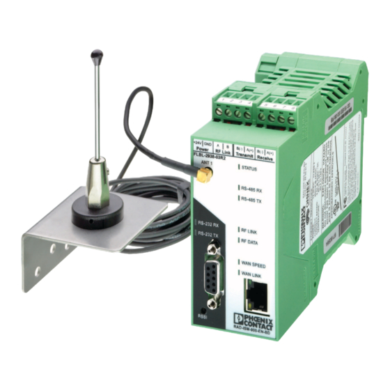
RS-485 2-wire connection RS-422 4-wire connection – + Power RF Link Transmit Receive Power RF Link Transmit Receive FLBL-2938-03R2 FLBL-2938-03R2 RAD-ISM-900-EN-BD RAD-ISM-900-EN-BD Figure 3-7 RS-422/485 2-wire and 4-wire connections 3-10 PHOENIX CONTACT 2476_en_I RSPSupply - 1-888-532-2706 - www.RSPSupply.com http://www.RSPSupply.com/p-12970-Phoenix-Contact-2900016-Radio-900-MHz-Ethernet-Radio.aspx... -
Page 35: Antenna Connections
T r a L i n - 0 3 - 2 9 N - B 0 - E - 9 0 D - I MCX Plug Figure 3-8 Antenna connection 3-11 2476_en_I PHOENIX CONTACT RSPSupply - 1-888-532-2706 - www.RSPSupply.com http://www.RSPSupply.com/p-12970-Phoenix-Contact-2900016-Radio-900-MHz-Ethernet-Radio.aspx... - Page 36 RAD-ISM-900-EN-BD… 3-12 PHOENIX CONTACT 2476_en_I RSPSupply - 1-888-532-2706 - www.RSPSupply.com http://www.RSPSupply.com/p-12970-Phoenix-Contact-2900016-Radio-900-MHz-Ethernet-Radio.aspx...
- Page 37 Ethernet Port..................4-17 4.13.2 Serial Ports ..................4-18 4.13.3 Data Streaming.................. 4-18 4.14 Passwords......................4-20 4.15 Store and Retrieve Settings................4-21 4.16 Performance..................... 4-22 4.17 Maintenance..................... 4-24 4.18 Monitoring/Reports ................... 4-26 2476_en_I PHOENIX CONTACT RSPSupply - 1-888-532-2706 - www.RSPSupply.com http://www.RSPSupply.com/p-12970-Phoenix-Contact-2900016-Radio-900-MHz-Ethernet-Radio.aspx...
- Page 38 RAD-ISM-900-EN-BD… PHOENIX CONTACT 2476_en_I RSPSupply - 1-888-532-2706 - www.RSPSupply.com http://www.RSPSupply.com/p-12970-Phoenix-Contact-2900016-Radio-900-MHz-Ethernet-Radio.aspx...
-
Page 39: Configuring A Pc To Communicate With The Radio
Wait approximately 10 seconds for the radio to boot up. Enter the following IP address into the “Address” field of the browser https://192.168.254.254 Enter the default case-sensitive credentials: Username: Admin Password: admin 2476_en_I PHOENIX CONTACT RSPSupply - 1-888-532-2706 - www.RSPSupply.com http://www.RSPSupply.com/p-12970-Phoenix-Contact-2900016-Radio-900-MHz-Ethernet-Radio.aspx... -
Page 40: Viewing Device Information
“LAN Configuration” on page 4-8. The new IP address must be known in order to gain access to the radio in the future. Viewing Device Information – After signing in, the home page shows the following basic information. Figure 4-3 “Home” screen showing device configuration PHOENIX CONTACT 2476_en_I RSPSupply - 1-888-532-2706 - www.RSPSupply.com http://www.RSPSupply.com/p-12970-Phoenix-Contact-2900016-Radio-900-MHz-Ethernet-Radio.aspx... -
Page 41: General Device Information
Radio MAC Address: There are separate MAC addresses for the radio and the physical Ethernet port. This is the MAC address for the MOTR-9 radio. Serial Number: This is the manufacturer’s serial number of the radio. 2476_en_I PHOENIX CONTACT RSPSupply - 1-888-532-2706 - www.RSPSupply.com http://www.RSPSupply.com/p-12970-Phoenix-Contact-2900016-Radio-900-MHz-Ethernet-Radio.aspx... -
Page 42: Local Diagnostics
This screen mimics the LEDs on the radio. For more information on the status LEDs, see “LED indicators” on page 6-3. Figure 4-5 “Local Diagnostics” screen PHOENIX CONTACT 2476_en_I RSPSupply - 1-888-532-2706 - www.RSPSupply.com http://www.RSPSupply.com/p-12970-Phoenix-Contact-2900016-Radio-900-MHz-Ethernet-Radio.aspx... -
Page 43: General Configuration
If no functions are performed for 10 minutes, the program will exit and all parameters must be re-configured. It is generally good practice to click the “Submit” button after all parameters are entered on each screen. 2476_en_I PHOENIX CONTACT RSPSupply - 1-888-532-2706 - www.RSPSupply.com http://www.RSPSupply.com/p-12970-Phoenix-Contact-2900016-Radio-900-MHz-Ethernet-Radio.aspx... -
Page 44: Lan Configuration
To access the Internet though this device, enter the IP address of the domain name server(s) under DNS 1 and DNS 2. Click the “Submit” button to write the configuration to the radio. PHOENIX CONTACT 2476_en_I RSPSupply - 1-888-532-2706 - www.RSPSupply.com... -
Page 45: Snmp Configuration
SNMP Agent: To disable SNMP, click Disable. SNMP v2c is enabled by default with the following settings: Table 4-1 Default SNMP settings Community Source Access Control Public 192.168.254.1 Read only Private 192.168.254.1 Read/Write 192.168.254.1 Notify 2476_en_I PHOENIX CONTACT RSPSupply - 1-888-532-2706 - www.RSPSupply.com http://www.RSPSupply.com/p-12970-Phoenix-Contact-2900016-Radio-900-MHz-Ethernet-Radio.aspx... -
Page 46: Configuring The Network Filter
This uses up bandwidth and may pose a security risk. The Network Filter allows a user to ensure only packets destined for remote devices connected via the radio link are sent over- the-air. 4-10 PHOENIX CONTACT 2476_en_I RSPSupply - 1-888-532-2706 - www.RSPSupply.com http://www.RSPSupply.com/p-12970-Phoenix-Contact-2900016-Radio-900-MHz-Ethernet-Radio.aspx... - Page 47 Network Filter Logging. Occurrences of a blocked packet will be logged in the System Log. Note that only one entry is logged for all occurrences of a blocked packet per rule. 4-11 2476_en_I PHOENIX CONTACT RSPSupply - 1-888-532-2706 - www.RSPSupply.com http://www.RSPSupply.com/p-12970-Phoenix-Contact-2900016-Radio-900-MHz-Ethernet-Radio.aspx...
-
Page 48: Configuring The Rad-Ism-900-En-Bd
Be sure to enter the slave/repeater radio’s IP/MAC addresses in addition to the end Ethernet devices. 4.10 Configuring the RAD-ISM-900-EN-BD… To configure the radio parameters, click on “Configuration… Radio… Settings” in the left navigation column. Figure 4-10 “Radio - Settings” screen 4-12 PHOENIX CONTACT 2476_en_I RSPSupply - 1-888-532-2706 - www.RSPSupply.com http://www.RSPSupply.com/p-12970-Phoenix-Contact-2900016-Radio-900-MHz-Ethernet-Radio.aspx... -
Page 49: Network Settings
ID entered in the “Alternate Fixed Master ID 1” field. if the “Use Alternate Master ID” check box is enabled. If the radio is unable to link to Alternate Fixed Master ID 1, it will 4-13 2476_en_I PHOENIX CONTACT RSPSupply - 1-888-532-2706 - www.RSPSupply.com http://www.RSPSupply.com/p-12970-Phoenix-Contact-2900016-Radio-900-MHz-Ethernet-Radio.aspx... -
Page 50: Figure 4-11 "Apply Radio Changes" Button
This requires approximately 5 seconds. If the radio is rebooted, the reboot process requires approximately 2 minutes. Figure 4-11 “Apply Radio Changes” button 4-14 PHOENIX CONTACT 2476_en_I RSPSupply - 1-888-532-2706 - www.RSPSupply.com http://www.RSPSupply.com/p-12970-Phoenix-Contact-2900016-Radio-900-MHz-Ethernet-Radio.aspx... -
Page 51: Radio Security
Copy the key into all slave or repeater radios. They must have the same key in order to communicate. Figure 4-12 Static AES security screen Click the “Submit” button to write the configuration to the radio. 4-15 2476_en_I PHOENIX CONTACT RSPSupply - 1-888-532-2706 - www.RSPSupply.com http://www.RSPSupply.com/p-12970-Phoenix-Contact-2900016-Radio-900-MHz-Ethernet-Radio.aspx... -
Page 52: Frequency Blocking
An additional message appears (see Figure 4-14) prompting to click the “Apply Radio Changes” button. This will reboot the unit and the settings will take effect. Figure 4-14 “Apply Radio Changes” button 4-16 PHOENIX CONTACT 2476_en_I RSPSupply - 1-888-532-2706 - www.RSPSupply.com http://www.RSPSupply.com/p-12970-Phoenix-Contact-2900016-Radio-900-MHz-Ethernet-Radio.aspx... -
Page 53: I/O Ports
Two advanced functions are available. RS-485 RS-485 RS-232 RS-232 RAD-ISM-900-EN-BD RAD-ISM-900-EN-BD Master radio Slave radio Ethernet device Figure 4-15 Ethernet device to radio to radio serial data transfer 4-17 2476_en_I PHOENIX CONTACT RSPSupply - 1-888-532-2706 - www.RSPSupply.com http://www.RSPSupply.com/p-12970-Phoenix-Contact-2900016-Radio-900-MHz-Ethernet-Radio.aspx... -
Page 54: Serial Ports
There are two independent serial channels (1 and 2) that allow use of the two physical serial ports on each radio (RS-232 and a RS-422/485 port). The serial port function varies depending on the radio mode of operation. Serial data transmitted from a slave radio’s serial 4-18 PHOENIX CONTACT 2476_en_I RSPSupply - 1-888-532-2706 - www.RSPSupply.com http://www.RSPSupply.com/p-12970-Phoenix-Contact-2900016-Radio-900-MHz-Ethernet-Radio.aspx... - Page 55 Data Bits: Sets the number of bits that make up each character. Parity: Sets the error checking method. Stop Bits: Sets the number of bits that signify the end of a character. 4-19 2476_en_I PHOENIX CONTACT RSPSupply - 1-888-532-2706 - www.RSPSupply.com http://www.RSPSupply.com/p-12970-Phoenix-Contact-2900016-Radio-900-MHz-Ethernet-Radio.aspx...
-
Page 56: Data Streaming
Packet mode: Collects entire packet before sending data over the air. Recommended for smaller data transfers and where a short delay in a packet at the controller could cause an error, e.g., Ethernet IP. 4-20 PHOENIX CONTACT 2476_en_I RSPSupply - 1-888-532-2706 - www.RSPSupply.com http://www.RSPSupply.com/p-12970-Phoenix-Contact-2900016-Radio-900-MHz-Ethernet-Radio.aspx... -
Page 57: Passwords
To change or set passwords, click on “Configuration… Passwords” in the left navigation column. Figure 4-20 “Configuration - Password Modification” screen To change either password, the appropriate password must be entered in all three fields. Click the “Submit” button when finished. 4-21 2476_en_I PHOENIX CONTACT RSPSupply - 1-888-532-2706 - www.RSPSupply.com http://www.RSPSupply.com/p-12970-Phoenix-Contact-2900016-Radio-900-MHz-Ethernet-Radio.aspx... -
Page 58: Store And Retrieve Settings
A passphrase is required to protect/validate the file before it can be saved or retrieved from the PC. It prevents unauthorized users from applying the system configuration file to an unauthorized node to gain access to the network. 4-22 PHOENIX CONTACT 2476_en_I RSPSupply - 1-888-532-2706 - www.RSPSupply.com http://www.RSPSupply.com/p-12970-Phoenix-Contact-2900016-Radio-900-MHz-Ethernet-Radio.aspx... -
Page 59: Performance
Each section contains a field to set the refresh interval (in seconds) of the page. Figure 4-22 “LAN Performance” screen Figure 4-23 “Serial Performance” screen 4-23 2476_en_I PHOENIX CONTACT RSPSupply - 1-888-532-2706 - www.RSPSupply.com http://www.RSPSupply.com/p-12970-Phoenix-Contact-2900016-Radio-900-MHz-Ethernet-Radio.aspx... -
Page 60: Figure 4-24 "Radio Performance" Screen
Repeat Frames Dropped: The number of frames that were dropped without being successfully received by another radio because the maximum number of retries was reached. A high number of dropped frames may indicate a high level of interference (repeaters only). 4-24 PHOENIX CONTACT 2476_en_I RSPSupply - 1-888-532-2706 - www.RSPSupply.com http://www.RSPSupply.com/p-12970-Phoenix-Contact-2900016-Radio-900-MHz-Ethernet-Radio.aspx... -
Page 61: Maintenance
To access the “Utilities” screen, click on “Maintenance… Network Utilities” screen in the left navigation column. The screen includes a field to enter an IP address or host name. Click the “Ping” button to find out if it is online and functional. 4-25 2476_en_I PHOENIX CONTACT RSPSupply - 1-888-532-2706 - www.RSPSupply.com http://www.RSPSupply.com/p-12970-Phoenix-Contact-2900016-Radio-900-MHz-Ethernet-Radio.aspx... - Page 62 928 MHz band to take a measurement of the RF noise on each channel. The average and peak measurements will be displayed. For accurate measurements, all other RAD-ISM-900-EN-BD… devices in the network should be powered down to prevent the radio transmissions from being measured. 4-26 PHOENIX CONTACT 2476_en_I RSPSupply - 1-888-532-2706 - www.RSPSupply.com http://www.RSPSupply.com/p-12970-Phoenix-Contact-2900016-Radio-900-MHz-Ethernet-Radio.aspx...
-
Page 63: Monitoring/Reports
5 seconds. Otherwise, this field will display inactive. – Supply (Battery) Voltage: Displays the voltage of the supply that is currently powering the device. – Temperature: Displays the temperature of the device in degrees Celsius. 4-27 2476_en_I PHOENIX CONTACT RSPSupply - 1-888-532-2706 - www.RSPSupply.com http://www.RSPSupply.com/p-12970-Phoenix-Contact-2900016-Radio-900-MHz-Ethernet-Radio.aspx... -
Page 64: Figure 4-31 "Monitoring - Bridging Status" Screen
RAD-ISM-900-EN-BD… Figure 4-31 “Monitoring - Bridging Status” screen Click on “Monitoring/Reports… Bridging Status” to review statistics on the interface between the radio and Ethernet connection. 4-28 PHOENIX CONTACT 2476_en_I RSPSupply - 1-888-532-2706 - www.RSPSupply.com http://www.RSPSupply.com/p-12970-Phoenix-Contact-2900016-Radio-900-MHz-Ethernet-Radio.aspx... - Page 65 Digital Output Module ................ 5-22 5.6.5 Combination Input/Output Module ............. 5-23 5.6.6 Digital Pulse Input Module ..............5-24 5.6.7 Digital Pulse Output Module .............. 5-27 Accessing the XML file ..................5-28 2476_en_I PHOENIX CONTACT RSPSupply - 1-888-532-2706 - www.RSPSupply.com http://www.RSPSupply.com/p-12970-Phoenix-Contact-2900016-Radio-900-MHz-Ethernet-Radio.aspx...
- Page 66 RAD-ISM-900-EN-BD… PHOENIX CONTACT 2476_en_I RSPSupply - 1-888-532-2706 - www.RSPSupply.com http://www.RSPSupply.com/p-12970-Phoenix-Contact-2900016-Radio-900-MHz-Ethernet-Radio.aspx...
-
Page 67: Bus Configuration For I/O Modules (Rad-Ism-900-En-Bd-Bus Only)
RAD-ISM-900-EN-BD-BUS radios in slave mode. – Master PLC connects to the radio’s serial port and uses Modbus RTU – Master PLC connects to the radio’s Ethernet port and uses Modbus TCP 2476_en_I PHOENIX CONTACT RSPSupply - 1-888-532-2706 - www.RSPSupply.com http://www.RSPSupply.com/p-12970-Phoenix-Contact-2900016-Radio-900-MHz-Ethernet-Radio.aspx... -
Page 68: I/O System Configuration Overview
Modbus RTU commands. A serial Modbus RTU master cannot use the Modbus gateway function to talk to other Modbus TCP-based I/O. c) The radio must be configured as a master. PHOENIX CONTACT 2476_en_I RSPSupply - 1-888-532-2706 - www.RSPSupply.com http://www.RSPSupply.com/p-12970-Phoenix-Contact-2900016-Radio-900-MHz-Ethernet-Radio.aspx... -
Page 69: Configuring Radios Connected To I/O
The I/O will only fail to the fault off condition when the timeout setting value is reached. Enter a value of “0” will disable the watchdog, and the fault condition will also be disabled. 2476_en_I PHOENIX CONTACT RSPSupply - 1-888-532-2706 - www.RSPSupply.com http://www.RSPSupply.com/p-12970-Phoenix-Contact-2900016-Radio-900-MHz-Ethernet-Radio.aspx... - Page 70 I/O: either a single Ethernet master source or a single serial source, but NOT both. If two I/O control sources are assigned to the I/O stream, the error message shown in Figure 5-3 is generated. PHOENIX CONTACT 2476_en_I RSPSupply - 1-888-532-2706 - www.RSPSupply.com...
-
Page 71: Configuring Radios Connected To The Plc /Modbus Master
“Serial Ports” on page 4-18). Ensure that there is only one source controlling the I/O: either a single Ethernet master source, or a single serial source, but NOT both on the same communications stream. 2476_en_I PHOENIX CONTACT RSPSupply - 1-888-532-2706 - www.RSPSupply.com http://www.RSPSupply.com/p-12970-Phoenix-Contact-2900016-Radio-900-MHz-Ethernet-Radio.aspx... -
Page 72: I/O Module Descriptions
This module has two configurable pulse or frequency outputs. A 4-position DIP switch inside the module is used to set the mode of each channel as well as the speed (high or low). PHOENIX CONTACT 2476_en_I RSPSupply - 1-888-532-2706 - www.RSPSupply.com... -
Page 73: Connecting And Configuring The I/O Modules
Module #5 raw analog inputs 89-96 Reserved Reserved Module #5 raw analog outputs 97-104 Module #6 digital outputs Module #6 digital inputs Module #6 raw analog inputs 105-112 Reserved Reserved Module #6 raw analog outputs 2476_en_I PHOENIX CONTACT RSPSupply - 1-888-532-2706 - www.RSPSupply.com http://www.RSPSupply.com/p-12970-Phoenix-Contact-2900016-Radio-900-MHz-Ethernet-Radio.aspx... - Page 74 Reserved Reserved Module #4 digital inputs Reserved Reserved Module #5 digital inputs Reserved Reserved Module #6 digital inputs Reserved Reserved Module #7 digital inputs Reserved Reserved Module #8 digital inputs 5-10 PHOENIX CONTACT 2476_en_I RSPSupply - 1-888-532-2706 - www.RSPSupply.com http://www.RSPSupply.com/p-12970-Phoenix-Contact-2900016-Radio-900-MHz-Ethernet-Radio.aspx...
- Page 75 Reserved Reserved Module #3 ID Reserved Reserved Module #4 ID Reserved Reserved Module #5 ID Reserved Reserved Module #6 ID Reserved Reserved Module #7 ID Reserved Reserved Module #8 ID 5-11 2476_en_I PHOENIX CONTACT RSPSupply - 1-888-532-2706 - www.RSPSupply.com http://www.RSPSupply.com/p-12970-Phoenix-Contact-2900016-Radio-900-MHz-Ethernet-Radio.aspx...
- Page 76 Module #3 Input 1 MSW Value (Pulse mode only) Module #3 Input 1 LSW Value Store (Pulse mode only) Module #3 Input 1 MSW Value Store (Pulse mode only) Module #3 Input 2 LSW Value 5-12 PHOENIX CONTACT 2476_en_I RSPSupply - 1-888-532-2706 - www.RSPSupply.com http://www.RSPSupply.com/p-12970-Phoenix-Contact-2900016-Radio-900-MHz-Ethernet-Radio.aspx...
- Page 77 Module #5 Input 2 MSW Value Store (Pulse mode only) Module #5 Output 1 LSW Value Module #5 Output 1 MSW Value (Pulse mode only) Module #5 Output 1 Absolute or Differential Operation LSW 5-13 2476_en_I PHOENIX CONTACT RSPSupply - 1-888-532-2706 - www.RSPSupply.com http://www.RSPSupply.com/p-12970-Phoenix-Contact-2900016-Radio-900-MHz-Ethernet-Radio.aspx...
- Page 78 Module #7 Output 2 Absolute or Differential Operation LSW Module #7 Output 2 Absolute or Differential Operation MSW 129 Module #8 Input 1 Value Control Bit Module #8 Input 1 LSW Value 5-14 PHOENIX CONTACT 2476_en_I RSPSupply - 1-888-532-2706 - www.RSPSupply.com http://www.RSPSupply.com/p-12970-Phoenix-Contact-2900016-Radio-900-MHz-Ethernet-Radio.aspx...
- Page 79 Module #8 Output 2 LSW Value Module #8 Output 2 MSW Value (Pulse mode only) Module #8 Output 1 Absolute or Differential Operation LSW Module #8 Output 1 Absolute or Differential Operation MSW 5-15 2476_en_I PHOENIX CONTACT RSPSupply - 1-888-532-2706 - www.RSPSupply.com http://www.RSPSupply.com/p-12970-Phoenix-Contact-2900016-Radio-900-MHz-Ethernet-Radio.aspx...
-
Page 80: Rotary Switches
5.5.1 Digital Channels A digital output channel can be turned on by writing a “1” to the digital output register, and off by writing a “0” to the output register. 5-16 PHOENIX CONTACT 2476_en_I RSPSupply - 1-888-532-2706 - www.RSPSupply.com http://www.RSPSupply.com/p-12970-Phoenix-Contact-2900016-Radio-900-MHz-Ethernet-Radio.aspx... -
Page 81: Analog Channel Scaling
However, if a new value of 3 were written, the pulse module would produce enough pulses to wrap the 32-bit register around until it is reset to 0 and then deliver 3 more pulses. Therefore, the pulse register should be cleared periodically. 5-17 2476_en_I PHOENIX CONTACT RSPSupply - 1-888-532-2706 - www.RSPSupply.com http://www.RSPSupply.com/p-12970-Phoenix-Contact-2900016-Radio-900-MHz-Ethernet-Radio.aspx... - Page 82 If using an OPC server, it may not write the clear register values with a single instruction. Use differential mode if the OPC server commands cannot clear the counter. There is no need to clear counters in differential mode. 5-18 PHOENIX CONTACT 2476_en_I RSPSupply - 1-888-532-2706 - www.RSPSupply.com http://www.RSPSupply.com/p-12970-Phoenix-Contact-2900016-Radio-900-MHz-Ethernet-Radio.aspx...
-
Page 83: Wiring And Fail Condition Dip Switches For The I/O Modules
Wiring and Fail Condition DIP Switches for the I/O Modules 5.6.1 Analog Input Module If using the Analog Input Module, use the wiring diagram shown in Figure 5-5. Figure 5-5 RAD-IN-4A-I Analog Input Module wire diagram 5-19 2476_en_I PHOENIX CONTACT RSPSupply - 1-888-532-2706 - www.RSPSupply.com http://www.RSPSupply.com/p-12970-Phoenix-Contact-2900016-Radio-900-MHz-Ethernet-Radio.aspx... -
Page 84: Digital Input Module
RAD-ISM-900-EN-BD… 5.6.2 Digital Input Module If using a Digital (Discrete) Input Module, use the wiring diagram shown in Figure 5-6. Figure 5-6 RAD-IN-8D Digital Input Module wire diagram 5-20 PHOENIX CONTACT 2476_en_I RSPSupply - 1-888-532-2706 - www.RSPSupply.com http://www.RSPSupply.com/p-12970-Phoenix-Contact-2900016-Radio-900-MHz-Ethernet-Radio.aspx... -
Page 85: Analog Output Module
Off to a current value of approximately 2 mA. Release the top part of the housing to access the internal DIP switches. Figure 5-7 RAD-OUT-4A-I Analog Output Module wire diagram 5-21 2476_en_I PHOENIX CONTACT RSPSupply - 1-888-532-2706 - www.RSPSupply.com http://www.RSPSupply.com/p-12970-Phoenix-Contact-2900016-Radio-900-MHz-Ethernet-Radio.aspx... -
Page 86: Digital Output Module
RF link is lost. The options are Maintain Last State or Fault Off (open circuit). Release the top part of the housing to access the internal DIP switches. Figure 5-8 RAD-IN-OUT-8D-REL Digital Output Module wire diagram 5-22 PHOENIX CONTACT 2476_en_I RSPSupply - 1-888-532-2706 - www.RSPSupply.com http://www.RSPSupply.com/p-12970-Phoenix-Contact-2900016-Radio-900-MHz-Ethernet-Radio.aspx... -
Page 87: Combination Input/Output Module
RF link is lost. The options are Maintain Last State or Fault Off (open circuit). Release the top part of the housing to access the internal DIP switches. Figure 5-9 RAD-OUT-8D-REL Digital Output Module wire diagram 5-23 2476_en_I PHOENIX CONTACT RSPSupply - 1-888-532-2706 - www.RSPSupply.com http://www.RSPSupply.com/p-12970-Phoenix-Contact-2900016-Radio-900-MHz-Ethernet-Radio.aspx... -
Page 88: Digital Pulse Input Module
DIP Switch Settings Refer to Figure 5-9 on page 5-23 for DIP switch configurations. 5-24 PHOENIX CONTACT 2476_en_I RSPSupply - 1-888-532-2706 - www.RSPSupply.com http://www.RSPSupply.com/p-12970-Phoenix-Contact-2900016-Radio-900-MHz-Ethernet-Radio.aspx... - Page 89 If the pulse signal is expected to be of negative polarity with respect to ground, set the module to a different input. If the signal is to remain positive at all times, set it to single ended. 5-25 2476_en_I PHOENIX CONTACT RSPSupply - 1-888-532-2706 - www.RSPSupply.com http://www.RSPSupply.com/p-12970-Phoenix-Contact-2900016-Radio-900-MHz-Ethernet-Radio.aspx...
-
Page 90: Figure 5-11 Description Of Rad-In-2Cnt Digital Pulse Input Module Leds
There are four diagnostic LEDs on the Digital Pulse Input Module. See Figure 5-11 for the meaning of each LED. Figure 5-11 Description of RAD-IN-2CNT Digital Pulse Input Module LEDs 5-26 PHOENIX CONTACT 2476_en_I RSPSupply - 1-888-532-2706 - www.RSPSupply.com http://www.RSPSupply.com/p-12970-Phoenix-Contact-2900016-Radio-900-MHz-Ethernet-Radio.aspx... -
Page 91: Digital Pulse Output Module
PLC value written to it. If frequency mode is selected, the pulse output module will generate pulses with a 50% duty cycle. In frequency mode, the low or high speed switch setting is ignored. 5-27 2476_en_I PHOENIX CONTACT RSPSupply - 1-888-532-2706 - www.RSPSupply.com http://www.RSPSupply.com/p-12970-Phoenix-Contact-2900016-Radio-900-MHz-Ethernet-Radio.aspx... -
Page 92: Accessing The Xml File
To access the file using a custom program, such as a Microsoft Excel spreadsheet, enter the IP address of the radio to be accessed in the following format: – https://aaa.bbb.ccc.ddd/iodata.xml 5-28 PHOENIX CONTACT 2476_en_I RSPSupply - 1-888-532-2706 - www.RSPSupply.com http://www.RSPSupply.com/p-12970-Phoenix-Contact-2900016-Radio-900-MHz-Ethernet-Radio.aspx... - Page 93 Bus Configuration for I/O Modules (RAD-ISM-900-EN-BD-BUS only) Figure 5-14 is an example of how the data is displayed for two I/O modules with rotary switch settings 5 and 6: Figure 5-14 Example of data display 5-29 2476_en_I PHOENIX CONTACT RSPSupply - 1-888-532-2706 - www.RSPSupply.com http://www.RSPSupply.com/p-12970-Phoenix-Contact-2900016-Radio-900-MHz-Ethernet-Radio.aspx...
- Page 94 RAD-ISM-900-EN-BD… 5-30 PHOENIX CONTACT 2476_en_I RSPSupply - 1-888-532-2706 - www.RSPSupply.com http://www.RSPSupply.com/p-12970-Phoenix-Contact-2900016-Radio-900-MHz-Ethernet-Radio.aspx...
- Page 95 Troubleshooting ..........................6-3 LED indicators ....................6-3 RSSI (Received Signal Strength Indicator)............6-4 General Troubleshooting ..................6-5 Resetting the IP Address ..................6-6 6.4.1 DOS command ..................6-6 6.4.2 Hardware Reset................... 6-6 2476_en_I PHOENIX CONTACT RSPSupply - 1-888-532-2706 - www.RSPSupply.com http://www.RSPSupply.com/p-12970-Phoenix-Contact-2900016-Radio-900-MHz-Ethernet-Radio.aspx...
- Page 96 RAD-ISM-900-EN-BD… PHOENIX CONTACT 2476_en_I RSPSupply - 1-888-532-2706 - www.RSPSupply.com http://www.RSPSupply.com/p-12970-Phoenix-Contact-2900016-Radio-900-MHz-Ethernet-Radio.aspx...
-
Page 97: Troubleshooting
Data is being transferred/received WAN Speed Green 100Base-T connection 10Base-T connection WAN Link Green Flashing Data is detected on Ethernet port Typical application error is an invalid configuration Not applicable for RAD-ISM-900-EN-BD/B 2476_en_I PHOENIX CONTACT RSPSupply - 1-888-532-2706 - www.RSPSupply.com http://www.RSPSupply.com/p-12970-Phoenix-Contact-2900016-Radio-900-MHz-Ethernet-Radio.aspx... -
Page 98: Rssi (Received Signal Strength Indicator)
Positive probe (–) to RSSI connector Figure 6-2 RSSI voltage strength check 500 kbps 250 kbps 125 kbps -100 -105 1.50 2.00 2.50 3.00 3.50 Volts Figure 6-3 Signal strength to voltage comparison PHOENIX CONTACT 2476_en_I RSPSupply - 1-888-532-2706 - www.RSPSupply.com http://www.RSPSupply.com/p-12970-Phoenix-Contact-2900016-Radio-900-MHz-Ethernet-Radio.aspx... -
Page 99: General Troubleshooting
Install larger gain antenna (and/or decrease coaxial cable loss). Check the power supply to ensure sufficient current capacity. Make sure the center pin of the antenna’s coaxial cable is not shorted to ground. 2476_en_I PHOENIX CONTACT RSPSupply - 1-888-532-2706 - www.RSPSupply.com http://www.RSPSupply.com/p-12970-Phoenix-Contact-2900016-Radio-900-MHz-Ethernet-Radio.aspx... -
Page 100: Resetting The Ip Address
Disconnect power from the radio. Insert a jumper across pins 2 and 3 on the DB-9 RS-232 port. Reconnect power. Once startup is complete, remove the jumper. PHOENIX CONTACT 2476_en_I RSPSupply - 1-888-532-2706 - www.RSPSupply.com http://www.RSPSupply.com/p-12970-Phoenix-Contact-2900016-Radio-900-MHz-Ethernet-Radio.aspx... - Page 101 After approximately 10 seconds, release the reset button and allow the radio to reboot. Once rebooted, the radio will return to the factory password defaults and an IP address of 192.168.254.254. For technical support, contact Phoenix Contact Technical Service. Please have the model number of the radio available. 2476_en_I PHOENIX CONTACT RSPSupply - 1-888-532-2706 - www.RSPSupply.com...
- Page 102 RAD-ISM-900-EN-BD… PHOENIX CONTACT 2476_en_I RSPSupply - 1-888-532-2706 - www.RSPSupply.com http://www.RSPSupply.com/p-12970-Phoenix-Contact-2900016-Radio-900-MHz-Ethernet-Radio.aspx...
- Page 103 This section informs you about – Ordering information – Technical data Technical and Ordering Data ......................7-3 Ordering Data ..................... 7-3 7.1.1 Products ....................7-3 7.1.2 Accessories ..................7-3 Technical Data ....................7-4 2476_en_I PHOENIX CONTACT RSPSupply - 1-888-532-2706 - www.RSPSupply.com http://www.RSPSupply.com/p-12970-Phoenix-Contact-2900016-Radio-900-MHz-Ethernet-Radio.aspx...
- Page 104 RAD-ISM-900-EN-BD… PHOENIX CONTACT 2476_en_I RSPSupply - 1-888-532-2706 - www.RSPSupply.com http://www.RSPSupply.com/p-12970-Phoenix-Contact-2900016-Radio-900-MHz-Ethernet-Radio.aspx...
-
Page 105: Ordering Data
Cable, 7.6 m (25 ft.) RG213 with type N connectors (male) RAD-CAB-RG213-25 2867597 Surge protection, bulkhead mount for 900 MHz radio CN-UB-280DC-BB-ASSY 5603859 Adapter cable, 1.2 m (4 ft.) RG316 with type N (male) and MCX (male) RAD-CON-MCX90-N-SS 2885207 connectors 2476_en_I PHOENIX CONTACT RSPSupply - 1-888-532-2706 - www.RSPSupply.com http://www.RSPSupply.com/p-12970-Phoenix-Contact-2900016-Radio-900-MHz-Ethernet-Radio.aspx... -
Page 106: Technical Data
250 kbps: -98 dBm 125 kbps: -102 dBm RSSI test point 0 … 3.5 V DC Approval/Conformance FCC/IC Part 15, Section 247 Class I, Div. 2 Groups A, B, C, D PHOENIX CONTACT 2476_en_I RSPSupply - 1-888-532-2706 - www.RSPSupply.com http://www.RSPSupply.com/p-12970-Phoenix-Contact-2900016-Radio-900-MHz-Ethernet-Radio.aspx... -
Page 107: Structure Of Ip Addresses
The key factor is the number of “ones” before the first “zero.” The assignment of classes is shown in Table A-1. The empty cells in the table are not relevant to the network class and are already used for the network address. 2476_en_I PHOENIX CONTACT RSPSupply - 1-888-532-2706 - www.RSPSupply.com http://www.RSPSupply.com/p-12970-Phoenix-Contact-2900016-Radio-900-MHz-Ethernet-Radio.aspx... -
Page 108: Class Assignments
1 1 1 0 Identifier for multicast group 224.0.0.0 - 239.255.255.255 27 bits Class E 1 1 1 1 0 Reserved for future applications 240.0.0.0 - 247.255.255.255 Figure A-2 Structure of IP Addresses PHOENIX CONTACT 2476_en_I RSPSupply - 1-888-532-2706 - www.RSPSupply.com http://www.RSPSupply.com/p-12970-Phoenix-Contact-2900016-Radio-900-MHz-Ethernet-Radio.aspx... -
Page 109: Special Ip Addresses For Special Applications
IP address is created when the bits of the IP address and the bits of the subnet mask are ANDed. Because the subnetwork is only recognized by local devices, the corresponding IP address appears as a “normal” IP address to all the other devices. 2476_en_I PHOENIX CONTACT RSPSupply - 1-888-532-2706 - www.RSPSupply.com http://www.RSPSupply.com/p-12970-Phoenix-Contact-2900016-Radio-900-MHz-Ethernet-Radio.aspx... - Page 110 After ANDing, the software determines that the relevant subnetwork (01) does not correspond to the local subnetwork (11) and forwards the data telegram to a subnetwork router. Figure A-3 Example for a Class B Subnet Mask PHOENIX CONTACT 2476_en_I RSPSupply - 1-888-532-2706 - www.RSPSupply.com http://www.RSPSupply.com/p-12970-Phoenix-Contact-2900016-Radio-900-MHz-Ethernet-Radio.aspx...
-
Page 111: Examples For Subnet Masks And Computer Bits
3 Bits 255.255.255.240 4 Bits 255.255.255.224 5 Bits 255.255.255.192 6 Bits 255.255.255.128 7 Bits 255.255.2545.0 8 Bits 255.255.254.0 9 Bits 255.255.252.0 10 Bits 255.255.248.0 11 Bits 255.128.0.0 23 Bits 255.0.0.0 24 Bits 2476_en_I PHOENIX CONTACT RSPSupply - 1-888-532-2706 - www.RSPSupply.com http://www.RSPSupply.com/p-12970-Phoenix-Contact-2900016-Radio-900-MHz-Ethernet-Radio.aspx... - Page 112 RAD-ISM-900-EN-BD… PHOENIX CONTACT 2476_en_I RSPSupply - 1-888-532-2706 - www.RSPSupply.com http://www.RSPSupply.com/p-12970-Phoenix-Contact-2900016-Radio-900-MHz-Ethernet-Radio.aspx...
-
Page 113: List Of Figures
“LAN - IP Configuration” screen ............4-8 Figure 4-8: “LAN-SNMP Configuration” screen ............ 4-9 Figure 4-9: “LAN - Network Filter Configuration” screen ........4-11 Figure 4-10: “Radio - Settings” screen ..............4-12 2476_en_I PHOENIX CONTACT RSPSupply - 1-888-532-2706 - www.RSPSupply.com http://www.RSPSupply.com/p-12970-Phoenix-Contact-2900016-Radio-900-MHz-Ethernet-Radio.aspx... - Page 114 RAD-IN-2D-CNT Pulse Input Module wire diagram ......5-24 Figure 5-11: Description of RAD-IN-2CNT Digital Pulse Input Module LEDs ..5-26 Figure 5-12: RAD-OUT-2D-CNT Digital Pulse Output Module wire diagram ..5-27 PHOENIX CONTACT 2476_en_I RSPSupply - 1-888-532-2706 - www.RSPSupply.com http://www.RSPSupply.com/p-12970-Phoenix-Contact-2900016-Radio-900-MHz-Ethernet-Radio.aspx...
- Page 115 Appendix A Figure A-1: Location of bits within the IP address ..........A-1 Figure A-2: Structure of IP Addresses ..............A-2 Figure A-3: Example for a Class B Subnet Mask ..........A-4 2476_en_I PHOENIX CONTACT RSPSupply - 1-888-532-2706 - www.RSPSupply.com http://www.RSPSupply.com/p-12970-Phoenix-Contact-2900016-Radio-900-MHz-Ethernet-Radio.aspx...
- Page 116 RAD-ISM-900-EN-BD… PHOENIX CONTACT 2476_en_I RSPSupply - 1-888-532-2706 - www.RSPSupply.com http://www.RSPSupply.com/p-12970-Phoenix-Contact-2900016-Radio-900-MHz-Ethernet-Radio.aspx...
-
Page 117: List Of Tables
Troubleshooting Procedures .............. 6-5 Appendix A Table A-1: Class Assignments ................A-2 Table A-2: Network and User Class Bit Assignments.......... A-2 Table A-3: Examples for Subnet masks and computer bits ......... A-5 2476_en_I PHOENIX CONTACT RSPSupply - 1-888-532-2706 - www.RSPSupply.com http://www.RSPSupply.com/p-12970-Phoenix-Contact-2900016-Radio-900-MHz-Ethernet-Radio.aspx... - Page 118 RAD-ISM-900-EN-BD… PHOENIX CONTACT 2476_en_I RSPSupply - 1-888-532-2706 - www.RSPSupply.com http://www.RSPSupply.com/p-12970-Phoenix-Contact-2900016-Radio-900-MHz-Ethernet-Radio.aspx...
-
Page 119: Explanation Of Terms
Firewall A set of related programs located at a network gateway server that protects the resources of a network from other networks. Firmware The programming code that runs a device. 2476_en_I PHOENIX CONTACT RSPSupply - 1-888-532-2706 - www.RSPSupply.com http://www.RSPSupply.com/p-12970-Phoenix-Contact-2900016-Radio-900-MHz-Ethernet-Radio.aspx... - Page 120 Used much like a password, a passphrase simplifies the WEP encryption process by automatically generating the WEP encryption keys. Ping (Packet INternet An Internet utility used to determine whether a particular IP address is connected to the Groper) network. PHOENIX CONTACT 2476_en_I RSPSupply - 1-888-532-2706 - www.RSPSupply.com http://www.RSPSupply.com/p-12970-Phoenix-Contact-2900016-Radio-900-MHz-Ethernet-Radio.aspx...
- Page 121 A fixed address assigned to a computer or device that is connected to a network. Static Routing Forwarding data in a network via a fixed path. Subnet Mask An address code that determines the size of the network. 2476_en_I PHOENIX CONTACT RSPSupply - 1-888-532-2706 - www.RSPSupply.com http://www.RSPSupply.com/p-12970-Phoenix-Contact-2900016-Radio-900-MHz-Ethernet-Radio.aspx...
- Page 122 IP address assigned to each one. DNS is an alternative system for name resolution suitable for network computers with fixed IP addresses. B-10 PHOENIX CONTACT 2476_en_I RSPSupply - 1-888-532-2706 - www.RSPSupply.com http://www.RSPSupply.com/p-12970-Phoenix-Contact-2900016-Radio-900-MHz-Ethernet-Radio.aspx...
Need help?
Do you have a question about the MOTR-9 RAD-ISM-900-EN-BD and is the answer not in the manual?
Questions and answers