
Related Manuals for NED XCM40170DLMT2CXP


Summary of Contents for NED XCM40170DLMT2CXP
- Page 1 User Manual Line Scan Camera XCM40170DLMT2CXP 40170DLMT2CXP 40170DLMT2CXP 40170DLMT2CXP NIPPON ELECTRO-SENSORY DEVICES CORPORATION...
- Page 2 Directive on Waste Electrical and Electronic Equipment (WEEE) Please return all End of Life NED products to the distributor from whom the product was purchased for adequate recycling and / or disposal. All costs of returning the Product to NED are borne by the shipper.
- Page 3 Introduction Thank you for purchasing NED’s Line Scan Camera. We look forward to your continued custom in the future. For safety use For your protection, please read these safety instructions completely before operating the product and keep this manual for future reference.
- Page 4 Do not share the power supply with motor units or other devices that generate noise interference. Do not disconnect the camera while rewriting the embedded memory. When you change the exposure mode that is set at the NED factory, input control signal (Trigger packet) from the capture board. XCM40170DLMT2CXP...
- Page 5 Regardless of whether within the warranty period or not, our warranty does not cover compensation for missed opportunities for our customers, or our customers’ customers, caused by a fault of our products, nor for damage to products other than our own, or related business. UME-0064-01 XCM40170DLMT2CXP...
- Page 6 On request, arrangements can be made separately. Scope of Repair Service The above assumes business dealings and usage to take place in the customer’s region/country. In cases of business dealings and/or usage outside the customer’s region/country, separate consultation is required. XCM40170DLMT2CXP UME-0064-01...
-
Page 7: Table Of Contents
5.3.5 Setting Gamma Correction ..................29 5.3.6 Setting Analog Gain ....................29 5.3.7 Setting Digital Gain ....................30 5.3.8 Setting Digital Offset ....................30 5.3.9 Setting Exposure Mode ..................31 5.3.10 Setting Exposure Time ..................31 5.3.11 Setting Exposure-Readout Time ................. 32 UME-0064-01 XCM40170DLMT2CXP... - Page 8 7.2 Protecting Against Dust, Oil and Scratches ............. 56 7.3 Cleaning the Sensor Window ..................56 8 Troubleshooting ............... 57 8.1 When there is no Image ....................57 8.2 When Noise is present in the Image ................59 8.3 When the Camera becomes hot ................. 61 XCM40170DLMT2CXP UME-0064-01...
- Page 9 9 Others ................62 9.1 Notice ..........................62 9.2 Contact for support ..................... 62 9.3 Product Support ......................62 UME-0064-01 XCM40170DLMT2CXP...
-
Page 10: Product Outline
Up Link trigger semantics Device Discovery GenICam correspondence 1.2 Application Inspection of Transparent panels and PCBs Flat panel display inspection Inspection of glass and sheet-like objects Inspection of high speed moving objects This camera utilizes an Intelligent Transportation System Outdoor surveillance XCM40170DLMT2CXP UME-0064-01... -
Page 11: Image Sensor
Also, it comes as the output data of 2048 pixels with 14µm-square pixel equivalent from 170MHz by 2x2 pixels binning. 4096Pixels A line B line 2048 pixels with 14µm-square pixel equivalent by 2x2 pixels binning 2048Pixels 14um 14um UME-0064-01 XCM40170DLMT2CXP... -
Page 12: Performance Specifications
The Performance Specifications are shown in Table 1-4-1. It shows the data when the camera is operating at maximum scan rate, unless otherwise specified. Table 1-4-1 Performance Specifications Specifications Items XCM40170DLMT2CXP Number of Pixels 4096x2(Dual line) Pixel Size H x V (µm) 7 x 7 Sensor Length (mm) 28.672... - Page 13 5. Scan Direction Switching Note: *1) DN : Digital Number (8bit : 0-255) *2) Measurements were made at room temperature. Interface specifications Items XCM40170DLMT2CXP Bit Rate 2.5Gbps (CXP-2) Discovery Rate 1.25Gbps (CXP-1) (at Device discovery) Number of Links 2(2 cables):Dual mode 1(1 cable):Single mode...
-
Page 14: Camera Setting And Optical Interface
If using the front panel M4 mounting holes (4 places at the front, 8 places at the side), the screw length for fixing the camera should be less than 6mm. No X-, Y-axis orientation and tilt adjustment mechanism is available. Please prepare an adjustment mechanism if required. XCM40170DLMT2CXP UME-0064-01... - Page 15 C L I S B e e - S DIGITAL LINE SCAN CAMERA (Canare BCJ-FPC) Indicator POWER DC12-15V Power Connector (HIROSE HR10G-7R-6PB) 4-M4 DEEP 6 Nikon Fmont 4-M4 DEEP 6 (FB=46.5) (FRONT) (SIDE) 1-1/4"-20UNC DEEP 6 (BOTTOM) unit:mm Figure 2-2-1 Dimensions of the Camera UME-0064-01 XCM40170DLMT2CXP...
-
Page 16: Optical Interface
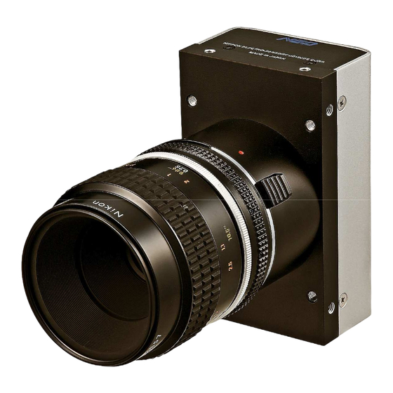
2.3 Optical Interface The XCM40170DLMT2CXP comes with an F-Mount as standard. 1) Quantities of light and the wavelength etc. of a source of light necessary to take the image for which the customer hopes are different according to the usage. The... -
Page 17: Hardware
We recommend that you use a standard approved cable. Refer to JIIA (http://jiia.org/cxp/) for more information about standard approved cables. As specifications for each manufacturer differs, please contact the cable manufacturer directly for details. UME-0064-01 XCM40170DLMT2CXP... -
Page 18: Input / Output Connectors And Indicator
Figure 3-2-1 Input/output Connectors and Indicator The pin assignment of the power supply connector is shown below. Figure 3-2-2 Power Supply Connector (HIROSE: HR10G -7R- 6PB) Round shape push-pull lock type Table 3-2-1 Pin Assignment of Power Supply Connector Name 12-15V 12-15V 12-15V XCM40170DLMT2CXP UME-0064-01... -
Page 19: Power Supply
* When the scan rate is close to 1.6s, the LED may flash orange and green alternately. When Acquisition Start and Stop are performed repeatedly, the green LED may appear to be flashing. * Moreover, when repeating the operation rapidly, the green LED may appear dark. UME-0064-01 XCM40170DLMT2CXP... -
Page 20: Camera Startup
“DCF” file. Open Intellicam from the Matrox Imaging Library ① From the Intellicam “File/Open” Menu, open “DefaultLineScan” ② If the contents of the DCF file are displayed, then discovery has been performed successfully. ③ XCM40170DLMT2CXP UME-0064-01... -
Page 21: Camera Control
0x10030/0x20030 Single CXP-2 / Dual CXP-2 Category Image Format Control : Binning Horizontal =2, 2048 Pixels Width 0x0000_A000 2048 / 4096 Binning Horizontal =1, 4096 Pixels Height 0x0000_A004 1 Line 1=Off / 2=2 Pixels binning Binning Horizontal 0x0000_A280 1 / 2 See 5.3.22 UME-0064-01 XCM40170DLMT2CXP... - Page 22 1=Gamma 0.45 / NED_GammaMode 0x0000_A258 0/1/2/3/4 2=Gamma 0.56 / 3=Negative Positive inversion / 4=Custom Gamma 0x0000_A25C 250 to 4000 γ0.250~4.000 Category NED Camera features : AnalogGain x1.00...x17.8 0x0000_A080 0 to 7 See 5.11 DigitalGain x1...x2(x0.003906/step) 0x0000_A084 0 to 511 See 5.11 -63...63(0.5DN/step at 8bit)
- Page 23 Pixel correction data reset to factory 0x0000_A260 ResetToFactoryDefault settings Category User Set Control : UserSet_ 0x0000_A0B8 UserSet data reset to factory settings ResetToFactoryDefault UserSet_Load 0x0000_A0BC Readout setup data in memory UserSet_Save 0x0000_A0C0 Store present setup data in memory UME-0064-01 XCM40170DLMT2CXP...
-
Page 24: Memory Setup Values (Factory Settings)
DigitalGain 0x0000_A084 x1.00 DigitalOffset 0x0000_A088 ExposureMode 0x0000_A08C FreeRun ExposureTimeCounter 0x0000_A094 10000 117.647µs Padding 0x0000_A098 2.129µs TestImageSelector 0x0000_A0A4 ReverseX 0x0000_A0B4 Forward Line Delay 0 LineDelay 0x0000_A0E4 (Not use line delay) PixelCorrectSetMode 0x0000_A0A8 Factory white (Factory Black) PixelCorrectSetLevel 0x0000_A0AC XCM40170DLMT2CXP UME-0064-01... -
Page 25: Programmable Exposure Time・ ・ ・ ・ Exposure-Readout Time Calculation Procedure25
ExposureTimeCounter : (0x0000_A094)= 10000 Padding: (0x0000_A098)= 0 Programmable Exposure Time =10000÷85.0=117.647µs Exposure-Readout Time =2.129+(0÷85.0)=2.129µs Scan Rate =117.647+2.129=119.776µs 5.3 Details on register system This explanation uses the Matrox Radient eV-CXP as an example. Run Intellicam (part of Matrox Imaging Library). ① UME-0064-01 XCM40170DLMT2CXP... - Page 26 Open the DCF file and the Feature Browser. ② Control the camera from the Features box. ③ In the case of the Matrox Radient, the list of registers is displayed in the window. Change the settings via the dropdown list or spinners. XCM40170DLMT2CXP UME-0064-01...
-
Page 27: Setting Linkconfig
5.3.2 Setting Horizontal Binning Sets horizontal binning. ・Register name Binning Horizontal 1 / 2(Binning Off:4096pixels / 2px Binning:2048pixels) ・VAL 2px Binning(2048 pixels) (Example) Binning Horizontal : 2 By setting value, it will change the width. UME-0064-01 XCM40170DLMT2CXP... -
Page 28: Setting Tdi Mode
(Dual line(average) / Single line A / Dual line(addition) / Single line B) Dual line mode(Additional average) (Example) NED_TDIMode : Dual line(average) 5.3.4 Setting Pixel Format Sets pixel format of camera. ・Register name PixelFormat Mono8 / Mono10 ・VAL (Example)Mono 8bit Pixel Format:Mono8 XCM40170DLMT2CXP UME-0064-01... -
Page 29: Setting Gamma Correction
Custom γ0.3 (Example) NED_GammaMode : Custom Gamma : 0.3 5.3.6 Setting Analog Gain Sets analog gain between x1 and x17.8. ・Register name AnalogGain x 1 ~ x 17.8 ・VAL Setting analog gain[X 5.2] (Example) AnalogGain : x 5.2(14.3dB) UME-0064-01 XCM40170DLMT2CXP... -
Page 30: Setting Digital Gain
Digital Gain : 1023 / (1023 – VAL ) ・Register name Digital Gain 0 (×1)~511 (×2) ・VAL (Example) Digital Gain: 255 (Setting digital gain 255(1023/(1023-255)=x1.33) 5.3.8 Setting Digital Offset Sets digital offset -127~+127(8bit:0.5DN/Step), -127~+127(10bit:2DN/Step) ・Register name DigitalOffset -127 ~ +127 ・VAL (Example) Digital Offset: 5 XCM40170DLMT2CXP UME-0064-01... -
Page 31: Setting Exposure Mode
Free run / External edge / External level ・VAL (Example) ExposureMode: Free run 5.3.10 Setting Exposure Time Sets the exposure time. ・Register name ExposureTimeCounter 915~1048575(Setting Counter) ・VAL (Example) ExposureTimeCounter:10000 The changes will be reflected in Integration Time and Scanrate. UME-0064-01 XCM40170DLMT2CXP... -
Page 32: Setting Exposure-Readout Time
Sets exposure-readout time. ・Register name Padding 0~1048575 ・VAL (Example) Padding:200 The changes will be reflected in Padding Time and Scanrate. 5.3.12 Generating Test Pattern Generates test pattern. ・Register name Test Image Selector Off / GreyHorizontalRamp ・VAL (Example) TestImageSelector: GreyHorizontalRamp XCM40170DLMT2CXP UME-0064-01... -
Page 33: Setting Pixel Readout Direction
/ check box (Reverse) ・VAL (Example) ReverseX : Check box 5.3.14 Setting Line Delay Sets line delay when TDI mode is “Dual line”. ・Register name LineDelay -1 / 0 / 1 ・VAL (Example)Line Delay 1 LineDelay : 1 UME-0064-01 XCM40170DLMT2CXP... -
Page 34: Setting Pixel Correction
: Factory white PixelCorrectSetLevel : 127 5.3.16 Getting User White Gets arbitrary user white data, save the memory. ・Register name PixelCorrectDataSave Execute() ・VAL 5.3.17 Getting User Black Gets arbitrary user black data, save the memory. ・Register name PixelCorrectDataSaveBlack Execute() ・VAL XCM40170DLMT2CXP UME-0064-01... -
Page 35: Reset User White-Black
5.3.20 Memory Load (Reads out the camera settings from the flash memory) Reads out the camera settings from the flash memory ・Register name User Set_Load Execute() ・VAL 5.3.21 Memory Save Stores current camera settings in the flash memory. ・Register name User Set_Save Execute() ・VAL UME-0064-01 XCM40170DLMT2CXP... -
Page 36: Setting Line Delay, Tdi Mode By The Horizontal Binning
- - Addition Improvement Responsivity (Output signal is digital added of 4pixels) Pixel size is 14x14um - - - - Not use - - - - - - - - Not use - - - - - - XCM40170DLMT2CXP UME-0064-01... -
Page 37: Digital Processing Flow In Fpga
③ Sets up the camera with the setting values from the flash memory. When this sequence finishes, the camera is ready to capture and output images. In order to output images, the Discovery procedure must be done from the frame grabber board. UME-0064-01 XCM40170DLMT2CXP... -
Page 38: Saving And Loading Camera Settings
Free Run (Programmable time setting) Not in use (Factory Setting) Ext Edge (External trigger edge+ Programmable External trigger ( Trigger packet ) is required time setting) Ext Level (External trigger level time setting) External trigger ( Trigger packet) is required XCM40170DLMT2CXP UME-0064-01... -
Page 39: Video Output Format
(in the case of some manufacturers, they may not be displayed) However, if the frame grabber does not support GenICam, this function is not available. UME-0064-01 XCM40170DLMT2CXP... -
Page 40: Exposure Mode And Timing Chart
2048pixels_ Single 12.05 Unit:µs ( ) scan ① ② ③ ④ ⑤ Exposure ① ② ③ ④ Readout Figure 5-9-1-1 Free Run Exposure Mode(In case of 4096 pixels) The data of Exposure (1) is read out at Readout (1) XCM40170DLMT2CXP UME-0064-01... - Page 41 ① ② ③ ④ ⑤ Exposure ① ② ③ Readout Figure 5-9-1-2 Free Run Exposure Mode(In case of 2048 pixels) The data of Exposure (1) is read out at Readout (1) UME-0064-01 XCM40170DLMT2CXP...
-
Page 42: External Trigger Exposure Mode (Trigger Edge)
E x p o su re ① ② ③ ① ② R e a d o u t Figure 5-9-2-1 External Trigger (Trigger Edge) Exposure Mode (In case of 4096 pixels) The data of Exposure (1) is read out at Readout (1) XCM40170DLMT2CXP UME-0064-01... - Page 43 ① ② ③ Trigger (CC1) Exposure ① ② ③ ① Readout Figure 5-9-2-2 External Trigger (Trigger Edge) Exposure Mode (In case of 2048 pixels) The data of Exposure (1) is read out at Readout (1) UME-0064-01 XCM40170DLMT2CXP...
-
Page 44: External Trigger Exposure Mode (Trigger Level)
( ) ① ③ ② Trigger (CC1) Exposure ① ② ③ ① ② Readout Figure 5-9-3-1 External Trigger (Trigger Level) Exposure Mode (In case of 4096 pixels) The data of Exposure (1) is read out at Readout (1) XCM40170DLMT2CXP UME-0064-01... - Page 45 ① ③ ② Trigger (CC1) Exposure ① ② ③ ① Readout Figure 5-9-3-2 External Trigger (Trigger Level) Exposure Mode (In case of 2048 pixels) The data of Exposure (1) is read out at Readout (1) ◆ UME-0064-01 XCM40170DLMT2CXP...
-
Page 46: Setting Offset
By setting the offset, you can set the Y-intercept arbitrarily. DF shows the digital offset value. The gradient of the line does not change. DF : Offset Value Output Amount of Incident Light (lx・s) Figure 5-10-2 Offset Adjustment Adjust amount of offset in accordance with the requirements of your camera system. XCM40170DLMT2CXP UME-0064-01... -
Page 47: Setting Gain
Gain a Gain b Gain c Amount of Incident Light (lx・s) Figure 5-11-1 PGA Gain Adjustment Gain and noise values are proportionally related. Adjust the amount of gain in accordance with the requirements of your camera system . UME-0064-01 XCM40170DLMT2CXP... - Page 48 Gain-Sensitivity is shown below. Table 5-11-1 Gain-Sensitivity Sensitivity AnalogGain Analog Amplifier (V/lx・s) x1.0 0.0dB x1.8 5.0dB x3.4 10.7dB x5.2 14.3dB x6.4 16.1dB x7.8 17.9dB x9.7 19.7dB 1213 x17.8 25.0dB 2225 Digital gain x1, Pixel correction:default(Factory white correction data, Correctionlevel 200DN /8-bit) XCM40170DLMT2CXP UME-0064-01...
-
Page 49: Pixel Correction
(10bit digital) Vin : Input data (digital) Vout : Output data (digital) The corrected data is expressed in the following equation. Vout=(Vin-Cal_bl) x Target_val / (Cal_wh-Cal_bl) Waveform before bit correction Output Pixel Number Waveform after bit correction Output Pixel Number Figure5-12-1 Waveform before and after bit correction UME-0064-01 XCM40170DLMT2CXP... -
Page 50: How To Perform Pixel Correction
At this time, please defocus a little to avoid being affected by the non-uniformity of the object. Run PixelCorrectDataSave ② Complete PixelCorrectDataSave : Background color is change into white ③ Setting PixelCorrectSetLevel (Correction level:8bit) ④ XCM40170DLMT2CXP UME-0064-01... -
Page 51: Test Pattern
This camera can generate a test pattern. Use the test pattern to verify the proper timing and connections between the camera and the frame grabber board. Figure 5-13-1 Test Pattern of XCM40170DLMT2CXP(4096pixels) Figure 5-13-2 Test Image of XCM40170DLMT2CXP(4096pixels) From pixel 0, 10bit data is output in order (0,1, 2, 3 … 1023, 0, 1, 2), repeating 4 times. - Page 52 Figure 5-13-3 Test Pattern of XCM40170DLMT2CXP(2048pixels) Figure 5-13-4 Test Image of XCM40170DLMT2CXP(2048pixels) From pixel 0, 10bit data is output in order (0,1, 2, 3 … 1023, 0, 1, 2), repeating 2 times. In case of 8bit, data is output in order (0,0,0, 0, 1, 1, 1, 1, 2, 2, 2, 2, 3, 3, 3, 3 … 255, 255, 255, 255), repeating 2 times.
-
Page 53: Confirming Camera Settings
② Make sure that the coaxial cables are connected to the frame grabber board correctly as follows. A 75Ω-type coaxial cable and connector must be used. The number of links and usable positions on the frame grabber board varies by board manufacturer. UME-0064-01 XCM40170DLMT2CXP... -
Page 54: After Power-On
Check the camera operation using the camera control software supplied with your frame grabber. For details please refer to your frame grabber’s manual. Capture images using a camera interface board utility. In the case of Matrox’s Radient eV-CXP, it is convenient to use Intellicam. Figure 6-2-1 Radient eV-CXP Window XCM40170DLMT2CXP UME-0064-01... -
Page 55: During Operation
(2) Are there dark lines in the direction of vertical scanning on the image? <Cause> <1> Dust on the sensor window Dust may get onto the sensor window from the inside or the outside of the camera. Remove the dust with air or a lens cleaner. UME-0064-01 XCM40170DLMT2CXP... -
Page 56: Sensor Handling Instructions
7.3 Cleaning the Sensor Window Dust: Can usually be removed by blowing the window surface using a compressed air blower. Oil: Wipe the window with a lint-free cloth wiper moistened with ethyl alcohol carefully and slowly. XCM40170DLMT2CXP UME-0064-01... -
Page 57: Troubleshooting
The sample software program is used to with the camera control the camera and is communicating successfully. To next page with the camera successfully. To next page To next page Confirm the communication software, the control protocol for the camera and commands. UME-0064-01 XCM40170DLMT2CXP... - Page 58 The optical axes of the camera and Check the light source. If the images are the image sensor are aligned. too dark, try to increase the light intensity, and vice versa. The camera could be faulty. Please contact us for assistance. XCM40170DLMT2CXP UME-0064-01...
-
Page 59: When Noise Is Present In The Image
(attached to a machine which applies stress to the cables). Check the condition of the camera cables and the power supply cable. The camera could be faulty. Please To next page contact us for assistance. UME-0064-01 XCM40170DLMT2CXP... - Page 60 When the camera gain is on a high level, bright spots occur without incident light. The camera could be faulty. Please Secondary radiation (rays) contact us for assistance. could cause bright spots, but this is not a malfunction. XCM40170DLMT2CXP UME-0064-01...
-
Page 61: When The Camera Becomes Hot
Allow sufficient air circulation around the camera to give it a longer product life. Keep the ambient temperature within the range of the specifications. The camera could be faulty. Please contact us for assistance. UME-0064-01 XCM40170DLMT2CXP... - Page 62 Contents of this document are subject to change without prior notice. Every care has been taken in the preparation of this User’s Manual. If you should discover any errors or omissions, please notify your nearest NED representative. 9.2 Contact for support...
- Page 63 Revision History Revision Date Changes 24 March 2016 Initial release UME-0064-01 XCM40170DLMT2CXP...
Need help?
Do you have a question about the XCM40170DLMT2CXP and is the answer not in the manual?
Questions and answers