Table of Contents
Advertisement
Quick Links
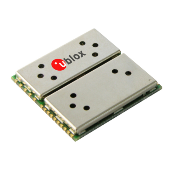
TIM-5H
u-blox 5 GPS and GALILEO Module
Hardware Integration Manual
Abstract
This document describes the hardware features and specifications of the
u-blox 5 based TIM-5H cost effective, high-performance GPS/GALILEO module.
Features include AssistNow Online and AssistNow Offline A-GPS services,
KickStart accelerated acquisition, SuperSense
acquisition and tracking sensitivity, precision timing and an innovative jamming-
resistant RF architecture. The 25.4 x 25.4 mm form factor of the successful
TIM-4 series is maintained, enabling easy migration. The TIM-5H supports
passive and active antennas.
your position is our focus
®
Indoor GPS providing best-in-class
u-blox AG
Zürcherstrasse 68
8800 Thalwil
Switzerland
www.u-blox.com
Phone +41 44 722 7444
Fax +41 44 722 7447
info@u-blox.com
Advertisement
Table of Contents

Related Manuals for Ublox TIM-5H


Summary of Contents for Ublox TIM-5H
- Page 1 Features include AssistNow Online and AssistNow Offline A-GPS services, ® KickStart accelerated acquisition, SuperSense Indoor GPS providing best-in-class acquisition and tracking sensitivity, precision timing and an innovative jamming- resistant RF architecture. The 25.4 x 25.4 mm form factor of the successful TIM-4 series is maintained, enabling easy migration. The TIM-5H supports passive and active antennas. your position is our focus...
- Page 2 your position is our focus TIM-5H Title Subtitle Hardware Integration Manual Doc Type Manual Doc Id GPS.G5-MS5-07015-A-1 Revision Date Name Status / Comments Index Initial Version 18/01/2008 TC Initial Release 16/04/2008 TG Addition of Hardware Description, Product Handling, Producgt Testing, Appendix 1 16/04/2008 TG Paste Mask This document and the use of any information contained therein, is subject to the acceptance of the u-blox terms and conditions. They can be downloaded from www.u-blox.com. u-blox makes no warranties based on ...
-
Page 3: Preface
Hardware Integration Manual: This Manual provides hardware design instructions and information on how to set up production and final product tests. How to use this Manual The TIM-5H Hardware Integration Manual provides the necessary information to successfully design in and configure these u-blox 5-based GPS/GALILEO receiver modules. For navigating this document please note the following: This manual has a modular structure. It is not necessary to read it from the beginning to the end. To help in ... - Page 4 Product information, technical documents and helpful FAQ can be accessed 24h a day. By E-mail If you have technical problems or cannot find the required information in the provided documents, contact the nearest of the Technical Support offices by email. Use our service pool email addresses rather than any personal email address of our staff. This makes sure that your request is processed as soon as possible. You will find the contact details at the end of the document. By Phone If an email contact is not the right choice to solve your problem or does not clearly answer your questions, call the nearest Technical Support office for assistance. You will find the contact details at the end of the document. Helpful Information when Contacting Technical Support When contacting Technical Support please have the following information ready: • Receiver type (e.g. TIM-5H) and firmware version (e.g. V4.00) • Receiver configuration • Clear description of your question or the problem together with a u-center logfile • A short description of the application • Your complete contact details TIM-5H - Hardware Integration Manual Preface ...
-
Page 5: Table Of Contents
RESET_N............................13 2.4.2 EXTINT0 ............................13 2.4.3 AADET_N ............................ 13 Design-In ............................14 2.5.1 Schematic Design-In Checklist for u-blox 5 .................. 14 TIM-5H Design............................ 14 2.6.1 TIM-5H Design ..........................15 Layout Design-In Checklist........................17 Layout ..............................17 2.8.1 Footprint ............................. 17 2.8.2 Paste Mask ..........................18 2.8.3 Placement ........................... 19 2.8.4 Antenna Connection and Grounding Plane Design.............. - Page 6 Grounding Metal Covers ......................36 3.3.13 Use of Ultrasonic Processes......................36 Product Testing......................37 u-blox In-Series Production Test ......................37 Test Parameters for OEM Manufacturer....................37 System Sensitivity Test ........................38 4.3.1 Guidelines for Sensitivity Tests ..................... 38 4.3.2 ‘Go/No go’ tests for integrated devices..................38 Appendix ..........................39 A Migration to u-blox 5 receivers .................39 TIM-5H - Hardware Integration Manual Contents GPS.G5-MS5-07015-A-1 u-blox proprietary Page 6 ...
- Page 7 your position is our focus Migration from TIM-4H / TIM-4P to TIM-5H..................40 Typical Pin Assignment TIM modules ....................41 Antennas........................42 Selecting the right Antenna ........................ 42 Active and Passive Antennas....................... 43 Patch Antennas ..........................43 Helix Antennas ........................... 45 Helix or Patch, which selection is best? ....................45 Antenna Matching ..........................46 Antenna Placement ..........................47 Interference Issues .....................48 Sources of Noise ..........................48 Eliminating Digital Noise Sources ......................49 C.2.1...
-
Page 8: Hardware Description
The TIM-5H comes equipped with 2 serial ports, which can handle NMEA and UBX proprietary data formats. The FLASH EPROM provides the capacity to store user-specific configuration settings as well as future software updates. The TIM-5H module is RoHS compliant (lead-free). The TIM-5H GPS/GALILEO receiver module is not designed for life saving or supporting devices or for aviation and should not be used in products that could in any way negatively impact the security or health of the user or third parties or that could cause damage to goods. 1.2 Module Features TIM-5H 2.7-3.6 3.0... -
Page 9: Architecture
Integrated LNA V_ANT TIMEPULSE Antenna SRAM ROM Code Supervision AADET_N UART Power Backup Management EXTINT ARM7 CPU VCC_RF TCXO or XTAL Power Control _OUT V_BACKUP FLASH EPROM RESET_N Figure 1: TIM-5H Block Diagram TIM-5H - Hardware Integration Manual Hardware Description GPS.G5-MS5-07015-A-1 u-blox proprietary Page 9 ... -
Page 10: Design-In
This enables the u-blox 5 receiver to recover from a power failure with either a Hotstart or a Warmstart (depending on the duration of VCC outage) and to maintain the configuration settings. If no backup battery is connected, the receiver performs a Coldstart at power up. If no backup battery available connect the V_BCKP pin to GND (or VCC). As long as VCC is supplied to the u-blox 5 receiver, the backup battery is disconnected from the RTC and the backup RAM in order to avoid unnecessary battery drain (see Figure 2). Power to RTC and BBR is supplied from VCC in this case. Module Voltage Supply Voltage Supervisor RTC and Battery Backup RAM (BBR) V_BCKP Figure 2: Backup Battery and Voltage TIM-5H - Hardware Integration Manual Design-In GPS.G5-MS5-07015-A-1 u-blox proprietary Page 10 ... -
Page 11: Power Modes
your position is our focus 2.1.2 Power Modes u-blox 5 technology offers power optimized architecture with built-in autonomous power saving functions. The receiver uses Autonomous Power Management to minimize the power consumption at any given time. Furthermore, the software shuts down the clock supply to unused peripheral on-chip blocks. 2.1.3 V_ANT The TIM-5H module uses the pin V_ANT to supply the active antenna. Use a 10R resistor in front of V_ANT. See chapter 2.9. TIM-5H - Hardware Integration Manual Design-In GPS.G5-MS5-07015-A-1 u-blox proprietary Page 11 ... -
Page 12: System Functions
your position is our focus 2.2 System Functions 2.2.1 EXTINT - External Interrupt Pin EXTINT0 is an external interrupt pin. It will be used in future TIM-5H releases for wake-up functions in low- power modes. 2.2.2 System Monitoring The u-blox-5 GPS and GALILEO Receiver provides System Monitoring functions that allow the operation of the embedded processor and associated peripherals to be supervised. These System Monitoring functions are being ... -
Page 13: I/O Pins
There is an internal pull up resistor of 3k3 to VCC inside the module that requires that the reset circuitry can deliver enough current (e.g. 1mA). RESET_N is provided with TIM-5H to provide Reset compatibility with ANTARIS 4 versions. Future TIM models may not include this pin and it is therefore not recommended to use it. The preferred option for executing a hardware reset is to send software commands (CFG-RST). ... -
Page 14: Design-In
If a patch antenna is the preferred antenna, choose a patch of at least 15x15mm. Designs using smaller antennas require Aiding Make sure the antenna is not placed close to noisy parts of the circuitry. (e.g. micro-controller, display, etc.) For active antennas add a 10R resistor in front of V_ANT input for short circuit protection or use the antenna supervisor circuitry. Schematic Don’t drive RESET_N high! Plan use of 2 interface (Testpoints on serial port, DDC, SPI) for firmware updates or as a service connector. 2.6 TIM-5H Design For a minimal Design with TIM-5H the following functions and pins need to be considered: • Connect the Power supply to VCC. • Assure an optimal ground connection to all ground pins of the TIM module especially close to RF_IN. • Connect the antenna to RF_IN over a matching 50 Ohm micro strip and define the antenna supply (V_ANT) for active antennas (internal or external power supply) ... -
Page 15: Tim-5H Design
V_BCKP Reserved RESET_N Reserved EXTINT0 RxD2 Reserved TxD2 Reserved Backup Micro TxD1 Reserved Battery Processor AADET_N RxD1 (serial) Reserved Reserved TIMEPULSE Reserved Figure 3: Passive Antenna Design for TIM-5H Receivers TIM-5H - Hardware Integration Manual Design-In GPS.G5-MS5-07015-A-1 u-blox proprietary Page 15 ... - Page 16 Leave open Reserved 9 I/0 Leave open Reserved 24 I/0 Leave open 25 I/0 Leave open Reserved I/0 Leave open Reserved 26 Reserved 28 I/0 Leave open Reserved 30 I/0 Leave open Table 2: Pinout TIM-5H TIM-5H - Hardware Integration Manual Design-In GPS.G5-MS5-07015-A-1 u-blox proprietary Page 16 ...
-
Page 17: Layout Design-In Checklist
RF connection must be minimized as much as possible. When defining a GPS receiver layout, the placement of the antenna with respect to the receiver, as well as grounding, shielding and jamming from other digital devices are crucial issues and need to be considered very carefully. 2.8.1 Footprint 0.8 mm [32 mil] 1.0mm [39 mil] 0.8 mm [32 mil] 1.9 mm [75 mil] 2.8 mm [110 mil] 1.277 mm [50.27 mil] 1.5 mm [59 mil] 1.0mm [39 mil] 0.8 mm 25.4 ± 0.1 mm [1000 ± 4 mil] [32 mil] Figure 4: Recommended footprint TIM-5H - Hardware Integration Manual Design-In GPS.G5-MS5-07015-A-1 u-blox proprietary Page 17 ... -
Page 18: Paste Mask
Figure 5: Recommendations for copper, solder and paste masks with enlargement The paste mask outline needs to be considered when defining the minimal distance to the next component. The exact geometry, distances, stencil thicknesses, step heights and solder paste volumes must be adapted to the specific production processes (e.g. soldering etc.) of the customer. TIM-5H - Hardware Integration Manual Design-In GPS.G5-MS5-07015-A-1 u-blox proprietary ... -
Page 19: Placement
RF & heat RF Part circuits 'emitting' Non 'emitting' circuits circuits RF Part Digital Part RF& heat 'emitting' circuits Digital & Analog circuits Digital & Analog circuits Figure 7: Placement TIM-5H - Hardware Integration Manual Design-In GPS.G5-MS5-07015-A-1 u-blox proprietary Page 19 ... -
Page 20: Antenna Connection And Grounding Plane Design
of the dielectric material of the PCB and on the build-up of the PCB (see Section 2.8.5). Figure 9 shows two different builds: A 2 Layer PCB and a 4 Layer PCB. The reference ground plane is in both designs on layer 2 (red). Therefore the effective thickness of the dielectric is different. TIM-5H - Hardware Integration Manual Design-In ... -
Page 21: Antenna Micro Strip
Freeware tools like AppCAD from Agilent or TXLine from Applied Wave Research, Inc. are of great help. They can be downloaded from www.agilent.com and www.mwoffice.com. The micro strip is the most common configuration for printed circuit boards. The basic configuration is shown in Figure 10 and Figure 11. As a rule of thumb, for a FR-4 material the width of the conductor is roughly double the thickness of the dielectric to achieve 50 Ohms line impedance. TIM-5H - Hardware Integration Manual Design-In GPS.G5-MS5-07015-A-1 u-blox proprietary ... -
Page 22: Antenna And Antenna Supervisor
Figure 11: Micro strip on a multi layer board (Agilent AppCAD Coplanar Waveguide) 2.9 Antenna and Antenna Supervisor u-blox 5 modules receive L1 band signals from GPS and GALILEO satellites at a nominal frequency of 1575.42 MHz. The RF signal is connected to the RF_IN pin. u-blox 5 modules can be connected to passive or active antennas. TIM-5H - Hardware Integration Manual Design-In GPS.G5-MS5-07015-A-1 ... -
Page 23: Passive Antenna
Never feed supply voltage into RF_IN. Always feed via V_ANT or an external inductor . To test GPS/GALILEO signal reacquisition, it is recommended to physically block the signal to the antenna, rather than disconnecting and reconnecting the receiver. TIM-5H - Hardware Integration Manual Design-In GPS.G5-MS5-07015-A-1 ... -
Page 24: Active Antenna Bias Power
An additional R_BIAS is not required when using a short and open active antenna supervisor circuitry as defined in Section 2 .9.4.1, as the R_BIAS is equal to R2. 2 8 2 H 2.9.4 A ctive Antenna Supervisor 6 5 B u-blox 5 Technology provides the means to implement an active antenna supervisor with a minimal number of parts. The antenna supervisor is highly configurable to suit various different applications. TIM-5H - Hardware Integration Manual Design-In GPS.G5-MS5-07015-A-1 u-blox proprietary Page 24 ... - Page 25 Short Circuit Disable reconnection detected Supervision attempts open circuit detected, given OCD enabled Open Short Circuit Circuit Short Circuit detected detected detected Figure 15: State Diagram of Active Antenna Supervisor TIM-5H - Hardware Integration Manual Design-In GPS.G5-MS5-07015-A-1 u-blox proprietary Page 25 ...
- Page 26 your position is our focus Active Antenna RF_IN Antenna Supply in V_ANT V_ANT VCC_RF ADDET_N AADET_N Analog GND TIM-5H Figure 16: Schematic of open circuit detection References Value Tolerance Description Remarks ± 10% C1 2.2 μF Capacitor, X7R, min 10 V ± 10% ...
- Page 27 5 Protocol Specifications [1]. Similar to the antenna supervisor configuration, the status of the antenna supervisor will be reported in a NMEA ($GPTXT) or UBX (INF-NOTICE) message at start-up and on every change. Message Description ANTSTATUS=DONTKNOW Active antenna supervisor is not configured and deactivated. ANTSTATUS=OK Active antenna connected and powered ANTSTATUS=SHORT Antenna short ANTSTATUS=OPEN Antenna not connected or antenna defective Table 7: Active Antenna Supervisor Message on startup (NMEA protocol) The open circuit supervisor circuitry has a quiescent current of approximately 2mA. This current may be reduced with an advanced circuitry, which fulfils the same function as the u-blox suggested circuitry. TIM-5H - Hardware Integration Manual Design-In GPS.G5-MS5-07015-A-1 u-blox proprietary Page 27 ...
-
Page 28: Product Handling
3 Product Handling All TIM-5H modules are RoHS compliant (lead-free). 3.1 Packaging TIM-5H modules are delivered as hermetically sealed, reeled tapes in order to enable efficient production, production lot set-up and tear-down. Figure 17: Reeled u-blox 5 Modules 3.1.1 Reels TIM-5H modules for GPS and GALILEO are deliverable in quantities of 250pcs on a reel. The dimensions of the reel are shown in Figure 18. ... -
Page 29: Tapes
Sections 3.2.2 to 3.2.5. Read them carefully to prevent permanent damages due to moisture intake. 3.2.2 Shipment TIM-5H modules are delivered on Tape-and-Reels in a hermetically sealed package ("dry bag") to prevent moisture intake and protect against electrostatic discharge. For protection from physical damage, the reels are individually packed in cartons. ... -
Page 30: Storage
Figure 20: Applicable MSD Label (See Section 3.1 for baking instructions) 3.2.3 Storage Shelf life in sealed bag is 12 months at <40°C and <90% relative humidity. 3.2.4 Handling A humidity indicator card and a desiccant bag to absorb humidity are enclosed in the sealed package. The parts are shipped on tape-and-reel in a hermetically sealed package. If no moisture has been absorbed, the three fields in the humidity indicator card indicate blue color. TIM-5H - Hardware Integration Manual Product Handling GPS.G5-MS5-07015-A-1 u-blox proprietary Page 30 ... -
Page 31: Floor Life
For products with moisture sensitivity level 4, the floor life is 72 hours, or precisely three days. Under factory floor temperature and humidity conditions (<30°C, <60% relative humidity), the parts must be processed and soldered within this specified period of time. Once the sealed package of the reel is opened and the parts exposed to humidity, they need to be processed within 72 hours (precisely three days) in a reflow soldering process. If this time is exceeded, or the sticker in the sealed package indicates that the goods have been exposed to moisture, the devices need to be pre-baked before the flow solder process. Please refer to Section 3.3 for instructions on how to pre-bake the components. TIM-5H - Hardware Integration Manual Product Handling GPS.G5-MS5-07015-A-1 u-blox proprietary Page 31 ... -
Page 32: Processing
Storage in a nitrogen cabinet or dry box is also a possible approach to prevent moisture intake. Do not attempt to bake TIM-5H modules contained in tape and rolled up in reels. If necessary, bake the TIM-5H modules quickly at 125°C for 48 hours, remove them from the belt and place them individually onto the oven tray. -
Page 33: Reflow Soldering
Controlled cooling helps to achieve bright solder fillets with a good shape and low contact angle. • Temperature fall rate: max 3°C / s To avoid falling off, the u-blox 5 GPS/GALILEO module should be placed on the topside of the motherboard during soldering. TIM-5H - Hardware Integration Manual Product Handling GPS.G5-MS5-07015-A-1 u-blox proprietary Page 33 ... -
Page 34: Optical Inspection
60 - 120 s Elapsed Time [s] Figure 22: Recommended soldering profile When soldering leadfree (u-blox 5) modules in a leaded process, check the following temperatures: PB- Technology Soaktime: 40-80sec Time above Liquidus: 40-90 sec Peak temperature: 225-235 °C TIM-5H modules must not be soldered with a damp heat process. 3.3.4 Optical Inspection After soldering the TIM-5H module, consider an optical inspection step to check whether: • The module is properly aligned and centered over the pads • All pads are properly soldered • No excess solder has created contacts to neighboring pads, or possibly to pad stacks and vias nearby. TIM-5H - Hardware Integration Manual Product Handling GPS.G5-MS5-07015-A-1 ... -
Page 35: Cleaning
• Ultrasonic cleaning will permanently damage the module, in particular the quartz oscillators. The best approach is to use a "no clean" soldering paste and eliminate the cleaning step after the soldering. 3.3.6 Repeated Reflow Soldering Only a single reflow soldering process is encouraged for boards with a TIM-5H module populated on it. The reason for this is the risk of the module falling off due to high weight in relation to the adhesive properties of the solder. 3.3.7 Wave Soldering Base boards with combined through-hole technology (THT) components and surface-mount technology (SMT) ... -
Page 36: Conformal Coating
EMI covers is done at the customer's own risk. The numerous ground pins should be sufficient to provide optimum immunity to interferences and noise. u-blox makes no warranty for damages to the TIM-5H module caused by soldering metal cables or any other forms of metal strips directly onto the EMI covers. 3.3.13 Use of Ultrasonic Processes Some components on the TIM-5H module are sensitive to Ultrasonic Waves. Use of any Ultrasonic Processes (cleaning, welding etc.) may cause damage to the GPS Receiver. u-blox offers no warranty against damages to the TIM-5H module caused by any Ultrasonic Processes. TIM-5H - Hardware Integration Manual ... -
Page 37: Product Testing
Figure 23: Automatic Test Equipment for Module Tests 4.2 Test Parameters for OEM Manufacturer Because of the testing done by u-blox (with 100% coverage), it is obvious that an OEM manufacturer doesn’t need to repeat firmware tests or measurements of the GPS parameters/characteristics (e.g. TTFF) in their production test. An OEM Manufacturer should focus on • Overall sensitivity of the device (including antenna, if applicable) • Communication to a host controller TIM-5H - Hardware Integration Manual Product Testing GPS.G5-MS5-07015-A-1 u-blox proprietary Page 37 ... -
Page 38: System Sensitivity Test
As the electro-magnetic field of a redistribution antenna is not homogenous, indoor tests are in most cases not reliable. These kind of tests may be useful as a ‘go/no go’ test but not for sensitivity measurements. TIM-5H - Hardware Integration Manual Product Testing GPS.G5-MS5-07015-A-1 u-blox proprietary ... -
Page 39: Appendix
Appendix A Migration to u-blox 5 receivers ® Migrating ANTARIS 4 to a u-blox 5 GNSS receiver is a fairly straightforward procedure. Nevertheless there are some points to be considered during the migration. ® Not all of the functionalities available with ANTARIS 4 are supported by u-blox 5. These include: • FixNow Mode • Low Power Modes • RTCM • UTM TIM-5H - Hardware Integration Manual Appendix GPS.G5-MS5-07015-A-1 u-blox proprietary Page 39 ... -
Page 40: Migration From Tim-4H / Tim-4P To Tim-5H
your position is our focus A.1 Migration from TIM-4H / TIM-4P to TIM-5H The pin-outs of TIM-4H/4P and TIM-5H differ slightly. Table 8 compares the modules and highlights the differences to be considered. TIM-4x TIM-5H Remarks for Migration Pin Name Typical Assignment Pin Name Typical Assignment ... -
Page 41: Typical Pin Assignment Tim Modules
your position is our focus A.2 Typical Pin Assignment TIM modules ® ANTARIS u-blox-5 TIM-4A/S TIM-4P/H TIM-5H Typical Typical Typical Pin Name Pin Name Pin Name Assignment Assignment Assignment 2.70 – 3.30V 2.70 – 3.30V VCC 2.70 – 3.60 V 1 GND GND GND GND 2 BOOT_INT NC ... -
Page 42: B Antennas
In contrast to helix antennas, patch antennas require a ground plane for operation. Helix antennas can be designed for use with or without a ground plane. For precision applications such as surveying or timing, some very high caliber antenna systems exist. Common to these designs are large size, high power consumption and high cost. These designs are highly optimized to suppress multi-path signals reflected from the ground (choke ring antennas, multi-path limiting antennas, MLA). TIM-5H - Hardware Integration Manual Appendix GPS.G5-MS5-07015-A-1 ... -
Page 43: Active And Passive Antennas
B.3 Patch Antennas Patch antennas are ideal for an application where the antenna sits on a flat surface, e.g. the roof of a car. Patch antennas can demonstrate a very high gain, especially if they are mounted on top of a large ground plane. Ceramic patch antennas are very popular because of their small size, typically measuring 25 x 25 mm down to 12 x 12 mm . Very cheap construction techniques might use ordinary circuit board material like FR-4 or even air as a dielectric, but this will result in a much larger size, typically in the order of 10 x 10 cm . Figure 27 shows a typical example of the radiation pattern of a 16 x 16 mm ceramic patch antenna. This measurement only shows the upper sphere of the radiation pattern. Depending on ground plane size there will also be a prominent back lobe present. TIM-5H - Hardware Integration Manual Appendix GPS.G5-MS5-07015-A-1 u-blox proprietary Page 43 ... - Page 44 A good allowance for ground plane size is typically in the area of 50 to 70 mm . This number is largely independent of the size of the patch itself (when considering ceramic patches). Patch antennas with small ground planes will also have a certain back-lobe in their radiation pattern, making them susceptible to radiation coming from the backside of the antenna, e.g. multi-path signals reflected off the ground. The larger the size of the ground plane, the less severe this effect becomes. Smaller sized patches will usually reach their maximum gain with a slightly smaller ground plane compared to a larger size patch. However, the maximum gain of a small sized patch with optimum ground plane may still be much lower than the gain of a large size patch on a less than optimal ground plane. TIM-5H - Hardware Integration Manual Appendix GPS.G5-MS5-07015-A-1 u-blox proprietary Page 44 ...
-
Page 45: Helix Antennas
However, one has to keep in mind that comparable antenna gain requires comparable size of the antenna aperture, which will lead to a larger volume filled by a helix antenna in comparison to a patch antenna. Helix antennas with a “reasonable” size will therefore typically show a lower sensitivity compared to a “reasonably” sized patch antenna. TIM-5H - Hardware Integration Manual Appendix GPS.G5-MS5-07015-A-1 ... -
Page 46: Antenna Matching
Figure 30: Dependency of center frequency on ground plane dimension for a 25 x 25 mm patch, EMTAC A LNA placed very close to the antenna can help to relieve the matching requirements. If the interconnect length between antenna and LNA is much shorter than the wavelength (9.5 cm on FR-4), the matching losses become less important. Under these conditions the matching of the input to the LNA becomes more important. Within a reasonable mismatch range, integrated LNAs can show a gain decrease in the order of a few dBs versus an increase of noise figure in the order of several tenths of a dB. If your application requires a very small antenna, a LNA can help to match the hard to control impedance of the antenna to a 50 Ohms cable. This effect is indeed beneficial if the antenna cable between the antenna and the receiver is only short. In this case, there’s no need TIM-5H - Hardware Integration Manual Appendix GPS.G5-MS5-07015-A-1 u-blox proprietary Page 46 ... -
Page 47: Antenna Placement
Table 10: Optimal antenna placement Some cars have a metallic coating on the windscreens. GPS/GALILEO reception may not be possible in such a car without the use of ® SuperSense Technology. There is usually a small section, typically behind the rear view mirror, reserved for mobile phone and GPS/GALILEO antennas. TIM-5H - Hardware Integration Manual Appendix GPS.G5-MS5-07015-A-1 u-blox proprietary Page 47 ... -
Page 48: C Interference Issues
1. Strong RF transmitters close to GPS frequency, e.g. DCS at 1710 MHz or radars at 1300 MHz. 2. Harmonics of the clock frequency emitted from digital circuitry. The first problem can be very difficult to solve, but if GPS/GALILEO and RF transmitter are to be integrated close to each other, there’s a good chance that there is an engineer at hand who knows the specifications of the RF transmitter. In most cases, counter measures such as filters will be required for the transmitter to limit disruptive emissions below the noise floor near the GPS/GALILEO frequency. Even if the transmitter is quiet in the GPS/GALILEO band, a very strong emission close to it can cause saturation in the front-end of the receiver. Typically, the receiver's front-end stage will reach its compression point, which will in turn increase the overall noise figure of the receiver. In that case, only special filtering between the GPS/GALILEO antenna and receiver input will help to reduce signal levels to the level of linear operation at the front-end. TIM-5H - Hardware Integration Manual Appendix GPS.G5-MS5-07015-A-1 u-blox proprietary Page 48 ... -
Page 49: Eliminating Digital Noise Sources
Bad: Excessive Radiation Good: Radiation terminated Figure 31: Signal and power plane extends should lie within ground plane extends Optional shield Figure 32: Further improvement of reduction of power plane radiation TIM-5H - Hardware Integration Manual Appendix GPS.G5-MS5-07015-A-1 u-blox proprietary Page 49 ... -
Page 50: High Speed Signal Lines
Furthermore, ceramic capacitors come with different dielectric materials. These materials show different temperature behavior. For industrial temperature range applications, at least a X5R quality should be selected. Y5V or Z5U types may lose almost all of their capacitance at extreme temperatures, resulting in potential system failure at low temperatures because of excessive noise TIM-5H - Hardware Integration Manual Appendix GPS.G5-MS5-07015-A-1 ... - Page 51 Tantalum capacitors show good thermal stability, however, their high ESR (equivalent series resistance) limits the usable frequency range to some 100 kHz. Figure 35: Temperature dependency of COG/NPO dielectric, AVX Figure 36: Temperature dependency of X7R dielectric, AVX Figure 37: Temperature dependency of Y5V dielectric, AVX TIM-5H - Hardware Integration Manual Appendix GPS.G5-MS5-07015-A-1 u-blox proprietary Page 51 ...
-
Page 52: Shielding
Therefore, also DC lines (e.g. the power supply) should be filtered with feed through capacitors. When selecting feed through capacitors, it’s important to choose components with appropriate frequency behavior. As with the ordinary capacitors, small value types will show better attenuation at high frequencies (see Figure 39). For the GPS/GALILEO frequency band the 470pF capacitor is the optimum choice of the Murata NFM21C series. TIM-5H - Hardware Integration Manual Appendix GPS.G5-MS5-07015-A-1 ... - Page 53 Ferrite beads are the components of choice if a high DC resistance cannot be accepted. Otherwise, for ordinary signal lines one could insert a 1 K series resistor, which would then form a low-pass filter together with the parasitic capacitance of the conductor trace. See also the MuRata web page for extensive discussion on EMC countermeasures. TIM-5H - Hardware Integration Manual Appendix ...
-
Page 54: Shielding Sets Of Sub-System Assembly
It is clear that the situation illustrated in Figure 41 can become complex if the component “Some other electronics” contains another wireless transmitter system with a second antenna, which is referenced to the systems shielding ground. As already pointed out, in a setup like this it is important to keep the shield free from supply currents with high frequency spectral content. If there are to be additional connections to the shielding ground, these should be of a highly inductive nature. TIM-5H - Hardware Integration Manual Appendix GPS.G5-MS5-07015-A-1 ... -
Page 55: D Lists
your position is our focus D Lists D.1 List of Figures Figure 1: TIM-5H Block Diagram ..................................9 Figure 2: Backup Battery and Voltage ................................10 Figure 3: Passive Antenna Design for TIM-5H Receivers ..........................15 Figure 4: Recommended footprint ................................17 Figure 5: Recommendations for copper, solder and paste masks with enlargement ..................18 Figure 7: Placement......................................19 Figure 8: Recommended layout ..................................20 Figure 9: PCB build-up for Micro strip line. Left: 2-layer PCB, right: 4-layer PCB ....................21 Figure 10: Micro strip on a 2-layer board (Agilent AppCAD Coplanar Waveguide) ..................22 Figure 11: Micro strip on a multi layer board (Agilent AppCAD Coplanar Waveguide) ..................22 Figure 12: Active antenna biasing................................. 23 Figure 13: Supplying Antenna bias voltage ..............................24 Figure 14: External antenna power supply with full antenna supervisor ......................25... -
Page 56: List Of Tables
your position is our focus Figure 40: Two shielded sub-systems, connected by a “poor” ground ......................54 Figure 41: Proper shielding of a sub-system assembly ........................... 54 D.2 List of Tables Table 1: Features of the TIM-5H ..................................8 Table 2: Pinout TIM-5H....................................16 Table 4: Short circuit protection, bill of material ............................24 Table 5: Active Antenna Supervisor, bill of material ............................26 Table 6: Active Antenna Supervisor Message on startup (UBX binary protocol) ....................27 Table 7: Active Antenna Supervisor Message on startup (NMEA protocol) ....................27 Table 8: Pin-out comparison TIM-4H / TIM-4P vs. TIM-5H ..........................40 Table 9: Typical Pin Assignment TIM modules ............................... 41 Table 10: Optimal antenna placement ................................47 ... -
Page 57: E Glossary
GNSS Global Navigation Satellite System LNA Low Noise Amplifier MSL Height above Mean Sea Level or Orthometric Height NMEA 0183 ASCII based standard data communication protocol used by GPS receivers. PUBX u-blox proprietary extension to the NMEA protocol UBX File extension for u-center log file or short form for the UBX protocol UBX Protocol A proprietary binary protocol used by the u-blox GPS technologies Related Documents [1] u-blox 5 Protocol Specification, Docu. No GPS.G5-X-07036 [2] GNSS Compendium, Doc No GPS-X-02007 [3] TIM-5H Data Sheet, Doc No GPS.G5-MS5-07014 All these documents are available on our homepage (http://www.u-blox.com). For regular updates to u-blox documentation and to receive product change notifications please register on our homepage. TIM-5H - Hardware Integration Manual GPS.G5-MS5-07015-A-1 u-blox proprietary Page 57 ... -
Page 58: Contact
Regional Office Korea: Room 501, Gyeong Hui Building 109-18, Samseong-Dong, GangNam-Gu, Seoul, Korea 135-090 Phone: +82 2 542 0861 Fax: +82 2 542 0862 E-mail: info_kr@u-blox.com Support: support_kr@u-blox.com Regional Office Taiwan: Room 305 3F, #181, ZouTze Street Neihu Dis. Taipei, Taiwan Phone: +886 2 2657 1090 Fax: +886 2 2657 1097 E-mail: info_tw@u-blox.com Support: support_tw@u-blox.com TIM-5H - Hardware Integration Manual GPS.G5-MS5-07015-A-1 u-blox proprietary Page 58 ...
Need help?
Do you have a question about the TIM-5H and is the answer not in the manual?
Questions and answers