Table of Contents
Advertisement
Quick Links
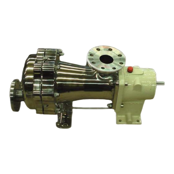
SLC24 - SLC36
(manufactured from 2009 to 2010)
Z.I. La Plaine des Isles - F 89000 AUXERRE - FRANCE
Tel. : +33 (0)3.86.49.86.30 - Fax : +33 (0)3.86.49.87.17
contact@mouvex.com - www.mouvex.com
PUMPS
INSTRUCTIONS 1004-C00 e
Section
1004
Effective
September 2009
Replaces
June 2009
Original instructions
INSTALLATION
OPERATION
MAINTENANCE
Your distributor :
Advertisement
Table of Contents

Related Manuals for Dover Mouvex SLC24


Summary of Contents for Dover Mouvex SLC24
- Page 1 INSTRUCTIONS 1004-C00 e Section 1004 Effective September 2009 Replaces June 2009 Original instructions SLC24 - SLC36 PUMPS (manufactured from 2009 to 2010) INSTALLATION OPERATION MAINTENANCE Your distributor : Z.I. La Plaine des Isles - F 89000 AUXERRE - FRANCE Tel. : +33 (0)3.86.49.86.30 - Fax : +33 (0)3.86.49.87.17 contact@mouvex.com - www.mouvex.com...
-
Page 2: Table Of Contents
ECCENTRIC PISTON PUMP MOUVEX PRINCIPLE SAFETY INSTRUCTIONS, STORAGE, INSTALLATION AND MAINTENANCE MODELS : SLC24 - SLC36 TECHNICAL CHARACTERISTICS - Maximum pump speed : 460 rpm - Maximum running temperature : Pump N° : * continuous ......100°C * washing/rinsing/sterilisation . -
Page 3: Overall Dimensions
1. OVERALL DIMENSIONS NT 1004-C00 09.09 SLC24 SLC36 e 3/21... - Page 4 1. OVERALL DIMENSIONS (continued) NT 1004-C00 09.09 SLC24 SLC36 e 4/23...
- Page 5 1. OVERALL DIMENSIONS (continued) NT 1004-C00 09.09 SLC24 SLC36 e 5/23...
- Page 6 1. OVERALL DIMENSIONS (continued) NT 1004-C00 09.09 SLC24 SLC36 e 6/23...
- Page 7 1. OVERALL DIMENSIONS (continued) NT 1004-C00 09.09 SLC24 SLC36 e 7/23...
-
Page 8: Installation
2. INSTALLATION POSSIBLE POSITIONS STANDARD SUCTION STANDARD DISCHARGE 2.3 PROTECTION OF THE PUMP INSTALLATION The SLC Series pump is a selfpriming volumetric PD pump. Therefore, the pump must not run on a circuit with a closed • For ease of maintenance, it is a good idea to place iso- valve. -
Page 9: Hoisting Devices
2. INSTALLATION (continued) 2.4 HOISTING DEVICES • Protection against excess pressure : The pump must be protected against excess pressure. Put a sling in the lifting ring of the transmission and ano- It can be delivered with a pressure switch to carry out ther under the pump cylinder. - Page 10 2. INSTALLATION (continued) If the unit is to be used in a food environment, support The 3 figures below show in detail the operation and the plates that allow the unit to be lifted for easier cleaning possible defects : are recommended.
-
Page 11: Utilisation
2. INSTALLATION (continued) WARNING 2.5.4 THERMIC MOTORS CAUTION IT IS IMPERATIVE THAT THE HYDRAULIC PRESSURE IS RELEASED BEFORE EACH MAINTENANCE OPERATION TO AVOID PERSONAL INJURY MATERIAL THE SURFACES CAN BE AT A TEMPE- Hazardous pressure DAMAGE RATURE LIABLE TO CAUSE INJURY can cause OR SEVERE DAMAGE. -
Page 12: Clean In Place (Cip) & Sterilisation In Place (Sip)
4. CLEAN IN PLACE (CIP) & STERILISATION IN PLACE (SIP) 4.1 GENERAL 4.3 PUMPS ARRANGED IN SERIES On-site cleaning (CIP) of an installation is undertaken by This type of assembly is preferred in all cases. It circulating various cleaning solutions through the equip- ensures optimal cleaning for the pump and makes use ment parts. -
Page 13: Pumps Arranged In Parallel
4. CLEAN IN PLACE (CIP) & STERILISATION IN PLACE (SIP) (continued) 4.4 PUMPS ARRANGED IN PARALLEL For applications where cleaning is easy and the differen- tial pressure of, the SLC Series pump is lower than 2 bar Max P 3 bar (29 psi) during this operation, assembly in parallel is authorised. -
Page 14: Successive Cycles
4. CLEAN IN PLACE (CIP) & STERILISATION IN PLACE (SIP)(continued) 4.5 SUCCESSIVE CYCLES 4.6 STERILISATION IN PLACE (SIP) Generally, the most efficient CIPs comprise 5 stages : The serie SLC pumps are perfectly adapted to all pro- 1. Pre-washing with clean water cesses using SIP (Sterilisation In Place) : pump stopped Water at room temperature. -
Page 15: Opening Of The Pump
6. OPENING OF THE PUMP WARNING WARNING DISCONNECTING THE FLUID OR PRES- TAKE ALL NECESSARY MEASURES TO SURE CONTAINMENT COMPONENTS RENDER ANY START-UP, EVEN ACCIDEN- DURING PUMP OPERATION CAN CAUSE TAL, OF THE PUMP DURING THE WORK SERIOUS PERSONAL INJURY, DEATH IMPOSSIBLE. -
Page 16: Assembly / Dismantling
6. OPENING OF THE PUMP (continued) 6.1 ASSEMBLY / DISMANTLING • Remove the seal 205. Before any dismantling, make sure that the pump has been drained and take the neces- sary measures to avoid starting-up. No start- up, even accidental, must be allowed. •... -
Page 17: Checking Of Parts
6. OPENING OF THE PUMP (continued) WARNING In order to benefit from this service, the parts must be within the minimum wear dimensions for Standard Exchange defined in the table below : BE CAREFUL WITH THE WEIGHT OF Piston Cylinder THE PARTS WHEN THEY ARE BEING REMOVED. -
Page 18: Assembly Of Cylinder/Piston
7. ASSEMBLY OF CYLINDER/PISTON WARNING • Check the state of the seals 205, 305, 306, 113 and repla- ce them if necessary. NOTICE : BE CAREFUL WITH THE WEIGHT OF THE PARTS WHEN THEY ARE BEING Seals are designed for use in normal conditions REMOVED. -
Page 19: Protection Of The Bellows
8. PROTECTION OF THE BELLOWS WARNING Under preventive maintenance (every 135 millions of cycles duty) or in case of damage of the bellows, we sug- gest transmission exchange program. BE CAREFUL WITH THE WEIGHT OF In this case : The transmission delivered is equipped with a THE PARTS WHEN THEY ARE BEING tubular foam protection. -
Page 20: Changing The Lip Seal
9. CHANGING THE LIP SEAL CAUTION • Re-mount the cover 607 after placing the seal 602, greasing the lips of the seals and greasing between the 2 seals 608. FOOD SYNTHETIC GREASE : THE PUMP LUBRICANT IS VERY SLIPPERY Compulsory reference because compatible AND MAY CAUSE SERIOUS INJURY. -
Page 21: Changing The Orientation Of The Ports
10. CHANGING THE ORIENTATION OF THE PORTS WARNING BE CAREFUL WITH THE WEIGHT OF THE PARTS WHEN THEY BEING REMOVED. The weight ot the parts can be dangerous and may provoke bodily injuries or material damages. 10.1 DISCHARGE PORT • Unscrew the 8 nuts 106 with the studs 105 and 107. •... -
Page 22: Draining Of Bearing
11. DRAINING OF BEARING CAUTION • Screw back the breather 715. THE PUMP LUBRICANT IS VERY SLIPPE- RY AND MAY CAUSE SERIOUS INJURY. ANY SPILLS MUST BE CLEANED UP. Slippery lubricant. Spills should be cleaned up. • Drain the transmission following the board below : •... -
Page 23: Options
12. OPTIONS 12.1 LIQUID DETECTOR 12.2 BELLOWS MONITORING SYSTEM The liquid detector works with single and double ply bel- The bellows monitoring system called (BMS) works only lows. It is install on the vent circuit (see § PROTECTION with double ply bellows. OF THE PUMP INSTALLATION).
Need help?
Do you have a question about the Mouvex SLC24 and is the answer not in the manual?
Questions and answers