Table of Contents
Advertisement
Quick Links
Advertisement
Table of Contents

Related Manuals for PCE Instruments PCE-TTC 30


Summary of Contents for PCE Instruments PCE-TTC 30
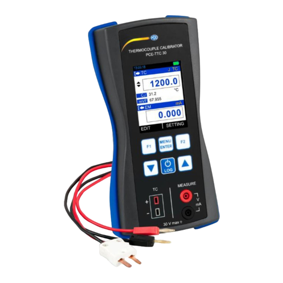
- Page 1 User Manual PCE-TTC 30 Temperature Sensor User manuals in various languages (français, italiano, español, português, nederlands, türk, polski, русский, 中文) can be found by using our product search on: www.pce-instruments.com Last change: 10 August 2018 v1.0 © PCE Instruments...
-
Page 2: Table Of Contents
Contents Safety notes ................... 1 PCE-TTC 30 Hardware Parts and Accessories ........2 Unpacking and Inspection ....................2 Operational Sections and Connections ................3 Power Options........................8 Battery ..........................8 Start Up and Basic Operations ............9 Power On or Off ....................... 9 User Interface ........................ -
Page 3: Safety Notes
We expressly point to our general guarantee terms which can be found in our general terms of business. If you have any questions please contact PCE Instruments. The contact details can be found at the end of this manual. © PCE Instruments... -
Page 4: Pce-Ttc 30 Hardware Parts And Accessories
PCE-TTC 30 Hardware Parts and Accessories Unpacking and Inspection At the factory each new PCE-TTC 30 passes a careful inspection. It should be free of scrapes and scratches and in proper operation order upon receipt. The receiver should, however, inspect the unit for any damage that may have occurred during transit. -
Page 5: Operational Sections And Connections
All sections and connections are presented in detail on the next pages. Note: Keep in mind that the next picture (as well as all pictures of the PCE-TTC 30 in this manual) has an example configuration of modules. The configuration of your PCE-TTC 30 may vary significantly from the one in the picture. - Page 6 Current Measurement In this mode, the PCE-TTC 30 does not provide any supply voltage. For proper measurement the external device should capable of providing the voltage supply. If the external device should not capable, an external Power Supply should be connected in series.
- Page 7 Read Power Current Measurement In this mode, the PCE-TTC 30 works as Loop Power Supply while at the same time measuring current. Voltage Measurement The PCE-TTC 30 is capable of voltage Measurement with two voltage measurement ranges. The following picture displays the connection for Voltage Measurement for different mode.
- Page 8 2.2.2 KeyPad The PCE-TTC 30 has six different keys. The key description is given below. This key has different functionalities in different menus. These are shown in the bottom left part of the display. This key has different functionalities in different menus.
- Page 9 • Supporting 262K colors 2.2.4 USB Connection The USB connection is located at the top of the PCE-TTC 30. It is a USB mini B-Type female • connector. • It can be used for PC communication and for charging the device.
-
Page 10: Power Options
(40%) and a short Timeout. The maximum operating time without recharging varies depending on the usage and brightness setting of the display light. Also the generated output and the usage of the 24 V transmitter supply affect the maximum operating time. © PCE Instruments... -
Page 11: Start Up And Basic Operations
Do not leave the PCE-TTC 30 without a Battery Pack or an Empty Battery for a long • time. The PCE-TTC 30 may lose its settings if it is left without a support voltage for an extended period. Start Up and Basic Operations Power On or Off To set the instrument power ON, press and release this button down until the display comes on. - Page 12 % is >= 50%, >= 20 and <20 respectively. Data Logging Enable Status Indicator Icon is visible if data logging is enabled and will flash when a data log is stored to the memory © PCE Instruments...
- Page 13 The function key bar at the bottom of the display is visible all the time. 2 function keys are available. The meaning of the function keys varies depending on the situation. A blank function key text means that the function is disabled at the moment. 3.2.3 Display Mode TC Mode © PCE Instruments...
- Page 14 CJC Temperature value if CJC mode is MANUAL. Reading The Reading unit is same as TC Unit. Shows the Addition Information according to TC Mode and Additional Additional Info selected in MENU → DISPLAY → TC terminal. Info © PCE Instruments...
- Page 15 Current Input mA(24V) mA Current (Read Power-24V) Input V Voltage Input The Measure Reading Display Mode EM Display Mode Actual Displays the Raw Input Value without any scaling Percentage Displays the Percentage Value Scaled Displays the Scaled Value © PCE Instruments...
- Page 16 Displays the Maximum-Minimum value found after a Max-Min measurement was started or Maximum-Minimum was reset. Displays the Cumulative Average value found after a Cumulative Average measurement was started or Cumulative Average was reset. © PCE Instruments...
- Page 17 Refer to EM Display Mode on previous pages. EM Input Type EM Reading HART Icon The Measure Reading Display Mode EM Display Mode “ “ Displays the Raw Input Value without any (Blank) scaling Displays the Percentage Value Displays the Scaled Value © PCE Instruments...
- Page 18 A ListBox list opens when you press the F1 key. Use the UP/DOWN key to scroll through the available options. Select one of the options with the ENTER key. Example: How to change of Input Type (I/P Type) from mA to V. This option is available in MENU → EM SETUP Page. © PCE Instruments...
- Page 19 & changing of sign is not allowed. But there are few EditBox, where these are allowed. Examples Scaled Low (0%) & High (100%) etc. The below figure shown the example how to change decimal point of the Input Scaled High (100%) Range. © PCE Instruments...
- Page 20 To change the sign of the value, shift to the sign digit and pressing UP or DOWN key will toggle the sign. © PCE Instruments...
- Page 21 In Radio Button Box the other option can be selected by pressing MENU/ENT key on that option. When pressing this key the new option will be selected and the other option will be disabled. Below an example is given, How to change TC Source Mode from STEP to RAMP. © PCE Instruments...
-
Page 22: Menu Layout
Contains Parameters related to different display mode for RUN DISPLAY page Contains Parameters related to Data Logging. LOGGING Contains Parameters related to Alarm & Alarm Set-Points. CJC Setting Contains Parameters related to General Settings of the device like display, Date/Time, Calibration, Reset, etc. SETTINGS © PCE Instruments... -
Page 23: Measure Page
Input High Range for Measure Input Range High Range: (100%) Input Range Low (0%)to Default Input High This parameter is enabled, if Main Display in MENU → DISPLAY → EM SETUP is set to Percentage or Scaled © PCE Instruments... - Page 24 This parameter is enabled, if Main Display in MENU → DISPLAY → EM SETUP is set to Scaled. Transfer Function for Scaling (Transfer Function) Available Options: Linear x^2 (x x^(1/2) (√x) This parameter is enabled, if Main Display in MENU → DISPLAY → EM SETUP is set to Scaled. © PCE Instruments...
-
Page 25: Source Page
This page appears when you select MENU TC SETUP. → → This page contains parameters related to Thermocouple like TC Mode Type, TC Type, Unit, TC Source Mode etc. The Description of the Parameters appear on this page is given below. © PCE Instruments... - Page 26 N TC -200.0 … 1300.0 °C -10 to 80 mV -10.000 … 80.000 mV 0.001 mV -10 to 250 mV -10.00 … 250.00 mV 0.01 mV TC Unit Unit Measure/Source Reading Unit Available Options: Celsius Fahrenheit Kelvin © PCE Instruments...
- Page 27 %, enter value in %. Step Manual Mode Selection CheckBox Manual (Output Type) Ticking this checkbox will enable Step Manual Mode and Un-ticking will enable Auto Step Mode. © PCE Instruments...
- Page 28 This parameter is enabled only for Auto Step Mode (Manual CheckBox is Un-Checked) Defines how many times the steps are repeated Repeat Repeat Counts Range: 1 … 9999 This parameter is enabled only for Auto Step Mode (Manual CheckBox is Un-Checked) © PCE Instruments...
- Page 29 STOP at any time in RUN Page. STEP Setting can be accessed directly by F2 key (SETTING). NOTE: While STEP is running STEP settings can’t be accessible and Source Page Parameter settings can’t be change. Stop STEP before changing any settings. © PCE Instruments...
- Page 30 Time to Increase from Low to High Level. Rise Time (s) Range: 1 … 9999 Time to wait at High (100%) level in second Hold@100%(s) This parameter is used for Repeat Format UP/DOWN or DOWN/UP. Range: 0 … 9999 © PCE Instruments...
- Page 31 Time to decrease from High to Low Level Fall Time (s) Range: 1 … 9999 How the Ramp should be done Repeat Format Available Options: DOWN UP/DOWN DOWN/UP Defines how many times the steps are repeated Repeat Repeat Counts Range: 1 … 9999 © PCE Instruments...
-
Page 32: Display Page
Page. What information to be shown in each RUN Display Mode can be defined by this page. In this page there is one RadioButtonBox. At a time one or two option can be selected. The possible combinations are given below. © PCE Instruments... - Page 33 Scaled Range and Transfer Function. These settings are available from MENU →EM SETUP. Order IIR Low Pass Filter for Input Reading Filter (sec) Filter is useful when a measurement signal contains unwanted noise. Range: 0.0 … 60.0 sec © PCE Instruments...
- Page 34 Display the Actual Thermocouple/mV Value Percentage Display the Percentage Value of Thermocouple/mV according to value set in 0% and 100%. Low Value in Temperature/mV for (0 … 100%) scaling. High Value in Temperature/mV for (0 … 100%) scaling. 100% © PCE Instruments...
- Page 35 Thermocouple Temperature/mV value without any Actual Value scaling. This option is available only if TC Display Mode is Percentage. Shows the Thermovoltage according to Temperature including CJ temperature mV. The mV which is sourced through TC Terminal. © PCE Instruments...
-
Page 36: Data Logging Page
This section gives examples of how to log Readings with time and date over a set time period or on a key press. Logged data is stored in a user defined file in internal memory. This Page appears when you select RUN →MENU →LOGGING. © PCE Instruments... - Page 37 Sampling Rate for Periodic Data Logging in seconds Sampling Rate(s) Range: 1 … 9999 This parameter is enabled only for Periodic Trigger. Total Logging Time in HH:MM:SS Format for Periodic Logging Logging Time (HH:MM:SS) This parameter is enabled only for Periodic Trigger. © PCE Instruments...
- Page 38 In Key Press Mode, If No of Samples reach its maximum limit that is 484, the next • sample will start from the first overwriting the memory. While Logging is running, entering into the LOGGING menu shows below page. • © PCE Instruments...
-
Page 39: Cjc Setting Page
Start this software just as any other Windows® software. All communication between the PC and PCE-TTC 30 is initiated from mCAL+.exe. More information on the software can be found in the separate software manual. CJC Setting Page This page appears when you select RUN →MENU →CJC Settings. -
Page 40: Setting Page
HART ii. Display iii. Date/Time iv. Calibration v. Battery Info vi. Set Password vii. Factory Reset viii. About Us Press F1 key to Enter into the settings of any option. Description of all settings is given below. © PCE Instruments... - Page 41 Standby Time in second after which display will turn Off. To turn the Time display off press any key. Range: 0 to 9999 sec Setting 0 will disable this feature. That means display will never turn off automatically. © PCE Instruments...
- Page 42 This source should be at least ten times accurate compared to the range of the instrument. Note: PCE Instruments can provide a calibration service that is traceable to international standards. We recommend that you return the instrument to the manufacturer or an approved service agent for calibration.
-
Page 43: Maintenance And Troubleshooting
PCE Instruments) Calibration Out Distortion in due to external noise connection • • (Solution: Check connection. If still out, contact PCE Instruments or Recalibrate Device in authorized calibration laboratory.) Battery Not Charging • Battery Connection Loose • Battery Dead Replacing the Battery ©... -
Page 44: Technical Specifications
2372°F 0.18°F 10 ... 80 mV 0.001 mV ± 0.02% of the displayed -10 ... 250 mV 0.01 mV value + 2μV ± 0.02% of reading + 0.02 Note: The specifications refer to the temperature standard ITS-90 © PCE Instruments... - Page 45 Battery operation: 0 ... 55°C / 32 ... 131°F, 30 ... 90% RH Main operation: 0 ... 45°C / 32 ... 113, 30 ... 90% RH Storage conditions -20 .. 60°C / -4 ... 140°F, 30 ... 90% rh non-condensing Heating time About 15 minutes © PCE Instruments...
-
Page 46: Warranty
For countries outside the EU, batteries and devices should be disposed of in accordance with your local waste regulations. If you have any questions, please contact PCE Instruments. © PCE Instruments... - Page 47 PCE Instruments contact information Germany France Spain PCE Deutschland GmbH PCE Instruments France EURL PCE Ibérica S.L. Im Langel 4 23, rue de Strasbourg Calle Mayor, 53 D-59872 Meschede 67250 SOULTZ-SOUS-FORETS 02500 Tobarra (Albacete) Deutschland France España Tel.: +49 (0) 2903 976 99 0 Téléphone: +33 (0) 972 3537 17...
Need help?
Do you have a question about the PCE-TTC 30 and is the answer not in the manual?
Questions and answers