
Related Manuals for Wilden Saniflo DUS


Summary of Contents for Wilden Saniflo DUS
- Page 1 DRUM UNLOADER SYSTEM E n g i n e e r i n g O p e r a t i o n & ™ Sanifl o Series M a i n t e n a n c e R e f i n e y o u r p r o c e s s Drum Unloader System...
-
Page 2: Table Of Contents
T A B L E O F C O N T E N T S SECTION 1 CAUTIONS—READ FIRST! ..........1 SECTION 2 DESIGNATION SYSTEM . -
Page 3: Cautions-Read First
Drain pump by turning it upside WARNING: It is important to follow the assembly instructions down and allowing any fl uid to fl ow into a suitable container. provided when building the Sanifl o™ DUS unit. Altering the WILDEN PUMP & ENGINEERING, LLC WIL-12070-E-03... -
Page 4: Designation System
K = 533 - 557 mm (21.0”-21.9”) FOLLOW PLATE MATERIAL PUMP TYPE L = 558 - 582 mm (22.0”-22.9”) S = STAINLESS STEEL S = SIMPLEX SINGLE ACTING D = DUPLEX DOUBLE ACTING SPECIALTY CODES 0070 Saniflo™ WILDEN PUMP & ENGINEERING, LLC WIL-12070-E-03... -
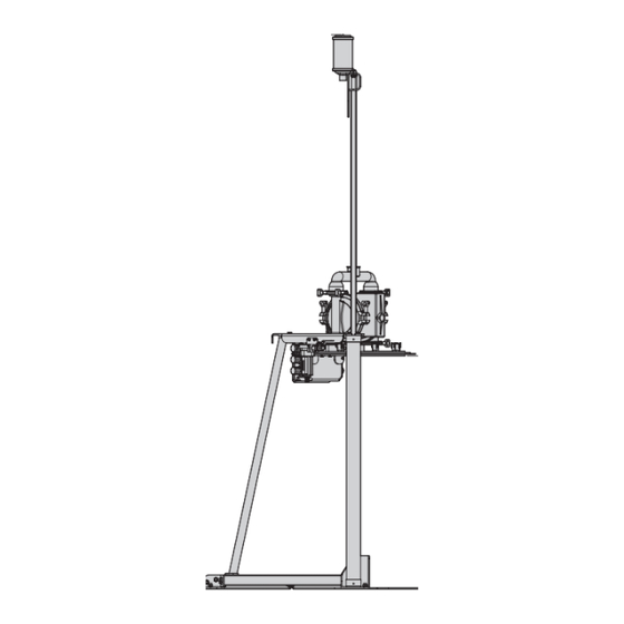
Page 5: Dimensional Drawings
D I M E N S I O N A L D R A W I N G DRU M UN LOA D E R SYST E M DIMENSIONS ITEM METRIC (mm) STANDARD (inch) 1143 45.0 1049 41.3 2667 105.0 1123 44.2 1567 61.7 1140 44.9 WILDEN PUMP & ENGINEERING, LLC WIL-12070-E-03... -
Page 6: Troubleshooting
1. Ensure that the correct gasket size is being used in accordance with the drum size. NOTE: The gaskets are NOT designed to completely seal against sides of drum. Under normal operating conditions, there will be some slight weeping of drum contents. WILDEN PUMP & ENGINEERING, LLC WIL-12070-E-03... - Page 7 Use beginning assembly of unit. the top support beam to raise the Leave fasteners hand tight. opposite end of the cylinders for proper alignment. WILDEN PUMP & ENGINEERING, LLC WIL-12070-E-03...
- Page 8 Use 12 mm bolts, nuts and lock shoulder then tighten. NOTE: Nut lock washer on the end of the rod washers and leave hand tight. should be between upper and lower and hand tighten. support bar holes. WILDEN PUMP & ENGINEERING, LLC WIL-12070-E-03...
- Page 9 140 mm (5.5”). Dimension C (mounting bolt holes from front of bottom base structure to back of structure) should be 763 mm (30.0”). WILDEN PUMP & ENGINEERING, LLC WIL-12070-E-03...
- Page 10 Install the air line from upper fasteners provided on the back of on the back of the control panel as left (ram down) port to the top the header plate. shown. connections on the two pneumatic cylinders. WILDEN PUMP & ENGINEERING, LLC WIL-12070-E-03...
- Page 11 Face the pump exhaust away from ram support bracket. the follower plate vent and align the bands to allow the free access to wiper seal bolt ring area. WILDEN PUMP & ENGINEERING, LLC WIL-12070-E-03...
- Page 12 NOTE: Be assembly to move up and down. sure to rotate the seams between the two gasket sets to avoid direct alignment. WILDEN PUMP & ENGINEERING, LLC WIL-12070-E-03...
- Page 13 Step 35 Step 36 Install user supplied discharge Thread discharge hose through hose on the pump using the support loop on the bottom of the necessary reducer, clamp band and ram support bar. o-rings. WILDEN PUMP & ENGINEERING, LLC WIL-12070-E-03...
-
Page 14: Operation
NOTE: Always set the regulator at cylinder connections are tight. the lowest possible air pressure for ity products. A 64 mm (2-1/2”) or the application. 76 mm (3”) hose is suggested for best performance. WILDEN PUMP & ENGINEERING, LLC WIL-12070-E-03... - Page 15 The gaskets are NOT designed to com- pletely seal against sides of drum. Under normal operating conditions, there will be some slight weeping of drum contents. WILDEN PUMP & ENGINEERING, LLC WIL-12070-E-03...
- Page 16 (off) ram plate to assist with removal. black knob to stop pump. NOTE: position. The ram control lever can remain in the down position even if the pump is not running. WILDEN PUMP & ENGINEERING, LLC WIL-12070-E-03...
- Page 17 (off) position once the ram fl ow coming through the ram vent. way for a new drum. plate has retracted to its full height. NOTE: Ensure the drum retainers are in place before starting this action. WILDEN PUMP & ENGINEERING, LLC WIL-12070-E-03...
-
Page 18: Cleaning
WILDEN PUMP & ENGINEERING, LLC WIL-12070-E-03... - Page 19 Refi ll the drum one more time and clear. allow pump to fl ush system until all fl uid is removed. WILDEN PUMP & ENGINEERING, LLC WIL-12070-E-03...
- Page 20 Step 13 each product different, and each application may have different cleaning requirements, it may be necessary to remove and disassemble the pump to ensure proper cleaning. WILDEN PUMP & ENGINEERING, LLC WIL-12070-E-03...
-
Page 21: A. Control Box
REGULATOR - 1/4" WITH 3/8" NPT PORTS DUS-5008 VALVE - RAM CYLINDER CONTROL - RED 3 POSITION LEVER DUS-5006 VALVE - RAM VENT CONTROL - GREEN PUSH/PULL BUTTON DUS-5009 VALVE - PUMP CONTROL - BLACK PUSH/PULL BUTTON DUS-5010 WILDEN PUMP & ENGINEERING, LLC WIL-12070-E-03... -
Page 22: Hoses
CONTROL BOX REAR SUPPLY PUMP Black Green CAUTION: Prior to operating the DUS unit, ensure that the air hoses are connected and secured properly. Yellow CAUTION: Always wear safety glasses when operating the DUS unit. WILDEN PUMP & ENGINEERING, LLC WIL-12070-E-03... - Page 23 E X P L O D E D V I E W A N D P A R T S L I S T I N G DRUM UNLOADER SYSTEM E X P L O D E D V I E W WILDEN PUMP & ENGINEERING, LLC WIL-12070-E-03...
- Page 24 M6X1X30 Hx Bolt 18.8 Stainless Steel DUS-6010 M6 Lock Washer 18.8 Stainless Steel (not shown) DUS-6008 M6X1.00 Hx Nut 18.8 Stainless Steel DUS-6009 Barrel Centering device; 304 SS DUS-2009 M12X1.75X30 mm Hx Bolt 18.8 Stainless Steel DUS-6004 WILDEN PUMP & ENGINEERING, LLC WIL-12070-E-03...
- Page 25 WILDEN PUMP & ENGINEERING, LLC WIL-12070-E-03...
- Page 26 Since the use of Wilden pumps and parts is beyond our control, we cannot guarantee the suitability of any pump or part for a particular application and Wilden Pump and Engineering, LLC shall not be liable for any consequential damage or expense arising from the use or misuse of its products on any application.
Need help?
Do you have a question about the Saniflo DUS and is the answer not in the manual?
Questions and answers