
Subscribe to Our Youtube Channel
Related Manuals for BONFIGLIOLI BX Series


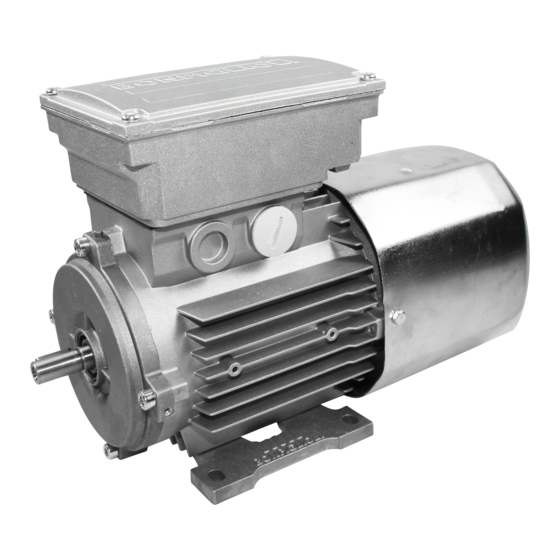
Summary of Contents for BONFIGLIOLI BX Series
- Page 1 BN-BE-BX-M-ME-MX series Installation, Operation and Maintenance Manual USER MANUAL...
-
Page 3: Table Of Contents
Read carefully Electrical hazard Revisions Refer to page 32 for the catalogue revision index. Visit www.bonfiglioli.com to search for catalogues with up-to-date revisions. 1 / 32 IOM BX-BE-BN-MX-ME-M_eng - Translation of original instructions in Italian - Rev 02_0 - 30/09/16... -
Page 4: Field Of Application
FIELD OF APPLICATION The following instructions apply to the three-phase asynchronous electric motors manufactured by BONFIGLIOLI RIDUTTORI S.p.A., series: - BX, BE, BN - MX, ME, M in their standard version, with or without brake. Special versions as described in the catalogues and/or in offers, or special applications (for example, power supply from inverter) will require additional information. - Page 5 Upon receipt of the motor, check that it was not damaged during transportation; if damage is noted, inform the carrier immediately. In addition, check that the characteristics stated on the plate conform to those ordered and confirmed by BONFIGLIOLI RIDUTTORI S.p.A. Transport and handling Cartons containing more than one motor are usually attached to wooden boards to facilitate handling by forklifts or transpallets.
- Page 6 Motors may be handled individually by lifting them with belts or chains (if required due to weight). Motors of frame sizes BX 100 / MX3, BE 100 / ME3, BN 100 / M3, and larger, are provided with an eyebolt / lifting point for lifting purposes. The eyebolts / lifting points are suitable for lifting the motor only.
- Page 7 Make sure that the motor is well-ventilated, that there is nothing to obstruct the free circulation of air, and that no situation will arise that could block the regular heat dissipation. The installation must also allow the performance of ordinary maintenance on the motor and, if sup- plied, of the brake.
-
Page 8: Wiring
WIRING Norms applicable to all motors Use cables with suitable section for the rated current and for installation conditions, avoiding exces- sive heating and/or voltage drops. Connection at the terminal board must be performed according to the diagrams shown in chart below or according to the instructions supplied in the terminal box, using the appropriate plates, nuts and washers. - Page 9 Ventilation Motors are cooled through outer air blow (IC 411 according to CEI EN 60034-6) and are equipped with a plastic radial fan, which operates in both directions. Ensure that fan cover is installed at a suitable distance from the closest wall so to allow air circulation and servicing of motor and brake, if fitted.
- Page 10 Fan terminals are wired in the motor terminal box V a.c. ± 10% P [W] I [A] BN 71 0.12 BN 80 1 ~ 230 0.12 BN 90 — 0.30 50 / 60 BN 100 0.12 / 0.09 BN 112 —...
- Page 11 Scheme (A) - Brake power supply from motor terminals and a.c. line disconnection. Delayed stop time t2 and function of motor time constants. Mandatory when soft-start/stops are required. Scheme (B) - Separate supply of brake coil and a.c. line disconnect. Regular stopping time, inde- pendent on time constants of motor.
-
Page 12: Start-Up
Switch-pole motors, nine pin motors (motors with voltage in ratio 2) and, at request, single-pole mo- tors with separate power supply are equipped with an auxiliary terminal board with 6 terminals for brake connection. In this version, motors feature a larger terminal box. See diagram: Brake Auxiliary terminal board... -
Page 13: Maintenance
MAINTENANCE Before any intervention, the motor, auxiliary circuits and/or accessories must be disconnected from the mains. In particular: - check disconnection from the electrical mains, - provide suitable protections from exposed live parts, - duble check that accidental restarts are not possible under any circumstances. It is recommended that periodical checks of motor operating conditions are scheduled as a routine maintenance practice. - Page 14 Check the air gap periodically and re-adjust it if dimension T is found exceeding the min/max values indicated in diagram. Particularly, brake may become noisier if gap is wider than the max value. In extreme cases releasing of the brake might also be affected. If the brake disengagement device is fitted, too wide a gap may lead the braking torque to drop significantly as a consequence of the reduced play in the release mechanism.
- Page 15 Brake torque setting on motors with a.c. brake (FA) Brake torque can be adjusted steplessly by changing the preload of springs (3). WARNING: For safety reasons, brake torque will not be set lower than 30% of rated value, even at springs fully unloaded.
- Page 16 Brake torque setting on motors with a.c. brake (BA) Loosen locking nut (2). Through nut (1) adjust the air gap and restore distance “T” to its minimum value, as listed in the chart Repeat the operation symmetrically on each stud bolt holding the brake. When setting is complete tighten nuts (1) and (2) on each stud bolt.
-
Page 17: Disassembly, Recycling Or Disposal
* = concerning hazardous components - hazardous components are not present in Bonfiglioli electric motors. NOTE: The above classification is referred to Bonfiglioli electric motors as per their factory initial con- ditions. Bonfiglioli is not responsible for any particular or inappropriate usage or modifications applied to the electric motors, which might require a different EWC classification. -
Page 18: Spare Parts
SPARE PARTS M05 FA 16 / 32 IOM BX-BE-BN-MX-ME-M_eng - Translation of original instructions in Italian - Rev 02_0 - 30/09/16... - Page 19 M05 FD 6250 (1220) 6234 1390 6444 1320 1360 (1240) 1328 (1200) (1370) (1230) 1180 1150 (6290) 6300 (6020) 1030 (6080) (6310) 1300 (6320) (1325) 1080 1290 1310 1010 (6030) (6050) 6440 1030 ref. Description ref. Description 1 Motor fl ange 1080 Shield for brake motor 1010 Stator 1290 Spacer ring...
- Page 20 M1 ... M4 ME2 ... ME4 MX2 ... MX4 M/ME M_ FD ME_ FD MX_ FD 1328 (1220) 6234 6250 (1230) 1080 M/ME 1310 (1240) 1320 1360 1180 1390 (1200) 1340 (6020) 1150 6385 (6290) 1030 (6300) 1030 (6080) (6310) (1325) (6320) 1300...
- Page 21 M1 ... M4 ME2 ... ME4 MX2 ... MX4 M_ FA ME_ FA MX_ FA M/ME ref. Description ref. Description 1 Motor fl ange 1080 Shield for brake motor 1010 Stator 1290 Spacer ring M_ FD 1030 Rotor 1310 Brake disc M_ FA 1100 Tie-rods 1320 Brake springs...
- Page 22 M5 FD ME5 FD MX5 FD 20 / 32 IOM BX-BE-BN-MX-ME-M_eng - Translation of original instructions in Italian - Rev 02_0 - 30/09/16...
- Page 23 M5 FA ME5 FA MX5 FA ref. Description ref. Description 1 Motor fl ange 1070 Rear shield M5 / ME5 1010 Stator KSA (6080) V-ring 1030 Rotor 1080 Shield for brake motor 1150 Fan 1310 Brake disc M5 FD 1180 Fan cowl 1320 Brake springs M5 FA (1200) Terminal box...
- Page 24 BN 63 ref. Description ref. Description 1010 Stator winding complete 6250 Terminal board 1030 Rotor shaft 6440 Flange bolt 1050 Mounting fl ange (IM B5/IM B14) 6444 NDE shield bolt 1070 Rear shield (6020) Bearing 1150 Fan (6030) Bearing 1180 Fan cover (6050) Compensation ring (6060) Key (1200) Terminal box lid...
- Page 25 BX 80 ... BX 132 BN 71 ... BN 160MR BE 80 ... BE 132 ref. Description ref. Description 1010 Stator winding complete 6234 Blank plug 1030 Rotor shaft 6250 Terminal board 1050 Mounting fl ange (B5/B14) (6020) Bearing 1070 Rear shield (6030) Bearing 1100 Tie-rods (6050) Compensation ring...
- Page 26 BX 160 , BX 180 BN 160M ... BN 200 BE 160 , BE 180 ref. Description ref. Description 1010 Stator winding complete 6234 Blank plug 1030 Rotor shaft 6250 Terminal board 1050 Mounting fl ange (IM B5) 6440 DE fl ange bolts 1070 Rear shield 6448 NDE shield bolts 1150 Fan...
- Page 27 BN 63 FD ref. Description ref. Description 1010 Stator winding complete 1328 Stainless steel disc (IP55) 1030 Rotor shaft 1360 Hand release lever 1050 Mounting fl ange (B5/B14) (1370) Grommet (IP55) (6080) V-ring (IP55) 1080 Rear shield 1150 Fan 1390 ac/dc rectifi er 1180 Fan cover (6020) Bearing (1200) Terminal box...
- Page 28 BN 71 FD ... BN 160MR FD BE 80 FD ... BE 132 FD BX 80 FD ... BX 132 FD ref. Description ref. Description 1010 Stator winding complete (1325) Brake hub 1030 Rotor shaft (6290) Key (brake hub) 1050 Mounting fl ange (B5/B14) (6300) Circlip 1080 Rear shield 1328 Stainless steel disc (IP55)
- Page 29 BN 160 FD ... BN 200L FD BE 160 FD , BE 180 FD BX 160 FD , BX 180 FD ref. Description ref. Description 1010 Stator winding complete 1328 Stainless steel disc (IP55) 1030 Rotor shaft 1360 Hand release lever 1050 Mounting fl ange (IM B5) (1370) Grommet (IP55) 1080 Rear shield (NDE)
- Page 30 BN 63 FA ref. Description ref. Description 1010 Stator winding complete 1328 Stainless steel disc (IP55) 1030 Rotor shaft 1350 a.c. brake type FA 1050 Mounting fl ange (B5/B14) (1370) Grommet (IP55) 1080 Rear shield (6080) V-ring (IP55) 1150 Fan 1380 Hand release lever 1180 Fan cover (6020) Bearing...
- Page 31 BN 71 FA ... BN 160MR FA BE 80 FA ... BE 132 FA BX 80 FA ... BX 132 FA ref. Description ref. Description 1350 a.c. brake type FA 1010 Stator winding complete 1030 Rotor shaft (1370) Brake seal kit (IP55) 1050 Mounting fl ange (B5/B14) (6080) V-ring (IP55) 1080 Rear shield...
-
Page 32: Iom Bx-Be-Bn-Mx-Me-M_Eng - Translation Of Original Instructions In Italian - Rev 02_0 - 30/09/16
BN 160 FA ... BN 180M FA BE 160 FA , BE 180 FA BX 160 FA , BX 180 FA ref. Description ref. Description 1350 a.c. brake type FA 1010 Stator winding complete 1030 Rotor shaft (1370) Brake seal kit (IP55) 1050 Mounting fl ange (IM B5) (6080) V-ring (IP55) 1080 Rear shield... - Page 33 BN 63 BA ... BN 132 BA ref. Description ref. Description 1010 Stator winding complete 1312 Armature plate 1030 Rotor shaft 1315 a.c. brake type BA 1050 Mounting fl ange (B5/B14) 1460 Brake release 1080 Rear shield (6020) Bearing 1100 Tie rods (6030) Bearing 1110 Fan cowling (6050) Compensation ring...
- Page 34 INDEX OF REVISIONS (R) BR_IOM_BX-BE-BN-MX-ME-M_STD_ENG_R02_0 Description … Removed information on brakes type AFD … Added information on BX, MX motors Added new chapter "Disassembly, recycling or disposal" This publication supersedes and replaces any previous edition and revision. We reserve the right to implement modifications without notice.
- Page 36 Our team creates, distributes and services world- class power transmission & drive solutions to keep the world in motion. HEADQUARTERS Bonfiglioli Riduttori S.p.A. Via Giovanni XXIII, 7/A 40012 Lippo di Calderara di Reno Bologna (Italy) tel: +39 051 647 3111 fax: +39 051 647 3126 bonfiglioli@bonfiglioli.com...
Need help?
Do you have a question about the BX Series and is the answer not in the manual?
Questions and answers