VIGO VG06041 Installation Manual
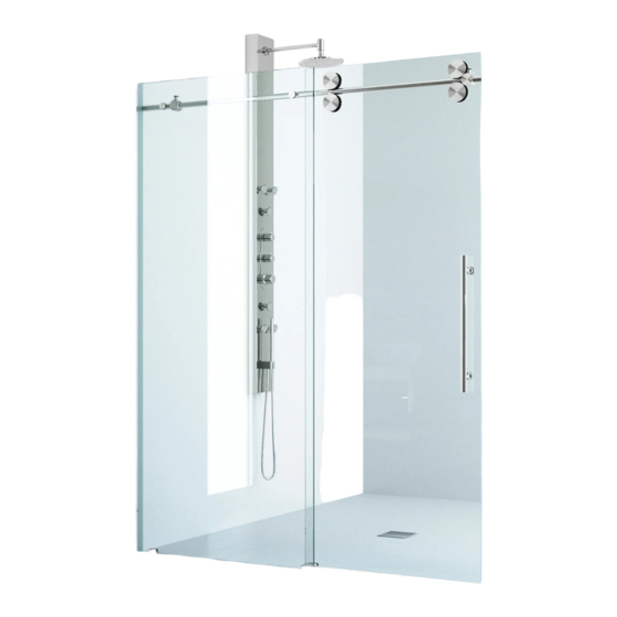
Shower enclosure
Hide thumbs
Also See for VG06041:
- Installation manual (17 pages) ,
- Installation manual (11 pages) ,
- Manuallines for installation (42 pages)
Table of Contents
Advertisement
VIGO INDUSTRIES INSTALLATION GUIDE FOR
SHOWER ENCLOSURE (MODEL VG06041)
!
SAFETY PRECAUTIONS
This Installation Guide uses the following symbols to indicate important information.
Always observe the instructions indicated by these symbols.
!
WARNING
Instructions that, if ignored, could result in death or serious personal injury caused by
incorrect handling or installation of the product. These instructions must be observed for
safe installation.
!
CAUTION
The instructions for the following unit is based off of the Vigo brand shower base. The
instructions can not be provided for any other installation other than that of the Vigo brand.
The warranty will be voided if the following was not performed properly.
IMPORTANT
Maintenance and other important non-personal injury and non-material damage instructions
or statements that should be observed.
It is highly advised to dry fit the unit prior to any installation.
*VIGO reserves the right to modify/update all hardware and glass components based on
bettering the product for the end user's experience. If you have any questions contact VIGO
Tech Support at 1-866-591-7792.
REV 1 - 4/6/18
1
Advertisement
Table of Contents

Related Manuals for VIGO VG06041


Summary of Contents for VIGO VG06041
- Page 1 CAUTION The instructions for the following unit is based off of the Vigo brand shower base. The instructions can not be provided for any other installation other than that of the Vigo brand. The warranty will be voided if the following was not performed properly.
- Page 2 MODEL VG06041 ELAN INSTALLATION INSTRUCTIONS FOR SHOWER DOOR PLEASE READ INSTRUCTIONS BEFORE PROCEEDING Parts List 1. Wall mount bracket (2pc) 11. Structural rail (1pc) 2. Fixed panel holders (2pc) 12. Door and fixed panel seal strip (2pc) 3. Rollers (4pc) 13.
- Page 3 31 1/2" A, B & C DIMENSIONS WERE MEASURED AFTER SHOWER ENCLOSURE WAS COMPLETELY INSTALLED Product lines may change, contact your Vigo representative at 1-866-591-7792 or visit our website at www.vigoindustries.com for the most up to date product line information.
- Page 4 Compare items on your invoice with what you have received. Carefully review the Parts List on page 2. If any items are missing, please call Vigo Industries at 1-866-591-7792. Please check our website at www.vigoindustries.com for additional information or instructional videos.
- Page 5 Ensure that there is sufficient structural support behind the shower wall to hold the weight of the shower door. If there is insufficient enough support, then reinforce the shower walls with wooden studs prior to shower door installation. [SEE FIG. 1] STUDS FIG.1 LEFT DOOR INSTALLATION RIGHT DOOR INSTALLATION MODEL VG06041...
- Page 6 4. Measure *70 7/16" for all shower doors or 62 3/8" for tub doors from the floor or curb of base. Mark this location. This will be the height of your wall mount bracket assembly (#1). MODEL VG06041...
- Page 7 Attach seal strip (#12) to the fixed panel on the side that sits against the wall. Start at the bottom and work your way up, using the heel of your hand to firmly press the seal strip WALL SIDE onto the glass. MODEL VG06041...
- Page 8 Mark the (#5) INSIDE OF THE SHOWER circumference location of the wall mount brackets (#1) on the wall. Mark the fixed panel bottom clip (#7) location and bottom door guide (#8) on the floor. MODEL VG06041...
- Page 9 Find the center of the marked circumference on the wall. Mark holes on the wall for the mounting screws. Drill holes and place plastic Preferred anchors (#17) inside them. method of installation negates anchors and has the installation going right into studs. MODEL VG06041...
- Page 10 (not provided). Epoxy should only be used on the fixed panel bottom clip and the bottom door guide. Proceed to Step 6 if this is your style of installation. MODEL VG06041...
- Page 11 BODY Place the fixed panel with the structural rail assembly in its proper position and thread PLATE the bracket body to the plates. BRACKET BODY Tighten the hex screws on the brackets with the hex key (supplied). SCREW MODEL VG06041...
- Page 12 Use the provided allen key to unscrew the adjustment screw and dismantle OUTSIDE OF the roller. Place the screw through THE SHOWER door panel top holes and attach the two top rollers onto the door panel (#5). ROLLER HEIGHT ADJUSTMENT SCREW MODEL VG06041...
- Page 13 Out of Square Openings . Once the rollers are properly adjusted and the door sits flush against the wall in the closed position, the adjustment will be complete. Fully tighten the adjustment screws and re-install the roller caps. MODEL VG06041...
- Page 14 Verify that the bottom of the door rests in the back notch of the bottom door guide (#8). Screw the two bottom rollers (#3) to the door panel as illustrated in step C2. MODEL VG06041...
- Page 15 (#8). Note that the end of the threshold should go halfway inside the bottom door guide and rest against the fixed panel (#4). If the threshold is too long, cut it with the hacksaw until it fits the opening. MODEL VG06041...
- Page 16 Remove any excess silicone from the threshold. INSTALLING THE HANDLE Unscrew the handle holders from the handle assembly (#6). Place the handle to the position on the door. Place plastic washers (supplied) on each side of the door. MODEL VG06041...
- Page 17 Attach the seal strip (#13) to the door and the fixed panel, respectively. Start at the bottom and work your way up, using the heel of your hand to firmly press the seal strip onto the glass. This end must look inside the shower MODEL VG06041...
- Page 18 (#13) to below this point Flange APPLYING THE SILICONE Apply clear silicone caulking along the wall and floor of the shower enclosure interior and along the fixed panel and threshold of the shower enclosure interior. MODEL VG06041...
- Page 19 In order to keep your shower enclosure in optimal working condition, Vigo recommends regularly inspecting your enclosure and tightening any hardware that may have loosened during use. This simple step will insure optimal results from your Vigo shower enclosure for many years to come.
- Page 20 ROLLER (3) 3/8" VARIANCE HEX SCREW FIG. 1 Lowest position Normal position Highest position FIG. 1A IMPORTANT NOTE: These adjustments are approximate. You may need to adjust the direction of the small hex hole to meet your needs. MODEL VG06041...
- Page 21 WALL OUT OF PLUMB WALL TILTS IN AT BOTTOM (EXAGGERATED FOR PURPOSE BOTTOM ANGLED WALL OF DEPICTION) ROLLER "A" ROLLER "B" WALL DIRECTION SMALL HEX HOLE SMALL HEX HOLE DIRECTION DIRECTION BOTTOM ANGLED ADJUST AS NEEDED FIG. 4 MODEL VG06041...
- Page 22 VIGO or an authorized VIGO dealer. VIGO warrants the seal strip components of the Product to be free from defects in workmanship and materials under normal use and service for a period of one (1) year from the initial date of purchase by the owner or end-user, contractor, or builder, from VIGO or an authorized VIGO dealer.
Need help?
Do you have a question about the VG06041 and is the answer not in the manual?
Questions and answers