
Related Manuals for Silca Twister 2


Summary of Contents for Silca Twister 2
- Page 1 Twister II Operating Manual Translation of original instructions D445476XA vers. 2.0...
- Page 2 © 2015 SILCA S.p.A. - Vittorio Veneto All rights reserved. No part of this publication may be reproduced or used in any form or by any means (photocopying, microfi lm or other) without the written permission of Silca S.p.A. Edition: July 2017 Printed in India by MINDA SILCA Engineering Ltd.
-
Page 3: Table Of Contents
INDEX GUIDE TO THE MANUAL ........................1 GENERAL INTRODUCTION ....................... 2 1 TRANSPORT ............................4 1.1 PACKING ...........................4 1.2 TRANSPORT ..........................4 1.3 UNPACKING ..........................4 1.4 HANDLING THE MACHINE ......................4 1.5 SAFETY ............................4 2 MACHINE DESCRIPTION ........................5 3 WORKING PARTS ..........................7 3.1 TECHNICAL DATA ........................8 3.2 ELECTRIC CIRCUIT ........................9 4 ACCESSORIES PROVIDED ......................10 5 MACHINE INSTALLATION AND PREPARATION ................11... -
Page 5: Guide To The Manual
LASER is the name given to the depths, positions and shapes special sidewinder milled keys Fig. 1 1) Head 5) Tip 2) Rim 6) Edge 3) Shoulder Stop 7) Cuts 4) Stem Copyright Silca S.p.A. 2017... -
Page 6: General Introduction
The work area is illuminated by a lamp which operates when the machine is switched on with the master switch. • Maintenance The operations to regulate, service, repair and clean the machine have been devised in the simplest and safest way possible. There is no danger of removable parts being re-placed wrongly or unsafely. Copyright Silca S.p.A. 2017... - Page 7 Twister II Operating manual - English • Machine identifi cation The TWISTER II key-cutting machine is provided with an identifi cation label which shows the serial number (Fig. Fig. 2 (*) see chap.9 DISPOSAL. Copyright Silca S.p.A. 2017...
-
Page 8: Transport
When the TWISTER II has been unpacked, place it directly on its workbench. This operation can be carried out by one person. ATTENTION: hold the base, and no other part, to lift and carry the machine. SAFETY • Protective shield A special transparent plastic shield prevents chippings from fl ying into the air. Copyright Silca S.p.A. 2017... -
Page 9: Machine Description
TWISTER II cuts the following types of keys: • DIMPLE KEYS (with fl at cuts) • LASER (SIDEWINDER) type keys • keys for FICHET DIMPLE KEYS LASER (SIDEWINDER) TYPE KEYS LASER NARROW-BLADE KEYS FOR FICHET (SIDEWINDER) TYPE KEYS (*) with Optional Fig. 4 Copyright Silca S.p.A. 2017... - Page 10 • lever (I) for vertical carriage (Z axis) • lever (C) X-Y axes Note: the letters in brackets refer to Fig. 6, page 7. The lever which guides movement along the X-Y axes is ergonomic and allows for precise, sensitive movements. Fig. 5 Copyright Silca S.p.A. 2017...
-
Page 11: Working Parts
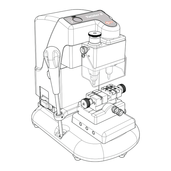
O - regulating knob spring system E1- right-hand jaw knob P - master switch G - protective shield Q - motor start switch H - clamp carriage locking knobs R - “Z” axis locking knob H1- clamp group locking knob Copyright Silca S.p.A. 2017... -
Page 12: Technical Data
24 Kg. Sound pressure: 74,7 dB(A) GRAPHICS ON THE TWISTER II MACHINE THE USE OF PROTECTIVE READ INSTRUCTIONS WARNING! BEFORE USE TOOL IN ROTATION GOGGLES IS REQUIRED WARNING! PRESENCE CUTTER ROTATION GROUND CONNECTION OF ELECTRIC POWER DIRECTION Copyright Silca S.p.A. 2017... -
Page 13: Electric Circuit
The main parts of the electrical and electronic circuit on the TWISTER II are listed below: 1) Machine plug 2) Fuses 3,15 Amp rapid (230V) - 8 Amp delayed (120V) 3) Master switch 4) Led 5) Motor start switch 6) Electric motor with collector 230/50 (120/50-60) Fig. 7 Copyright Silca S.p.A. 2017... -
Page 14: Accessories Provided
STEEL TIP STOP BAR 2 pcs. TRACER POINT for dimple keys FUSES (2 pcs) CUTTER 3,15 Amp - rapid (230V) for Laser (sidewinder) keys 8 Amp - delayed (120V) TRACER POINT for Laser (sidewinder) keys Copyright Silca S.p.A. 2017... -
Page 15: Machine Installation And Preparation
• master switch (P) • motor start switch (Q). • levers: lever (C) to move the clamp carriage lever (I) to move the vertical carriage Note: the letters in brackets refer to Fig. 6, page 7. Copyright Silca S.p.A. 2017... -
Page 16: Machine Regulation And Utilization
2) Place the cutting tool all the way into the right-hand sleeve and secure by tightening the grub screw (M1). Releasing the tools Unscrew the grub screw (M) and (M1) to remove the tracer point and cutting tool from the sleeves. Fig. 10 Copyright Silca S.p.A. 2017... -
Page 17: Calibration Of Cutter And Tracer
(Fig. 13). 6) Lock the bigger middle ring nut’s locking knob (H2). 7) Turn the upper ring nut (O) clockwise up until it is tight to cut laser (sidewinder) type keys. Fig. 11 Fig. 12 Fig. 13 Copyright Silca S.p.A. 2017... -
Page 18: Cutting Operations
2) Lock the key to be cut in the right hand clamp of the machine making sure that the key stop ispressed against the clamp. 3) Every time cutter or tracer point are changed, check machine calibration according to chap.6.2. 4) Cut the key according to chap.7.1 . Copyright Silca S.p.A. 2017... -
Page 19: Cutting Keys Without Key Stops
2) Lower the spindle and rest the tracer point on a cut part of the original key, cut the key and stop atthe beginning of the cut. • secure the spindle at this height by means of knob (R). • carry out the cuts using only the left-hand lever (C). Fig. 17 Copyright Silca S.p.A. 2017... -
Page 20: Cutting Narrow-Blade Laser (Sidewinder) Type Keys
Turn on switch (Q), lower the collet assembly and position on the beginning of the cut. • secure the spindle at this height by means of knob (R). • carry out the cuts using only lever (C). Fig. 19 Copyright Silca S.p.A. 2017... -
Page 21: Maintenance
5) Secure the motor by tightening the four socket head screws (Y2). 6) Replace the upper casing (Y), secure with the four screws (Y1) and replace knob (R). Fig. 20 Copyright Silca S.p.A. 2017... -
Page 22: Replacing The Lamp
It is advisable to check the fuses if the machine is not activated by turning on the master switch. Proceed as follows: 1) Turn off the master switch (P) and remove the power cord. 2) Remove the fuse board with the aid of a screwdriver. Fig. 22 Copyright Silca S.p.A. 2017... -
Page 23: Replacing The Jaws On Right-Hand Clamp
3) Fit the new jaw up against the right-hand side and align also from the front. 4) Tighten the 2 screws (B3) without exerting pressure. 5) Screw in the knob (E1). 6) Fully tighten the screws (B3). Fig. 25 Copyright Silca S.p.A. 2017... -
Page 24: Disposal
The sanctions currently provided for by law shall apply to users who dispose of products in unauthorised ways Copyright Silca S.p.A. 2017... -
Page 25: After-Sales Service
The limited warranty period for the TWISTER II key-cutting machine ensures free repairs or replacements of faulty parts within 24 months of purchase. All other service calls must be arranged by the customer with Silca or its Service Centres . - Page 26 European Union DIRECTIVE 2006/95/CE (Low Voltage) and with the IEC/EN 60204 – 1 : 2006 + Amd. 1 2009 Standards Claudio Tomasella of the Silca S.p.A. Research & Development Division is authorized to create a Technical File. General Manager Basic Production Center...
Need help?
Do you have a question about the Twister 2 and is the answer not in the manual?
Questions and answers