Table of Contents
Advertisement
Quick Links
Advertisement
Table of Contents

Related Manuals for Silca Optika


Summary of Contents for Silca Optika
- Page 1 Operating manual D433712XA vers.
- Page 2 This manual has been drawn up by SILCA S.p.A. All rights reserved. No part of this publication may be reproduced or used in any form or by any means (photocopying, microfilm or other) without the written permission of SILCA S.p.A. Edition: February 2017 Printed in Vittorio Veneto by SILCA S.p.A.
-
Page 3: Table Of Contents
Positioning ........................9 Description of work station .................... 9 USING OPTIKA ........................10 Optika’s software update .................... 10 Interface flow on the machine ..................10 Initial operations ......................10 Fitting or removing the key into or from the clamp ............11 5.4.1... - Page 4 6.4.7.4 TELECAMERA and LED ..................44 6.4.7.5 DISPLAY ........................44 6.4.7.6 KEYBOARD ......................44 6.4.8 UPDATING OPTIKA INTERNAL PROGRAM ............... 45 6.4.9 SERVICE MENU ......................45 MAINTENANCE ........................46 Clamp replacement ....................46 Clamp cleaning ......................47 Check machine gauging ..................... 47 Knob replacement (ESC/ENTER) ................47 DISPOSING OF MACHINE ......................
-
Page 5: Guide To Consultation
Operating manual - English GUIDE TO CONSULTATION This manual has been produced to serve as a guide for users of the OPTIKA device. Read it carefully; it is essential if you wish to operate your machine safely and efficiently. Consultation The contents of the manual are divided into sections relating to: Transport and handling ........................ -
Page 6: General
The device is powered by electricity through a 15 Vdc universal power supply unit, provided. Attention: as the device has no master switch, it remains live when connected. ATTENTION: if the power supply must be cut off, wait at least 10 seconds before re-connecting Optika to the mains. -
Page 7: Transport
Optika Operating manual - English TRANSPORT The OPTIKA device is easily transported and is not dangerous to handle. The device can be carried by one person, even when packed. Packing The OPTIKA device is packed in a strong cardboard box, the dimensions of which are shown in fig. 3 sufficiently robust to be used for storing the machine for long periods. -
Page 8: Accessories Provided
Operating manual - English Optika ACCESSORIES PROVIDED The tools provided by Silca are those necessary and sufficient for carrying out the operations involved. Power supply unit Serial cable Light shade device Power cable for bit and pump keys Setting template Z23 CD rom "Key Reader Program"... -
Page 9: Description Of Device
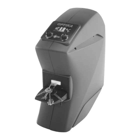
Operating manual - English DESCRIPTION OF DEVICE OPTIKA is a key-reading device that incorporates high quality performance and precision. Optika reads a profile and recognises most flat, bit and double bit keys, subject to their being included in the Silca database. flat keys... -
Page 10: Main Characteristics
Note: the Stand By function has been adopted to safeguard duration of the display. • DATABASE The database on the machine is a summary of all the profiles for keys produced by Silca and recognisable by the device (not the full Silca range). Technical Data DIMENSIONS: width: 190 mm - depth: 480 mm - height: 400 mm NET WEIGHT: 9Kg. -
Page 11: Main Operating Parts
Optika Operating manual - English Main operating parts Fig. 7 OPTIKA device Key clamp Clamp-opening lever Display ENTER Knob/push button ESC Knob/push button Illuminators Power supply socket Serial receptacle USB receptacle (slave) Double USB receptacle (master) Power supply unit Fig. 8... -
Page 12: Device Installation And Preparation
However, some checks and preparation for use have to be carried out by the operator. Separate Parts Power supply cable and power supply unit Connect OPTIKA to the power supply unit (M) and connect to the power source by means of the power supply cable (fig. 9). power supply cable Fig. -
Page 13: Positioning
Operating manual - English Positioning Place the OPTIKA device on the mat provided, on a solid horizontal worktop suitable for the weight of the machine (9 Kg). ATTENTION: position OPTIKA device away from sources of light (spotlights, lamps, etc..). ATTENTION: it is advisable to place the device in a clean dust-free environment. -
Page 14: Using Optika
Enlarging views of comparisons of profiles read with those in the Silca database. • Updating Optika internal program. Optika’s software update To update Optika’s software, refer to instructions in chapter ch. 6.4.8, page 45. Interface flow on the machine Optika comes with: a graphics display of 5 lines and 20 characters 2 knobs/push buttons that move the display pointer up/down, right/left;... -
Page 15: Fitting Or Removing The Key Into Or From The Clamp
If the key is one of a bunch, it can still be read, as long as the clamp functions and the key position are not affected. • Only keys can be fitted into the Optika device clamp (for maximum dimensions see fig. 5, page 6). Fitting Note: make sure the clamp (which can be opened and rotated) is well centred and not turned fully left or right (fig. -
Page 16: Key Insertion
(fig. 15). 2) With the clamp open, lift the key in it so that the glass plate is not scratched and remove the key. 3) Release the clamp opening lever. Fig. 15 Copyright Silca 2017... - Page 17 Optika Operating manual - English Fig. 16 Fig. 17 Fig. 18 Copyright Silca 2017...
-
Page 18: Fitting Of Shoulder Stop Key With Adapter (Code D737017Zb)
2) With the lever down fit the key with its stop up against the D737017ZB stop on the adapter (fig. 21). adapter for ATTENTION: the bit must be facing left. shoulder stop keys 3) Release the lever and proceed with the operation in question. Fig. 19 Fig. 20 Fig. 21 Copyright Silca 2017... -
Page 19: Instructions For Use
Silca database. • This function is used to detect the profile of a spare key (not Silca) when the Silca comparatives are not known, by finding the corresponding reference (if in the Silca database). -
Page 20: Key Positioning
- The bit must go past the illuminators. the illuminators. - A minimum of 10 mm. of stem must be - The bitting of single side keys must face left. inserted. - The key stem must be entirely surrounded by the light shade device. Copyright Silca 2017... -
Page 21: Step 1: Viewing The Cuts
If the top bar shown on the display is not a fine line, turn the clamp slightly to the right or left until it appears as required. • The better alignment, the better reading will be of stem or bit length. Copyright Silca 2017... -
Page 22: Step 2: Viewing The Profile
However, it is important that the outline of the profile is well defined; at ti- mes it is necessary to find a compromise between the thickness of the up- per alignment bar and the image of the profile. Copyright Silca 2017... - Page 23 Profile compatibility 1st group graduated scale Groups of keys found Identical keys (profile, stem, bit) Key thickness or stem diameter Bit length or stem length from stop to tip 2nd group Hook position Supplemental data Fig. 26 Copyright Silca 2017...
- Page 24 If the broad search produces no results the following display will appear: At this point the search has not been able to find any proper reference among Silca or User profiles. It is advised to save the profile as a User Profile if it is to be included in the Database as a reference for upcoming searches.
-
Page 25: Special Cases
With a cut key the profile is read properly and recognized only if the cuts have not touched or altered the part used for recognition. KEY-BLANK profile CUT key profile CUT key profile search result: OK search result: NEGATIVE Fig. 28 Copyright Silca 2017... - Page 26 3) remove the key and fit the light shade device. 4) STEP 2: fit the key again with the light shade device (fig. 30-B) and press ENTER. STEP 1: Viewing the CUTS adattatore oscuratore Fig. 29 STEP 2: Viewing the PROFILE light shade device Fig. 30 Copyright Silca 2017...
-
Page 27: Supplementary Search Data
3 - PROFILE INFO Press ENTER, a list will appear of references to spare key manufacturers different from the Silca reference blank (found by searching with Optika) and highlighted on the last line on the bottom of the display: Comparatives... - Page 28 Optika Press ENTER, a list will appear of alternative articles: Alternatives AB1X AB1BZ AB1Q AB1DA AB1 : SILCA 4 - SAVE PROFILE The following display will appear: Save read profile Name: Make: Hook: 1) Turn the ENTER knob to select the field into which the data will be entered.
-
Page 29: Possible Errors In The "Key Search" Function
If there is no result after a search by make, the possible condition is: • The key is a new original one not yet produced by Silca S.p.A. The profile of a loaded key can be saved by associating it to its manufacturer. -
Page 30: Key Matching
Note: as these keys are duplicates, make sure they are carefully cleaned (profile and cuts) (use the brush provided). Note: for more accurate cut comparisons, follow all the key fitting procedures in ch.5 and all the instructions in ch.6. Copyright Silca 2017... -
Page 31: Matching From "New Reading
There are 2 ways of using “Compare Cuts”. • Select "New Reading" when in Optika’s memory there is NOT a read key, useful for the comparison. • Select "Last Reading" when in Optika’s memory there is a read key, useful for the comparison. - Page 32 If not, the results of comparison will be negative or the following message will appear: To obtain a correct match rotate the key of 180°! COPY COPY ORIGINAL KEY Fig. 33 COPY COPY ORIGINAL KEY Fig. 34 Copyright Silca 2017...
- Page 33 13) Make sure the left-hand yellow bar should point upwards as much as possible. If not, follow the instructions in ch.6.1. 14) Confirm with ENTER, a few seconds later the display will show the matching result (Examples): Copyright Silca 2017...
- Page 34 Smiling face= indicates positive result of the profile comparison (*) Sad face= indicates negative result of the profile comparison (*) (*) Results referred to the parameters set in OPTIONS -> Search type (ch.6.4.5). • Turn the right-hand knob (ENTER) to select side 1 or side 2. Copyright Silca 2017...
- Page 35 Press ENTER, the display will show the profile: Smiling face= indicates positive result of the profile comparison (*) Sad face= indicates negative result of the profile comparison (*) (*) Results referred to the parameters set in OPTIONS -> Search type (ch.6.4.5). Copyright Silca 2017...
- Page 36 Operating manual - English Optika MATCHING TYPE FLAT KEYS Values table (0,01mm) spaces depths Standards set by Silca +/- 15 +/- 10 FINE Cannot be edited (0,004") (0,004") Standards set by Silca +/- 30 +/- 20 STANDARD Cannot be edited (0,008")
- Page 37 (0,0004 inch) 0.03:cuts on the key compared with the cuts on the original key are closer to the tip by 0,03 mm (0,0012 inch) • Turn the right-hand knob (ENTER) to select bit 1 or bit 2. Copyright Silca 2017...
- Page 38 Press ENTER, the display will show the profile: Smiling face= indicates positive result of the profile comparison (*) Sad face= indicates negative result of the profile comparison (*) (*) Results referred to the parameters set in OPTIONS -> Search type (ch.6.4.5). Copyright Silca 2017...
-
Page 39: Matching From "Last Reading
6.2.2 MATCHING FROM "LAST READING" Last Reading: in Optika’s memory there is always the last key read (regardless of whether the “Key Search” or "Key matching" functions have been used). Therefore, if with an “original” key the “Key Search” function had been used to find the corresponding reference, the copy made can be compared by using “Last Reading”. - Page 40 Among possible causes: no key is been actually read previously the reconstruction of the bitting previously read is not correct Repeat the comparison of the original and copy key as a “Comparison from new reading ”. Copyright Silca 2017...
-
Page 41: Key Copy
Key copy The Optika device is used to read then transmit the cuts of a bit key directly to the IDEA key-cutting machine without the aid of a personal computer. Optika can be used as an alternative to the optic reader on the IDEA key-cutting machine, considerably reducing reading times. -
Page 42: Transmission At The End Of A Search
Operation not possible with connected machine Appears if the key cutting machine connected to Optika is not the required one. Major error during transmission Appears if during transmission there is an interruption in the serial connection or an error in the transmission data. -
Page 43: Options
Press the ENTER knob to view the selection asterisk. Press ESC to go back to the previous menu; the language remains the one already in use. Note: to make the chosen language operative, disconnect the device and wait 10 seconds before starting up again. Copyright Silca 2017... -
Page 44: User Profiles
Delete profile? <AAA> Press the ESC knob to return to the previous menu without confirming deletion. • To delete profile: - turn the ENTER knob to select “Yes". - press the ENTER knob to confirm deletion. Copyright Silca 2017... -
Page 45: Keys In Stock
Standard Extended The possible settings (Fine - Standard - Extended) have been designed and defined by Silca to provide fine, medium or extended compatibility. According to the set search parameter the result will show a few or many key blanks. -
Page 46: Test Hardware
1) Fit the Z23 template as if it were a flat key, making sure that the special stop is facing downwards and butting against the illuminator (fig. 41). Fig. 41 2) Standard key alignment procedure. 3) After confirmation the following display will appear (examples with purely indicative values): Copyright Silca 2017... -
Page 47: Check Profile Area
0.030001 *dL: -8.350000 *dT: -2.150000 Example 1: satisfactory gauging Example 2: the asterisk shows that gauging is not satisfactory (values out of range). Contact Silca’s Technical Assistance Dept. 6.4.7.2 CHECK PROFILE AREA Note: this operation is necessary when the image is out of focus or faulty and must be carried out only on the advice of SILCA after-sales staff. -
Page 48: Check Cuts Area
Note: this operation is necessary when the image is out of focus or faulty and must be carried out only on the advice of SILCA after-sales staff. The operation is used to gauge the clamp illumination area (position of key). -
Page 49: Updating Optika Internal Program
ATTENTION: communication between a PC and the Optika USB (slave) will be available with a future software release. 6.4.9 SERVICE MENU Function protected by password. Access is granted to Silca personnel only or to centres authorized by Silca to carry out work on this type of device. Copyright Silca 2017... -
Page 50: Maintenance
Operating manual - English Optika MAINTENANCE Note: all internal tests and repairs on this device should be performed only at Silca or Authorised Centres. ATTENTION: for repairs or replacement of parts for maintenance, the ‘CE’ mark is guaranteed only if original spare parts provided by the manufacturer are used. -
Page 51: Clamp Cleaning
With device connected, fit the (Z23) template into the clamp (see ch.6.4.7.1, ch.6.4.7.2, and ch.6.4.7.3). Knob replacement (ESC/ENTER) 1) Unplug the power supply unit 2) Pull the knob upwards (simply pressed in). 3) Fit the new knob, paying attention to the shaped part of the pin. Fig. 43 Copyright Silca 2017... -
Page 52: Disposing Of Machine
The sanctions currently provided for by law shall apply to users who dispose of products in unauthorised ways. Copyright Silca 2017... -
Page 53: After-Sales Service
How to request service The guarantee attached to the OPTIKA device ensures free repairs or replacements of faulty parts within 24 months of purchase. All other service calls must be arranged by the customer with Silca or with a Silca authorized Service Centre. -
Page 55: Appendix 1 - Electric Diagrams
Operating manual - English OPTIKA Appendix 1 - ELECTRICAL DIAGRAMS The following pages contain the electrical diagrams for the OPTIKA device described in this manual. Copyright Silca 2017 Appendix - I... - Page 57 Fiche Entrées/Sorties Scheda Madre Presa alimentazione Mother Board Ficha Entradas/Salidas Power supply socket Mutterkarte Steckdose Speisegerät Carte mère Prise alimentation Ficha madre Toma de alimentación Scheda obiettivo Objective board Objektiv-Karte Fiche objectif Ficha objetivo Copyright Silca 2017 Appendix - III...
- Page 58 Unterer Illuminator Illuminateur inférieur Iluminador inferior Scheda uscita illuminatori Illuminators outlet board Illuminatoren Ausgang-Karte Fiche sortie illuminateurs Ficha salida iluminadores Scheda piano luminoso Bright plan board Karte leuchtender Plan Fiche étage lumineux Ficha plan luminoso IV - Appendix Copyright Silca 2017...
- Page 59 VITTORIO VENETO 04/01/2010 CE DECLARATION OF MACHINE COMPLIANCE SILCA S.p.A. - VIA PODGORA 20 ( Z.I.) 31029 VITTORIO VENETO (TV) - (ITALY) TEL. 0438 9136 - FAX. 0438 913800 Declares under its own responsibility that the Reader model OPTIKA complies with the requirements of the following European Directives:...
- Page 60 Phone: +39 0438 9136 Fax +39 0438 913800 E-mail: silca@silca.it www.silca.biz India United Kingdom MINDA SILCA Engineering Ltd. SILCA Ltd. Plot no.37, Toy City, Unit 6 Lloyds Court - Manor Royal GREATER NOIDA (U.P.) - 201308 CRAWLEY RH10 9QU Phone: +91 9871397630/31...
Need help?
Do you have a question about the Optika and is the answer not in the manual?
Questions and answers