Table of Contents
Advertisement
Quick Links
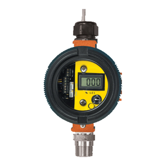
Combustible Gas Transmitter
Home Office
Analytical Technology, Inc.
6 Iron Bridge Drive
Collegeville, PA 19426
Phone: 800-959-0299
610-917-0991
Fax:
610-917-0992
Email: sales@analyticaltechnology.com
Web: www.Analyticaltechnology.com
Fax: 610-917-0992
O & M Manual
C12-17
Fax:
+ 44 (0)1457-874-468
European Office
ATI (UK) Limited
Unit 1 & 2 Gatehead Business Park
Delph New Road, Delph
Saddleworth OL3 5DE
Phone: +44 (0)1457-873-318
Fax:
+ 44 (0)1457-874-468
Email: sales@atiuk.com
Advertisement
Table of Contents

Subscribe to Our Youtube Channel
Related Manuals for ATI Technologies C12-17


Summary of Contents for ATI Technologies C12-17
- Page 1 O & M Manual C12-17 Combustible Gas Transmitter Home Office European Office Analytical Technology, Inc. ATI (UK) Limited 6 Iron Bridge Drive Unit 1 & 2 Gatehead Business Park Collegeville, PA 19426 Delph New Road, Delph Phone: 800-959-0299 Saddleworth OL3 5DE...
-
Page 2: Table Of Contents
DISPLAY & RELAY OPTION......................... 16 ALARM ADJUSTMENT ......................18 TROUBLE FUNCTION ......................18 C12-17 TRANSMITTER W/O DISPLAY SPARE PARTS LIST ............19 C12-17 TRANSMITTER WITH DISPLAY SPARE PARTS LIST ............20 TABLE OF FIGURES FIGURE 1 - TYPICAL SYSTEM DIAGRAM (ATI-0145) ................4 FIGURE 2 - COMBUSTIBLE GAS SENSOR/TRANSMITTER DIMENSIONS (ATI-046) ...... -
Page 3: Introduction
C12-17 transmitters are available in two versions, one containing an integral display and single alarm relay, and a second that is a simple “blind transmitter”... -
Page 4: Specifications
C12-17 Combustible Gas Transmitter SPECIFICATIONS Range: 0-100% LEL (Lower Explosive Limit) Standard 0-50% LEL Optional Response Time (T90) 10 Seconds Sensitivity: 1% LEL Zero Drift: < 2%/Month Power: 10-28 VDC, 24 VDC at 100mA nominal Output: 4-20 mA DC, 200 ohms maximum load at 12 VDC... -
Page 5: Installation
Series C12-17 transmitters require connection to a DC power supply and connection of the 4-20 mA output to a receiving device such as a computer, recorder, or data logger. A 3-conductor cable may be used for this purpose and is made at the terminals marked TB1 on Figure 3. -
Page 6: Sensor Location
C12-17 Combustible Gas Transmitter SENSOR LOCATION Combustible gas sensors are used to detect a variety of gases or vapors. The proper sensor location will depend on what type of gas is expected. For gases that are lighter than air, such as methane, sensors should be located near the ceiling. -
Page 7: Electrical Connections - Transmitter
C12-17 Combustible Gas Transmitter ELECTRICAL CONNECTIONS - TRANSMITTER External connections to the C12-17 transmitter can be made using 3 conductor cable. A 3- conductor cable uses a single conductor for the common of both the power supply and the output signal. -
Page 8: Electrical Connections - Sensor
C12-17 Combustible Gas Transmitter ELECTRICAL CONNECTIONS - SENSOR Standard transmitters supplied with the sensor close coupled to the transmitter enclosure are factory wired as shown below. However, sensors can be supplied with up to 25 feet of cable for remote mounting. -
Page 9: Dual Condulet System
C12-17 Combustible Gas Transmitter DUAL CONDULET SYSTEM For some indoor applications, it is more convenient to mount the sensor toward the ceiling of the room while keeping the transmitter electronics down at a convenient elevation for making calibration adjustments. ATI's dual condulet system is designed for this purpose, and the interconnecting wiring is shown below. -
Page 10: Operation
C12-17 Combustible Gas Transmitter OPERATION Once installation is complete, the C12-17 combustible gas transmitter is ready for operation. After verifying that electrical connections have been made properly, put the transmitter into operation by simply applying DC power. As soon as power is applied, the unit will begin to stabilize. Once stabilized, alarm system inhibit can be turned off, and the system will be in normal operation. -
Page 11: Transmitter Zero
C12-17 Combustible Gas Transmitter LEL Transmitter Figure 7 - Sensor/Transmitter Connectors, Controls and Test Points (ATI-0143) TRANSMITTER ZERO The transmitter zero is adjusted with the sensor exposed to air that contains no combustible gas. Generally, the easiest method of zeroing the transmitter is to make the adjustment when you know that the area is free of combustibles. -
Page 12: Transmitter Span
TRANSMITTER FAULT INDICATION The C12-17 combustible gas transmitter is designed to detect certain fault conditions in the sensor and transmitter and to indicate the fault conditions by driving the 4-20 mA output to below 2 mA. -
Page 13: Calibration For Other Combustible Gases
C12-17 Combustible Gas Transmitter CALIBRATION FOR OTHER COMBUSTIBLE GASES As previously mentioned, a combustible gas sensor has a slightly different response to each combustible gas or vapor. In addition, the LEL (Lower Explosive Limit) represents different percent concentrations for different gases. For instance, the LEL for methane is 5% by volume while the LEL for butane is 1.9% by volume. -
Page 14: Sensor Response Test
C12-17 Combustible Gas Transmitter SENSOR RESPONSE TEST While zero and span adjustments are required only periodically, gas sensors should be checked regularly for proper response. The response check can be done quickly by simply aiming the outlet tube from the span gas cylinder at the face of the sensor and turning on the gas flow for 10-20 seconds. The sensor should begin to respond within 5 seconds. -
Page 15: Display & Relay Option
In normal operation, this version of the C12-17 will continuously display %LEL on the integral liquid crystal display. This display can be used for zeroing and calibration of the transmitter, eliminating the need for a separate DVM as described in the calibration section of this manual. -
Page 16: Figure 9 - Transmitter With Display Customer Connections (Ati-0570)
C12-17 Combustible Gas Transmitter Figure 9 - Transmitter with Display Customer Connections (ATI-0570) O&M Manual Rev-D... -
Page 17: Alarm Adjustment
C12-17 Combustible Gas Transmitter ALARM ADJUSTMENT Units supplied with the optional display contain a single alarm setpoint and relay which may be used for local alarm functions. The SPDT internal relay is ideal for simple applications where only a local lamp or horn is needed when elevated gas levels are detected. -
Page 18: C12-17 Transmitter W/O Display Spare Parts List
C12-17 Combustible Gas Transmitter C12-17 TRANSMITTER W/O DISPLAY SPARE PARTS LIST LEL Trans mitte r Figure 10 - Standard Combustible Transmitter Ecploded View (ATI-0146) Part Number Description 00-1256 C12-17 Combustible Transmitter Module 80-0017 Explosion-proof Enclosure 00-1198 D10-17 Combustible Sensor Assembly 92-0043 10-32 x 1¼”... -
Page 19: C12-17 Transmitter With Display Spare Parts List
C12-17 TRANSMITTER WITH DISPLAY SPARE PARTS LIST Figure 11 - Standard Combustible Transmitter Exploded View (ATI-0571) Part Number Description 00-1258 C12-17 Combustible Transmitter Module with Display 80-0074 Explosion-proof Enclosure for Display Module 00-1198 D10-17 Combustible Sensor Assembly 92-0043 10-32 x 1¼” PHMS, S.S. Phillips... - Page 20 PRODUCT WARRANTY Analytical Technology, Inc. (Manufacturer) warrants to the Customer that if any part(s) of the Manufacturer's equipment proves to be defective in materials or workmanship within the earlier of 18 months of the date of shipment or 12 months of the date of start-up, such defective parts will be repaired or replaced free of charge.
- Page 21 WATER QUALITY MONITORS GAS DETECTION PRODUCTS Dissolved Oxygen Ammonia Carbon Monoxide Free Chlorine Hydrogen Combined Chlorine Nitric Oxide Total Chlorine Oxygen Residual Chlorine Dioxide Cl2 Phosgene Potassium Permanganate Bromine Chlorine Dissolved Ozone Chlorine Dioxide pH/ORP Fluorine Conductivity Iodine Hydrogen Peroxide Acid Gases Peracetic Acid O Ethylene Oxide...
Need help?
Do you have a question about the C12-17 and is the answer not in the manual?
Questions and answers