
Related Manuals for SCHUNK FTC


Summary of Contents for SCHUNK FTC
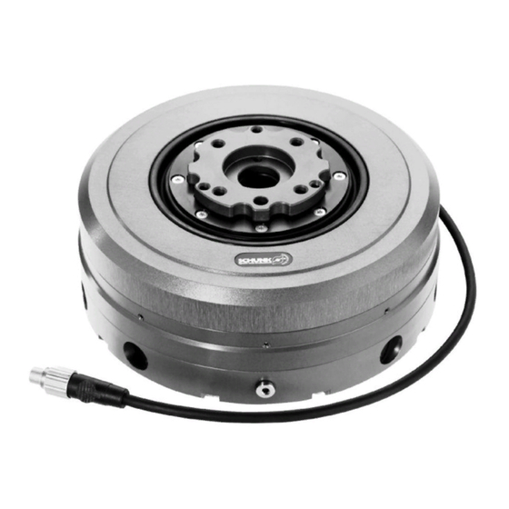
- Page 1 Force-torque Sensor Type FTC / FTCL Assembly and Operating Manual 02-A/FTC/en/2009-12-28/SW Document-last updated: 2008-11-14...
- Page 2 Dear Customer, Congratulations on choosing a SCHUNK product. By choosing SCHUNK, you have opted for the highest precision, top quality and best service. You are going to increase the process reliability of your production and achieve best machining results – to the customer's complete satisfaction.
-
Page 3: Table Of Contents
Safety-conscious working................. 10 Notes on particular risks ................10 Warranty ......................11 Scope of delivery ....................11 Technical Data ....................12 FTC ......................12 FTCL ......................13 Assembly ......................14 Mechanical connection ................14 Air connection ..................17 Electrical connection (data interface) ............18 6.3.1... - Page 4 10.3.4 Ground short in spring ..............53 10.3.5 EEPROM Checksum2 ..............53 10.3.6 EEPROM Part B deleted ............. 53 10.3.7 EEPROM TIMEOUT ..............54 10.3.8 Horizontal current fault ..............54 10.3.9 Vertical current fault ..............55 10.3.10 CAN controller defective .............. 55 02/FTC/en/2009-12-28/SW...
- Page 5 About this manual Test software ....................... 56 Contact ........................ 57 02/FTC/en/2009-12-28/SW...
-
Page 6: About This Manual
You can find the following documents on our homepage: Document Purpose Catalog Technical data or application parameters of the module and information on accessories. The last version is always valid. General terms of busi- Including notes on the warranty. ness Tab. 2 02/FTC/en/2009-12-28/SW... -
Page 7: Symbols In This Manual
Handling instruction, also measures in a warning or note. . Step-by-step handling instruction. Observe the order. 3..(10) Reference in the text or in a handling instruction to a part that is rep- resented in a graphic. Tab. 3 02/FTC/en/2009-12-28/SW... -
Page 8: Basic Safety Notes
Make sure that the environment is free from splash water and vapors as well as from abrasion or processing dust. Excepted are modules that are designed specially for contaminated environments. 02/FTC/en/2009-12-28/SW... -
Page 9: Controlled Production
Directive. 2.3.2 Constructional changes, attachments, or conversions Additional drill holes, threads, or attachments that are not offered as accessories by SCHUNK may be attached only with permission of SCHUNK. Personnel qualification The assembly, initial commissioning, maintenance, and re- pair of the module may be performed only by trained spe- cialist personnel. -
Page 10: Safety-Conscious Working
For all work, secure the module against accidental operation. Risk of injury from spring forces! Modules that clamp with spring force are under spring ten- sion. The disassembly of the module may be performed only by trained specialist personnel. 02/FTC/en/2009-12-28/SW... -
Page 11: Warranty
Parts touching the workpiece and wearing parts are not part of the warranty. Also observe our general terms of business. Scope of delivery The scope of delivery includes: • Force-torque Sensor Type FTC / FTCL in the ordered model: • Software for PC-Connection •... -
Page 12: Technical Data
Technical Data Technical Data Further technical data can be found in our catalog. The most recent version applies. Type FTC- FTC- FTC- FTC- 050-80 050-80-V 050-40 050-40-V Deadweight [kg] 1,56 2,56 1,56 2,56 Permissible operating temperature +5 to +55 [°C]... -
Page 13: Ftcl
Measuring range translatory (X,Y,Z) [mm] +/- 1,0 Measuring range rotary (α,β,γ) [°] +/- 1,0 Measuring frequency [kHz] Power supply [VDC] 10 to 26 Max. Power consumption [W] RS232 (RS485 on request) Electrical interfaces CAN (DeviceNET on request) Tab. 5 02/FTC/en/2009-12-28/SW... -
Page 14: Assembly
Module with pre-assembled 4 x M6 cheese-head Without locking screws, fasten to robot. With locking 1. Locking unit with 4 x M6 cheese-head screws, fasten to robot. 2. Sensor unit with pre-assembled 4 x M6 cheese-head screws, fasten to locking unit.. 02/FTC/en/2009-12-28/SW... - Page 15 Mounting surface (tool-side) with ISO 9409-1-A50 interface M6 / 11 (4x) Ø 18 Fully through M5 / 11 (3x) for direct mounting on PZN 64 Centering pin Ø 6 / 12.5 Mounting surface (robot-side) with ISO 9409-1-A50 interface Fig. 1 FTC flange pattern 02/FTC/en/2009-12-28/SW...
- Page 16 Assembly Centering pin Ø 6 Mounting surface (tool-side) with ISO 9409-1-A50 interface M6 / 7 (4x) Ø 26 Fully through Mounting surface (robot-side) with +0.2 ISO 9409-1-A50 interface Centering pin Ø 6.5 / 8.5 Fig. 2 FTCL flange pattern 02/FTC/en/2009-12-28/SW...
-
Page 17: Air Connection
Assembly Air connection Only for modules with locking (FTC-050-80-V / FTC-050-40-V) WARNING Risk of injury when the machine/system moves unexpectedly! Switch off energy supply Air connection, outer side Air connection , tool-side Fig. 3 Connection thread M5 / 5... -
Page 18: Electrical Connection (Data Interface)
Default 9600 can be set via software Handshake none Data bits Stop bits Tab. 7 • Pin assignments Possible sensor plugs • Binder plug • SubD 12..24V RS232:Rx RS485:A Can_H RS485:B Can_L Housing Shielding RS232:Tx Fig. 4 Binding plug at sensor 02/FTC/en/2009-12-28/SW... - Page 19 Additionally bridged in plug: 7 and 8 (RTS to CTS) 4 and 6 (DTR to DSR) Fig. 5 SubD plug at sensor Cable lengths Maximum cable length depends on the cable used and the Baudrate. Standard: at 9600 Baud max. 30 Meters. 02/FTC/en/2009-12-28/SW...
-
Page 20: Canbus
Shielding Shielding Tab. 8 If necessary, a termination resistor (usually 120 Ohm) may need to be connected at the transmitter end. Information on transmitting and receiving data and the pro- gramming commands is provided in Chapter 8, page 25. 02/FTC/en/2009-12-28/SW... -
Page 21: Setting The Dip Switch
The DIP switch is located on the bottom of the housing. The connection plate must be removed to set the DIP switch. Fig. 7 Connection plate position 1. For modules with locking (FTC-050-80-V / FTC-050-40- V) the locking unit must first be removed in order to remove the connection plate. - Page 22 The force torque sensor is switched to flash mode. This set- ting is only required if the force torque sensor cannot be switched to flash mode via the software. (forgotten pass- word, power failure during a previous software update) 02/FTC/en/2009-12-28/SW...
- Page 23 Destruction of the force torque sensor when the wrong screws are used! When mounting the connection plate, make sure that the long and short fastening screws are screwed into the correct positions. 1 Screws long 2 Screws short Fig.9 Connection screws on the cover plate 02/FTC/en/2009-12-28/SW...
-
Page 24: Operating Display
Rhythmic blinking One of the two interfaces is not green-red working properly Irregular blinking Defective firmware in sensor red-green Green irregular blinking Data is being transferred No display Sensor is switched off or in FLASH mode Tab. 10 02/FTC/en/2009-12-28/SW... -
Page 25: Controlling / Programming
• Other commands Most commands can be sent over the serial interface using a terminal program for test purposes 02/FTC/en/2009-12-28/SW... -
Page 26: Commands
3x16 bit values (INT16) Fx,Fy,Fz Seriell : 1x16 bit statusword CAN : 1x8 bit statusword Note In a transmission by CAN the statusword is shortened that all data can be transmitted in one message Conversion INT [N] : /32 Tab. 13 02/FTC/en/2009-12-28/SW... - Page 27 2 / 10 = Fz bit 3 / 11 = Mx bit 4 / 12 = My bit 5 / 13 = Mz bit 6 / 14 reserved bit 7 / 15 reserved 1x16 bit statusword Note Tab. 15 02/FTC/en/2009-12-28/SW...
- Page 28 3x16 bit values (INT16) X,Y,Z Serial : 1x16 bit statusword CAN : 1x8 bit statusword Note In a transmission by CAN the statusword is shortened that all data can be transmitted in one message Conversion INT [mm] : /4096 Tab. 18 02/FTC/en/2009-12-28/SW...
- Page 29 2 / 10 = Z bit 3 / 11 = A bit 4 / 12 = B bit 5 / 13 = C bit 6 / 14 reserved bit 7 / 15 reserved 1x16 bit statusword Note Tab. 20 02/FTC/en/2009-12-28/SW...
- Page 30 1x16 bit Status : below 8bit = measuring range exceeded Note As of Firmware 2.00a + measuring cells with acceleration sensors (optional) If this command does not work despite an in- stalled acceleration sensor (Unknown com- mand), then at least one acceleration sensor is faulty. Tab. 23 02/FTC/en/2009-12-28/SW...
- Page 31 When transferring over CAN, the last 16 bits are shortened to 8 bits so that all data fits into a single CAN message. Conversion INT Acceleration values [m/sec ] *128.0 Tab. 25 02/FTC/en/2009-12-28/SW...
-
Page 32: Settings Functions
When successfully executed 19279 0x4B4F ‚OK„ Sensor 20567 0x5057 ,WP„ else Note The operating mode of the communication can be set using this. Valid values : • "RS 232","RS 485" (as of HW 3.2), • “CAN[SPACE][SPACE][SPACE]“, • “ DEVNet" (optional, must be enabled) Tab. 27 02/FTC/en/2009-12-28/SW... - Page 33 20567 0x5057 Note Baudrate is transmitted by 4 char; valid values in kBaud: 0010, 0025, 0050, 0100, 0125, 0250, 0500, 0800, 1000 If the transmission is successful the sensor will reboot with the new adjustments Default: 500 [kBaud]. Tab. 29 02/FTC/en/2009-12-28/SW...
- Page 34 If transmission is successful 20567 0x5057 ,WP„ else Note Producer Size is transmitted by 3 Char valid Values : 000 – 028 If DEVNet is present and activated then the Producer Size can be set using this. Tab. 31 02/FTC/en/2009-12-28/SW...
- Page 35 ”set position limit” to the sensor Wait for the answer: 0x93 (acknowledge) + 0x07 (number of ex- pected Bytes) Send ”B-0.56+1.783xxx” to the sensor The sensor should answer with ”OK” The new positionlimit was adjusted successful- ly and is active now. 02/FTC/en/2009-12-28/SW...
- Page 36 Wait for the answer: 0x93 (acknowledge) + 0x07 (valid of expected bytes) Send ”Fy-012.00 + 020.34” to the sensor The sensor should answer with ”ok” The new position limit was adjusted success- fully and is active now. Tab. 32 02/FTC/en/2009-12-28/SW...
- Page 37 0x79 (acknowledge) + 0x02 (number of ex- pected bytes) send ”B+” to the sensor. The sensor should answer with ”OK” => the new position limit was adjusted successfully and is active now. Only available in software version 1.10a or later Tab. 33 02/FTC/en/2009-12-28/SW...
- Page 38 The set value is stored in EEPROM. Caution! If the last command to one of the sensors was a "Settings command" then this can lead to unpredictable results. This function is available as of Firmware Ver- sion 1.30a Tab. 35 02/FTC/en/2009-12-28/SW...
-
Page 39: Commands For Information
Answer appears in uncoded text (bytes=ASCII code) The maximum force range is read from the sensor and the programmed values are displayed X +01.500 –01.500 | +01.000 - 00.916 [mm ] Maximum force range | adjusted value Tab. 37 02/FTC/en/2009-12-28/SW... - Page 40 1x16 bit (INT16) value: Number of the follow- ing bytes Note Answer appears in uncoded text (bytes = ASCII Code). All important sensor information (hardware version, software version, number of compliant elements, built in DSPs, number of successful executed boot events) Tab. 39 02/FTC/en/2009-12-28/SW...
-
Page 41: Other Functions
As of Firmware Ver. 1.30a Tab. 41 Reset ASCII ‚0„ Command 48 0x30 ‚1„ Answer 0x31 ‚OK„ 19279 0x4B4F Note Sensor is executed a complete reset and will reboot. In a case of an error the function will be executed too. Tab. 42 02/FTC/en/2009-12-28/SW... - Page 42 Caution! If the last command to one of the sensors was a "Settings command" then this can lead to unpredictable results. Tab. 44 02/FTC/en/2009-12-28/SW...
- Page 43 Get Rotation INT the status word is shortened for CAN re- quests. ((bit 0-3 OR bit 4-7) + (bit 8-11 OR bit 12-15)) This means that an assignment of which PSD has caused an error is only partially possible! 02/FTC/en/2009-12-28/SW...
-
Page 44: Options
"A" in the Hardware Version (Sensor Info HW: 3.xx A) This option can be retrofitted to all sensors. Commands for reading the acceleration are implemented as of Firmware 2.00a. If an acceleration sensor is defective then commands for reading acceleration can no longer be sent. 02/FTC/en/2009-12-28/SW... -
Page 45: Error Messages
0x21 Tab. 45 This is followed by a 16 bit (INT16) value containing an ex- act error description. Error messages are output to all interfaces. The error messages are subdivided into: • Warnings • Correctable errors • Serious errors 02/FTC/en/2009-12-28/SW... -
Page 46: Warnings
Acceleration, rotary Tab. 46 10.1.2 Wrong Parameter ASCII Error code ‚WP„ 20567 0x5057 Possible cause Corrective action Send the correct parameter The wrong parameter or password was sent to the sensor send the correct password Tab. 47 02/FTC/en/2009-12-28/SW... -
Page 47: Correctable Errors
Error code ‚e1„ 12645 0x3165 Possible cause Corrective action Set Default boot (see Chapter 6.4, Part A of the EEPROM has been deleted. Page 21). If this does not correct the error then the EEPROM is defective. Tab. 49 02/FTC/en/2009-12-28/SW... -
Page 48: Invalid Serial Baudrate
Serial defective ASCII Error code ‚Xs„ 0xXX73 Possible cause Corrective action The sensor attempts to independently Serial interface has a problem solve the problem. If this error message occurs frequently then the sensor serial interface is defective. Tab. 52 02/FTC/en/2009-12-28/SW... -
Page 49: Invalid Can Baudrate
Invalid MAC ID ASCII Error code ‚cI„ 18787 0x4963 Possible cause Corrective action Set a valid MAC ID Invalid MAC ID Set Default boot (see Chapter 6.4, Page 21): MAC ID set to 5, valid Tab. 54 02/FTC/en/2009-12-28/SW... -
Page 50: Can Timeout
DEVNet Size ASCII Error code ‚cS„ 21347 0x5363 Possible cause Corrective action Adjust the DEVNet Producer Size or DEVNet Producer Size is too small switch to CAN operation. Send the command via the serial interface Tab. 57 02/FTC/en/2009-12-28/SW... -
Page 51: Input Voltage Too High
Input voltage too high LED lights RED continuously! Tab. 58 10.2.12 Input voltage too low ASCII Error code ‚VL„ 19542 0x4C56 Possible cause Corrective action Increase input voltage to 11..26 V! Input voltage too low LED lights RED continuously! Tab. 59 02/FTC/en/2009-12-28/SW... -
Page 52: Serious Errors
Determined when the sensor is started up: The measuring cell is defective Tab. 61 10.3.3 Broken spring ASCII Error code ‚S‘ 0x0053 Possible cause Corrective action Send the FCT Force torque sensor to Defective elastic element in sensor. SCHUNK Tab. 62 02/FTC/en/2009-12-28/SW... -
Page 53: Ground Short In Spring
10.3.6 EEPROM Part B deleted ASCII Error code ‚e2„ 12901 0x3265 Possible cause Corrective action Send the Force torque sensor to EEPROM Part B has been deleted SCHUNK The EEPROM has been manipulated or is defective. Tab. 65 02/FTC/en/2009-12-28/SW... -
Page 54: Eeprom Timeout
18499 0x4843 Possible cause Corrective action Send the Force torque sensor to Current fault in the horizontal measuring system SCHUNK The current in the horizontal measuring system is too low => a measuring cell is defective Tab. 67 02/FTC/en/2009-12-28/SW... -
Page 55: Vertical Current Fault
=> a measuring cell is de- fective Tab. 68 10.3.10 CAN controller defective ASCII Error code ‚cC„ 17251 0x4363 Possible cause Corrective action Replace the CAN controller CAN controller defective The sensor can only be operated via the serial interface. Tab. 69 02/FTC/en/2009-12-28/SW... - Page 56 A terminal program is required for operating the Force torque sensor. Terminal program settings Parity none Baudrate Baudrate programmed into sensor (default 9600) Handshake none Data bit Stop bit Tab. 70 All settings functions and information functions can be per- formed using this. 02/FTC/en/2009-12-28/SW...
- Page 57 Contact Contact GERMANY – HEAD OFFICE CANADA DENMARK HUNGARY SCHUNK GmbH & Co. KG SCHUNK Intec Corp. SCHUNK Intec A/S SCHUNK Intec Kft. Spann- und Greiftechnik 190 Britannia Road East, Storhaven 7 Széchenyi út. 70. Bahnhofstrasse 106 – 134 Units 23-24...
- Page 58 Fax +82-31-7376142 info@kr.schunk.com www.kr.schunk.com MEXICO, VENEZUELA PORTUGAL SPAIN TURKEY SCHUNK Intec S.A. de C.V. Sales Representative SCHUNK Intec S.L. SCHUNK Intec Bağlama Sistemleri ve Av. Luis Vega y Monroy # 332 Victor Marques Foneria, 27 Otomasyon San. ve Tic. Ltd. Şti.
Need help?
Do you have a question about the FTC and is the answer not in the manual?
Questions and answers