OJ Electronics ICD3-1999 Instructions Manual
Hide thumbs
Also See for ICD3-1999:
- User manual (12 pages) ,
- User manual (13 pages) ,
- User manual (12 pages)
Table of Contents
Advertisement
Available languages
Available languages
Quick Links
67068-06-11.qxd:57627B
29/06/11
IN ST RUCT I ON S
Type ICD3-1999
67068 06/11 (MBC)
English
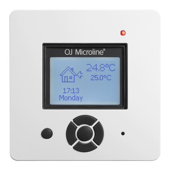
The electronic comfort controller is a clock
thermostat that can be programmed to function
as a floor temperature controller and room
temperature controller with a limitation function.
The thermostat is intended for mounting in a
55 mm standard wall socket. The operating area
ranges from +0° to +30°C. The thermostat
incorporates a clock enabling the programming
of several setback functions.
Controller setting ICD3
Program choice:
Floor temperature control
Floor temperature control with 2 sensors
Air temperature control
Air temperature control with floor
temperature limit
Regulator control
External control
The controller is designed in accordance
with current product standard EN 60730-2-
9, and fulfill hereby the requirements to
both LVD and EMC directives.
The controller must not be put into operation
until it has been ascertained that the entire
installation complies with current general safety
requirements for electrical installations.
Technical data
Supply voltage . . . . . . . . . . .230V ±10%, 50 Hz
Output relay SPST . . . . . . . . . . . . . .16A, 3600W
Temperature range . . . . . . . . . . . . . . . .+0/+30˚C
Temperature limitation . . . .min./max. +5/+55˚C
Clock function . . . . .1 pre-installed programmes
28 optional setback programmes
Ambient temperature . . . . . . . . . . . . . . .0/+30˚C
On/off differential . . . . . . . . . . . . . . . . . . . .0,4˚C
Housing . . . . . . . . . . . . . . . . . . . . . . . . . . .IP 20
Sensor type . . . . . . . . . . . . . . . . . . . . . . . . .NTC
- heating is switched off in case of sensor failure
Dimensions (HxWxD) (fig. 6) . . . . .86/86/48 mm
The controller is maintenance-free.
Control pollution degree: 2
Pollution degree 2 is representative of normal
household air circulation.
Overvoltage category: III
Classification
The product is a class II device (reinforced
insulation) and the product must be connected
to the following conductors:
1) Phase (L)
2) Neutral (N)
The thermostat is constructed to store the clock
up to 4 hours at an occasional voltage
interruption. It is not suitable for use by regular
voltage interruptions. (Example: Power term
applications). At such conditions a constant
power supply for the thermostat must be
ensured.
WARNING – Important Safety Instructions
Isolate supply before carrying out any
installation or maintenance work on this control
unit and associated components. This control
unit and associated components should only be
9:03
Side 1
installed by a competent person (i, e qualified
electrician). Electrical installation to be in
accordance with latest IEE Wiring Regulations
and appropriate Statutory Regulations.
Mounting of sensor
Floor sensor: Placed in an approved non
conductive installation pipe in accordance with
EN 61386-1, which is embedded in the floor.
(fig. 3). The pipe is closed in the end and placed
as high as possible in the concrete layer. The
installation pipe must be centered in between
the heating cable.
The enclosed 3 meter sensor cable can be
extended up to 100 m by means of a separate
cable. If the extension cable is lighter than
H05VV-F, it shall equally be installed in an
unbroken installation pipe between the sensor
cable and the extension cable. Two remaining
cores of a multi-core cable which, for example,
supplies current to the heating wires of a floor
heating system, must not be used. The
switching peaks of such current supply lines
may create interfering signals that prevent
optimum controller function. The two-corecable
must be placed in a separate pipe.
Controller installation site
The controller must be mounted on the wall so
that air can circulate freely around it (fig. 4). An
installation site must be selected where the
controller is not exposed to foreign energy
sources, e.g. solar radiation. The controller must
not be exposed to draughts coming from, for
example, windows, doors or cold outer walls.
The controller has a built-in fault interrupter
circuit which interrupts the heating in case of
disconnected or short-circuited sensor.
The single gang mounting box must have a
debt of no less than 25 mm.
1. Use a screwdriver in both sides to open the
lock.
The cover must be dismounted (fig. 1).
2. Connect cables according to the diagram
(fig. 2a-2b).
All electrical connections must be performed by
a fully qualified and Part P certified electrician.
3. Place the screws in front through the holes in
the thermostats and mount them in the wall
socket. The cover is remounted.
(See user manual)
The controllers are delivered with a pre-installed
setback programme.
If the pre-installed setback programme is not
used, there are different programmes which can
be selected and used on the required days.
The controllers calculate when the heating is to
be switched on to make sure that the comfort
temperature is obtained to the required time.
If the sensor is disconnected or short-
circuited, the heating system is switched off.
The sensor can be checked according to the
resistance table fig. 5.
© 2011 OJ Electronics A/S
Please help us to protect the environment by
disposing of the packaging in accordance with
the national regulations for waste processing.
Appliances with this label must not
be disposed off with the general
waste. They must be collected
separately and disposed off
NW107UW-A
according to local regulations.
OJ ELECTRONICS A/S
Stenager 13B · DK-Sønderborg · Denmark
T. +45 73 12 13 14 · F. +45 73 12 13 13
oj@ojelectronics.com · www.ojelectronics.com
Español
El controlador electrónico de confort es un
termostato cronometrado que se puede
programar para funcionar como controlador de
temperatura del piso y como controlador de
temperatura ambiente con una función
limitadora.
El termostato está diseñado para montaje en un
receptáculo de pared estándar de 55 mm. Los
límites de funcionamiento son de 0° a +30 °C.
El termostato incorpora un reloj que permite la
programación de varias funciones de reducción
de temperatura.
Ajuste de controlador ICD3
Opción de programa:
Control de temperatura de piso
Control de temperatura de piso con 2
sensores
Control de temperatura del aire
Control de temperatura del aire con límites
de temperatura de piso
Control regulador
Control externo
El controlador está diseñado de acuerdo
con las normativas de producto vigentes
EN 60730-2-9, y por lo tanto cumple los
requisitos de las directivas LVD y EMC.
No se debe accionar el controlador antes de
verificar que toda la instalación cumpla con los
requisitos vigentes de seguridad general para
instalaciones eléctricas.
Datos técnicos
Tensión de alimentación . . .230 V ±10%, 50 Hz
Relé de salida SPST . . . . . . . . . . .16 A, 3600 W
Rango de temperatura . . . . . . . . . . . .+0/+30 °C
Limitación de temperatura .mín./máx. +5/+55 °C
Función del reloj . . . . . .1 programa preinstalado
. . . . . . . . . . .28 programas opcionales
. . . . . . . .de reducción de temperatura
Temperatura ambiente . . . . . . . . . . . . .0/+30 °C
Diferencial Activado/Desactivado . . . . . .0,4 °C
Protección . . . . . . . . . . . . . . . . . . . . . . . . . .IP 20
Tipo de sensor . . . . . . . . . . . . . . . . . . . . . .NTC
- Se apaga la calefacción si falla el sensor . . . . .
Dimensiones (Alt.xAxProf.) (fig. 6) .86/86/48 mm
El controlador no requiere mantenimiento.
Control del grado de contaminación: 2
El grado de contaminación 2 es representativo
de la circulación de aire en la vivienda.
1
Advertisement
Table of Contents

Related Manuals for OJ Electronics ICD3-1999


Summary of Contents for OJ Electronics ICD3-1999
- Page 1 Control del grado de contaminación: 2 unit and associated components. This control resistance table fig. 5. El grado de contaminación 2 es representativo unit and associated components should only be de la circulación de aire en la vivienda. © 2011 OJ Electronics A/S...
- Page 2 Netzspannung ..230 V ±10 %, 50 Hz unterbrochenem oder kurzgeschlossenem efectuadas por un electricista debidamente Ausgangsrelais SPST ..16 A, 3.600 W Fühler abschaltet. cualificado y con certificación Parte P. © 2011 OJ Electronics A/S...
- Page 3 εγκατάστασης ανάµεσα στο καλώδιο του Stenager 13B · DK-Sønderborg · Denmark Εξωτερικός έλεγχος αισθητήρα και το καλώδιο επέκτασης. ∆εν πρέπει T. +45 73 12 13 14 · F. +45 73 12 13 13 oj@ojelectronics.com · www.ojelectronics.com © 2011 OJ Electronics A/S...
- Page 4 - le chauffage est coupé en cas de panne de permanente para o termóstato. sonde O controlador determina quando deve ser Dimensions (HxLxP) (figure 6) ..86/86/48 mm © 2011 OJ Electronics A/S...
- Page 5 électricien qualifié et certifié Technische gegevens die de verwarming onderbreekt als de sensor «PV de réception ». Voedingsspanning ..230V ±10%, 50 Hz uitgeschakeld of kortgesloten wordt. © 2011 OJ Electronics A/S...
- Page 6 Kontrola temperatury powietrza z limitem układu ogrzewania podłogowego. Skoki napięcia temperatury podłogi w takim przewodzie zasilającym mogą tworzyć Kontrola regulatora sygnał zakłócający prawidłową pracę urządzenia. Kontrola zewnętrzna Przewód dwużyłowy należy umieścić w oddzielnej rurze. © 2011 OJ Electronics A/S...
- Page 7 67068-06-11.qxd:57627B 29/06/11 9:03 Side 7 Fig.1 Fig. 2a - Master slave function Fig. 2b Fig. 4 Fig. 3 Fig. 5 Fig. 6 © 2011 OJ Electronics A/S...
- Page 8 OJ ELECTRONICS A/S Stenager 13B · DK-Sønderborg · Denmark T. +45 73 12 13 14 · F. +45 73 12 13 13 oj@ojelectronics.com · www.ojelectronics.com The trademark is registered and belongs to OJ Electronics A/S · © 2011 OJ Electronics A/S...
Need help?
Do you have a question about the ICD3-1999 and is the answer not in the manual?
Questions and answers