Table of Contents
Advertisement
Advertisement
Table of Contents

Summary of Contents for Ericsson Ericofon
-
Page 2: Table Of Contents
CONTENTS General The build-up of the Ericofon General service rules Case BC-unit Springset Transmitter inset Induction coil Terminal box Dial Instrument cord 3.10 Tools Adjustment- and testing instructions for service workshop 4.1 Mechanical check and adjustment 4.2 Lubrication 4.3 Mechanical check 4.4 Electrical check... -
Page 4: General
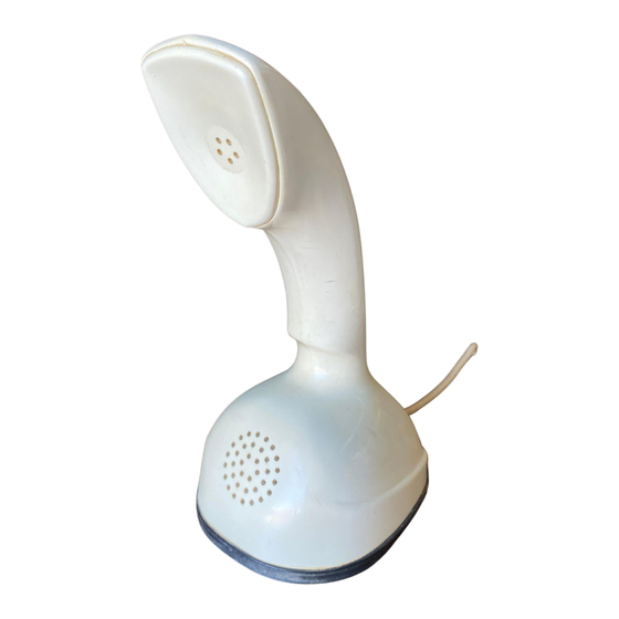
The millionth Ericofon was delivered during 1964. Photos 1 and 2 show three versions of the Ericofon: From the left, an Ericofon with earth button, a standard Ericofon, and a manual Ericofon. -
Page 5: The Build-Up Of The Ericofon
The earth button is removed from the housing by unscrewing the threaded nipple, fig. 6. The manual Ericofon (photo 7), which has no dial, has a much simpler mechanism than the other versions. - Page 6 By removing the screws holding the bracket in position the entire BC unit and buzzer can be lifted out. The buzzer can then be easily replaced, see figs. 15 and 16. The bearing plate which secures the impulse wheel (cam) intermediate gear and governor is mounted by means of a screw fig.
-
Page 7: General Service Rules
3. GENERAL SERVICE RULES The following instructions are intended for the service workshop and not for field service technicians sent out to correct faults at the subscribers. (Seethe special chapter concerning field service). 3.1 Case The receiver inset is permanently glued in the case. When the case is ordered as a spare part it is accompanied not only by the receiver inset but also the front fixing bracket 36165 and the rack rail 361166. -
Page 8: Induction Coil
3.9 Instrument cord Earlier types of Ericofon used a spiralized textile cord which has now been replaced with a spiralized PVC-cord. Each conductor in the cord consists of several copper wires. Depending on the installation, the Ericofon cord can be in one of several different forms. - Page 9 LMV 1091 The gram scales are used to adjust contact pressure according to the supplied adjustment instructions normal values LMT 1001 The feeler gauge is used when adjusting contact gap LMV 1111 and Weights to be used when determining spring LMV 1115 tension of the dial VRT 2503...
-
Page 10: Adjustment- And Testing Instructions For Service Workshop
4. ADJUSTMENT AND TESTING INSTRUCTIONS FOR SERVICE WORKSHOPS 4.1 Mechanical check All parts are checked as follows: (see spare parts list for reference) and adjustment Before assembling check that all the component parts are free from filings, burrs and other impurities. Check especially that the bearing surfaces are clean. - Page 11 Intermediate spindle (shaft (Figs. 37 and 38) The radial warpage of the gear wheel fig. in relation to the shaft (9) must not exceed ±0.05 mm and the axial warpage ±0.01 mm. The axial play of the gear wheel in relation to the intermediate shaft 0.07-0.1 should be min.
- Page 12 The minimum tension of the driving spring should be so large that if the first finger hole is loaded with a weight = 80 g and rotated towards the finger stop (position a, fig. 43), the finger wheel should return freely to its normal position (position b, fig.
- Page 13 make about the middle of the impulse springs' last but one make. Break should take place between springs 1 and 2 about the middle of the impulse springs' last break. The actuating foot of the lifting spring should be as close as possible to the centre gear wheel but clear of it when the finger wheel is depressed on dialling.
- Page 14 Lubrication (Fig. 55) Lubrication should be carried out with great care since the working order of the mechanism depends on it entirely. Since the details are treated in accordance with special instructions to prevent the lubricant from spreading over the surface, the surface treatment should not be damaged in any way.
- Page 15 The following rules must be observed very closely If not, the operation of the telephone will be endangered. The whole driving spring is lubricated before insertion in the spring housing, so no further lubricating should take place on assembling. The driving spring must not be touched with bare hands (fingers).
-
Page 16: Electrical Check
4.4 Electrical check Impulse ratio Check in the impulse tester in accordance with the following table: Impulse ratio make/break Nominal Range of tolerance 33/67 31-36 / 69-64 38/62 37-40 / 63-60 40/60 40-42 / 60-58 50/50 50-52 / 50-48 60/40 58-60 / 42-40 Impulse speed Check with frequency meter:... -
Page 17: Adjustment And Testing Instructions For Field Use
5. ADJUSTMENT AND TESTING INSTRUCTIONS FOR FIELD USE The service man's task should be simplified as much as possible before he is sent out to correct a reported fault. On the understanding that the customer wants his telephone working immediately, the service man should quite simply replace the faulty instrument with anew one. -
Page 18: Spare Parts
6. SPARE PARTS 6.1 Spare parts The Ericofon was brought into production in 1954 and over the past instruction years has been introduced into all of our world-wide markets. Since different telephone administrations have placed different demands on the telephone and since it has had many varying applications within the field of communications, the number of different types have been very large. -
Page 19: Location View And Spare Parts
14-37 in the spare parts list. Colour code table When ordering the Ericofon case, column 1, the colour must also be stated. The colour index can be found in the little table at the lower right-hand corner of the spare parts list.


Need help?
Do you have a question about the Ericofon and is the answer not in the manual?
Questions and answers