
Related Manuals for dymax BluWave QX4


Summary of Contents for dymax BluWave QX4
- Page 1 BlueWave User Guide ® ® Multi-Head LED Spot-Curing System ■ Instructions for Safe Use ■ Setup and Operation ■ Maintenance ■ Ordering Spare Parts and Accessories...
- Page 2 System designs enable stand-alone configuration or integration into your existing assembly line. Please note that most dispensing and curing system applications are unique. Dymax does not warrant the fitness of the product for the intended application. Any warranty applicable to the product, its application, and use is strictly limited to that contained in the Dymax standard Conditions of Sale.
-
Page 3: Table Of Contents
Safety ........................4 General Safety Considerations ................5 Specific Safety Considerations ................5 Dymax UV Light-Curing System Safety Considerations .......... 5 Product Overview..................... 8 Description of the BlueWave QX4 ................8 Features & Benefits of the BlueWave QX4 System ..........9 Validation ....................... -
Page 4: Introduction
Dymax LED light source. To use the BlueWave QX4 system safely, it must be set up and operated in accordance with the instructions given by Dymax. Using the system in any other manner will impair... -
Page 5: General Safety Considerations
BlueWave QX4 system. General Safety Considerations All users of Dymax LED light sources should read and understand this user guide before assembling and using the system. To learn about the safe handling and use of light-curable formulations, obtain and read the MSDS for each product. - Page 6 UV Exposure Figure 1. UV Spectrum Standard Dymax UV light-curing systems have been designed primarily to emit UVA and Visible energy (Figure 1). Depending on the type of LED head used, the energy emitted from the BlueWave QX4 can either be in the upper end of the UVA portion of the spectrum (PrimeCure®...
- Page 7 Flexible Film — Translucent UV-blocking, flexible urethane films can be used to quickly create workstation shielding. This UV-blocking, flexible urethane film is available from Dymax, call for assistance. High-Temperature Surfaces Surfaces exposed to high-intensity curing lights may rise in temperature. The intensity, distance, exposure time, cooling fans, and composition of the surface can all affect the rise in surface temperature.
-
Page 8: Product Overview
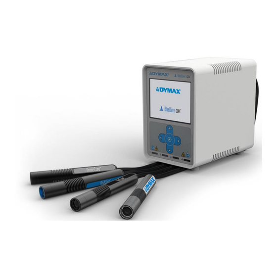
BlueWave® QX4® User Guide Product Overview Description of the BlueWave QX4 The BlueWave QX4 high-intensity spot-curing system features all the benefits of LED- curing technology in a smaller, more versatile unit. This system is comprised of a power supply, a controller with an easy-to-use control interface, and up to four LED heads. LED heads are available in 365, 385, and 405 nm and can be outfitted with 3-, 5-, or 8-mm diameter focusing lenses. -
Page 9: Features & Benefits Of The Bluewave Qx4 System
BlueWave® QX4® User Guide Features & Benefits of the BlueWave QX4 System The Dymax BlueWave QX4 is engineered for precise performance and long service life. Key features include: Features Benefits One controller controls up to four Provides maximum application flexibility LED heads ... -
Page 10: Front Control Panel
BlueWave® QX4® User Guide Set Intensity, Determine Exposure Time Users can specify light intensity and, through empirical testing, determine the exposure time required to achieve a full cure. As with any manufacturing process, it is advisable to incorporate a safety factor. Control Process validation confirms a minimum acceptable intensity. - Page 11 BlueWave® QX4® User Guide Figure 3. Front Control Panel Front Control Panel Display Run Button LED Head Indicators...
-
Page 12: Back Panel
Connection points for an interface with a user- supplied PLC (for remote operation). RS232 — ■ The RS232 port is a Dymax applicable troubleshooting port. No user functionality is available at this time. LED Head Connectors — ■ Connection points for up to four LED heads. Each connector corresponds to an available channel and indicator on the front panel. -
Page 13: Unpacking
Upon arrival, inspect all boxes for damage and notify the shipper of box damage immediately. Open each box and check for equipment damage. If parts are damaged, notify the shipper and submit a claim for the damaged parts. Contact Dymax so that new parts can be shipped to you immediately. -
Page 14: Led Heads & Lenses
BlueWave® QX4® User Guide To remove the LED Head, slide the retaining body of the Connector away from the Controller to unlock it from the Jack. Footswitch Connection — Located on the rear panel of the controller. It can be used as an optional irradiation trigger. - Page 15 BlueWave® QX4® User Guide Figure 6. Color-Coded LED Heads RediCure, 365 nm PrimeCure, 385 nm VisiCure, 405 nm Figure 7. Focus Lenses The focusing lens and collimating lens can be removed by unscrewing from the handle; however, removing the collimating lens is not recommended. (Error! Reference source not found.) Fixturing If fixturing the LED head, do not cover the cooling fins or overheating can result.
-
Page 16: Constant Mode
BlueWave® QX4® User Guide Operation WARNING! Looking directly at the high-intensity light emitted by the heads of the BlueWave QX4 can result in eye injury. To prevent eye injury, never look directly at the high-intensity light and always wear protective goggles (provided). Verify that all connectors are firmly plugged Figure 9. - Page 17 BlueWave® QX4® User Guide Set Up Figure 11. Constant Mode Menu In the constant mode menu, the user can see the current power and time configuration for each one of the LED Heads. To update any LED Head, navigate to the LED Head using the up and down buttons.
-
Page 18: Variable Mode
BlueWave® QX4® User Guide Irradiation Once all of the LED heads have been configured, navigate to the RUN option. Press the run button to start irradiation. Figure 14. Select Run Row Figure 15. Screen During Irradiation During irradiation, the time will count down to indicate the time remaining on the current curing session. - Page 19 BlueWave® QX4® User Guide Set Up On the variable mode menu (Figure 17), the user will see seven programs. Each program is a collection of steps and cycles. The programs are stored in local memory and can be used via the GUI interface or the PLC interface. Each LED Head can be programmed independently of the other LED Heads.
- Page 20 BlueWave® QX4® User Guide Figure 19. Edit Menu Figure 20. Steps Menu On the steps menu (Figure 20), the user can see the power and time settings for each step. To edit the step, navigate using the up and down buttons, then Right button to edit.
- Page 21 BlueWave® QX4® User Guide Irradiation Once all configurations are ready, navigate to the RUN row (Figure 23) using the up and down buttons. Press the center run button to start irradiation in all LED Heads. Figure 23. Select RUN Option Figure 24.
-
Page 22: Plc Operation
BlueWave® QX4® User Guide PLC Operation PLC operation mode can only be entered by Figure 25. PLC Mode Screen bringing the PLC sense input to a logic (0V). This will lock out the front control panel and will prevent the user from entering any commands using the front buttons. - Page 23 BlueWave® QX4® User Guide Inputs SIGNAL NAME/ ASSERTED DEASSERTED DESCRIPTION The unit enters PLC mode. The unit enters normal mode. The front panel will display The front panel will be the PLC screen. The front PLC SENSE unlocked. All PLC Inputs will panel will be locked.
- Page 24 BlueWave® QX4® User Guide Outputs *Output pins require a 10K pull up resistor to customer supplied 24V* SIGNAL NAME/ ASSERTED DEASSERTED DESCRIPTION LED head “n” is running a LED head “n” is not running a STATUS 1 ->4 program or is currently on. program and is currently off.
-
Page 25: 4-Channel Mode
BlueWave® QX4® User Guide 4-Channel Mode The BlueWave QX4 can be run in 4-channel mode through the Input Port on the back panel of the unit. This allows the unit to operate up to four LED heads independently with up to four separate footswitches. Proper connection and interface to external Programmable Logic Controllers will allow for independent and autonomous control of each LED Head channel. - Page 26 BlueWave® QX4® User Guide Figure 28. PLC Inputs & Outputs Input Logic Channel 1/2/3/4 Exposure Control (CH1/2/3/4 Start) Pulling CH1/2/3/4 pin to LOW (0) for 10mS or more will start irradiation on Wand 1/2/3/4, and follow their respective programmed power level and exposure time settings for such wand on each channel.
- Page 27 BlueWave® QX4® User Guide Interlock This pin enables or disables the operation of the device, even when the PLC mode is not active. Setting this pin to LOW (0) will enable all operations on the device, including LCD input and PLC control mode. Setting this pin to HIGH (1) will disable all operations on the device, including stopping any exposure operations currently taking place.
- Page 28 BlueWave® QX4® User Guide Figure 29.Connection Diagram To activate a channel, momentarily connect the channel input to the GND for 10 ms or more. The sink current required is approximately 10 mA. Channels that have a preset time will timeout and then stop. Individual channels that have time set to zero, will only activate if the connection to the GND is applied.
-
Page 29: System Settings
BlueWave® QX4® User Guide System Settings Figure 30. Select System Settings System settings allow the user to change the language, sounds, and temperature warnings. To enter this menu, navigate using the up/down buttons, then press right button to enter. Setting the Language To set the language, navigate to the first row, then press the right button to edit. - Page 30 BlueWave® QX4® User Guide Figure 33. Setting Adjustment Figure 34. Sound Options Screen Screen Temperature Warning Settings This is a user-defined temperature warning. The temperature-warning setting determines when the orange indicator light will come on. The head will continue to operate normally during the warning.
-
Page 31: Intensity Control Feature
BlueWave® QX4® User Guide Intensity Control Feature The components used in all light-curing systems degrade with use. Therefore, the maximum intensity decreases as exposure hours accumulate. Setting process intensity requirements lower than the maximum enables the BlueWave QX4’s intensity control feature to allow for compensation of gradual decreases in light intensity. - Page 32 BlueWave® QX4® User Guide the screen and remain until the wand has cooled to a safe operating temperature. The operator must then clear the warning screen before operation can resume. Figure 37. Cool-Down Screen Figure 38. Temperature Recovered Screen...
- Page 33 BlueWave® QX4® User Guide Table 2. Troubleshooting Chart for BlueWave LED QX4 Problem Possible Cause Corrective Action Check power connection and Power cord not plugged condition at power supply BlueWave QX4 does in or damaged “Brick” and controller. not power up No electrical power at Test Receptacle for power.
-
Page 34: Spare Parts And Accessories
Part Number Personal Protection Equipment Protective Goggles — Green 35286 Protective Goggles — Gray (standard model included with unit) 35285 Face Shield 35186 Radiometer Dymax ACCU-CAL™ 50-LED Radiometer (spot) 40505 LED Heads, 1.5 meter VisiCure 43161 PrimeCure 43162 RediCure 43163 Lens, Focusing ø3 mm, Spot... -
Page 35: Specifications
1 year from purchase date Operating Environment 5 - 40C [41-104F], non-condensing Recommended 40505 ACCU-CAL™ 50-LED Radiometer Accessories *Measured with 3-mm lens using Dymax ACCU-CAL™ 50-LED Radiometer, in spot mode at a distance of 5 mm. Figure 39. BlueWave QX4 Spectral Output... - Page 36 BlueWave® QX4® User Guide Figure 40. Dimensions - LED Heads Figure 41. Dimensions - Controller...
-
Page 37: Warranty
BlueWave® QX4® User Guide Warranty From date of purchase, Dymax Corporation offers a one-year warranty against defects in material and workmanship on all system components with proof of purchase and purchase date. Unauthorized repair, modification, or improper use of equipment may void your warranty benefits. -
Page 38: Index
BlueWave® QX4® User Guide Index 4-Channel Mode, 25 PLC, 22 Controller Set Up, 25 Product Overview, 8 I/O Connection, 25 Safety, 4 Back Panel Controls, 12 Safety of UV Light Cleaning the Lens, 31 Bright Visible Light, 7 Components, 8 High-Temperature Surfaces, 7 Connections, 13 UV Exposure, 6... - Page 39 BlueWave® QX4® User Guide...
- Page 40 U.S.A. Please note that most curing system applications are unique. Dymax does not warrant the fitness of the product for the intended application. Any warranty applicable to the product, its application and use is strictly limited to that contained in Dymax standard Conditions of Sale published on our website. Dymax recommends that any intended application be evaluated and tested by the user to ensure that desired performance criteria are satisfied.
Need help?
Do you have a question about the BluWave QX4 and is the answer not in the manual?
Questions and answers