Table of Contents
Advertisement
Quick Links
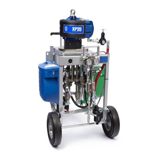
Operation, Repair, and Parts
™
XP
and XP-h
Proportioners
Mechanically linked fixed ratio plural-component system used for proportioning, mixing, and
spraying two component coatings. For professional use only.
Not approved for use in explosive atmospheres or hazardous locations except where indicated in
the Models section.
Important Safety Instructions
Read all warnings and instructions in this
manual and in related manuals before using
this equipment. Save these instructions.
See Models section (starting on page 10) for model
numbers, descriptions, and agency approval
designations.
™
3A0420ZAF
EN
Advertisement
Table of Contents


Need help?
Do you have a question about the XP-H Series and is the answer not in the manual?
Questions and answers