Graco XP70 Instruction & Parts Manual
Plural-component sprayer
Hide thumbs
Also See for XP70:
- Operation, repair, and parts (94 pages) ,
- Instructions manual (70 pages)
Table of Contents
Advertisement
Instructions-Parts
XP70
Plural-Component
Sprayer
Complete mechanical fixed ratio plural-component sprayer used for proportioning, mixing,
and spraying two component quick setting materials. For professional use only.
Important Safety Instructions
Read all warnings and instructions in this
manual. Save these instructions.
See page 11 for maximum working pressure and model
information.
Patents Pending
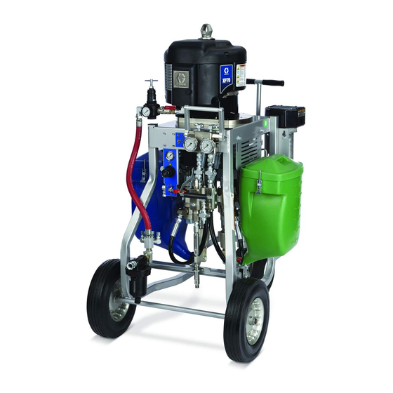
XP70 Sprayer shown with hoppers and optional
solvent flush pump and heaters.
3A0420H
EN
r_571100_3A0420A_1a-2
c IIA T2
II 2 G
Advertisement
Table of Contents
Troubleshooting

Related Manuals for Graco XP70


Summary of Contents for Graco XP70
- Page 1 Important Safety Instructions Read all warnings and instructions in this manual. Save these instructions. See page 11 for maximum working pressure and model information. XP70 Sprayer shown with hoppers and optional solvent flush pump and heaters. Patents Pending r_571100_3A0420A_1a-2 c IIA T2...
-
Page 2: Table Of Contents
Spray ........24 Graco Standard Warranty ....56 B Side Mix Manifold Restriction . -
Page 3: Related Manuals
Related Manuals Related Manuals Manuals are available at www.graco.com Component Manuals in English: Manual Description ® Xtreme Displacement Pumps 311762 Instructions-Parts ® 311238 Air Motor Instructions-Parts Mix Manifold 3A0590 Instructions-Parts 20 Gallon Double Wall Hopper Kit 312747 Instructions-Parts ® 309524... -
Page 4: Warnings
Warnings Warnings The following warnings are for the setup, use, grounding, maintenance, and repair of this equipment. The exclama- tion point symbol alerts you to a general warning and the hazard symbols refer to procedure-specific risks. When these symbols appear in the body of this manual, refer back to these Warnings. Product-specific hazard symbols and warnings not covered in this section may appear throughout the body of this manual where applicable. - Page 5 Warnings WARNING WARNING WARNING WARNING SKIN INJECTION HAZARD High-pressure fluid from gun, hose leaks, or ruptured components will pierce skin. This may look like just a cut, but it is a serious injury that can result in amputation. Get immediate surgical treatment. •...
- Page 6 Warnings WARNING WARNING WARNING WARNING TOXIC FLUID OR FUMES HAZARD Toxic fluids or fumes can cause serious injury or death if splashed in the eyes or on skin, inhaled, or swal- lowed. • Read MSDSs to know the specific hazards of the fluids you are using. •...
-
Page 7: Important Two-Component Material Information
• Keep the ISO pump wetcup or reservoir (if installed) also required for everyone in the work area. ™ filled with Graco Throat Seal Liquid (TSL ), Part 206995. The lubricant creates a barrier between the ISO and the atmosphere. -
Page 8: Changing Materials
, Xtreme- Epoxy and Urethane Hardener, Cata- ™ ™ Resin, Base Component Names , XM , and Protective Coatings lyst XP70 High Volume Low Volume Major or Minor Component Side Side (when not 1:1 mix) Letter Blue Color Epoxy, Silicone, Ure-... -
Page 9: Overview
XP70 sprayers are not approved for use in hazardous locations unless the base model, all accessories, all kits, and all wiring meet local, state, and national codes. -
Page 10: Initial System Setup
Initial System Setup Initial System Setup Complete the following steps in the order they are listed, as they apply to your specific system, for initial system setup. 1. Check the shipment for accuracy. Ensure you have received everything you ordered. See Component Identification, page 12. -
Page 11: Models
Cart-Mounted XP70 Sprayers All XP70 sprayers include static mixers, 3/8 x 25 ft hose, clean up mixer, 1/4 x 10 ft (x m) whip hose, and XTR 7 spray gun with a 519 tip. See Accessories and Kits on page 52 for a list of all optional accessories. -
Page 12: Component Identification
Component Identification Component Identification Mounting Components for Pump Package r_571101_3a0420a_1a-2 . 1: XP70 Sprayer with optional accessories Key: Air Motor Supply Hose Fluid Control Assembly; see page 13 Main Air Controls; see page 13 Tie Rods Air Inlet - 3/4 Npsm(F) -
Page 13: Fluid Control Assembly
Component Identification Fluid Control Assembly Key: AA Fluid Manifold AB Mix Manifold AC Circulation Handle AD Solvent Flush Valve AE Dual Shutoff Handle AF Fluid Pressure Gauges AG Fluid Supply Inlet (Behind Fluid Manifold) AH Fluid Circulation Fittings AJ B Component Adjustable Fluid Restrictor AK A and B Mix Manifold Check Valves AL Solvent Inlet Check Valve AM Automatic Over-Pressure Relief Valves;... -
Page 14: 45:1 Solvent Flush Pump Kit 262393 (Optional)
Component Identification 45:1 Solvent Flush Pump Kit 262393 (optional) Key: BA Solvent flush pump (Merkur Pump) BB Fluid Inlet BD Muffler BE Prime/Flush/Sample valve BF Fluid Outlet Hose BG Circulation hose BB (suction hose not shown) r_571100_3a0420a_4a-2 . 4: Solvent Flush Pump Kit Air Controls Included with optional solvent flush pump kit 262393. -
Page 15: Air Line
Component Identification Air Line Optional Accessories • Optional Fluid Heaters (N): to heat the resin and Bleed-type master air valve (CA): required in your sys- hardener before mixing. Improves the chemical tem to relieve air trapped between it and the air motor reaction and lowers viscosity to improve the spray when the valve is closed. -
Page 16: Setup
(Y) into lug (Z) slot and tighten locknut securely. Connect ground clamp to a true earth ground. Location XP70 sprayers are approved for use in hazardous locations only if the base model, all accessories, all kits, and all wiring meet local, state, and national codes. -
Page 17: Wire Sprayers With Explosion-Proof Heaters
Setup Wire Sprayers with Explosion-Proof Heaters (Hazardous location sprayers only) If your sprayer is rated for hazardous areas, and you have explosion-proof heaters, you must have a quali- fied electrician connect heater wiring. Ensure wiring and installation comply with local electrical codes for hazardous areas. -
Page 18: Air Motor Position
Setup Air Motor Position 2. Place wrench on adapter rod (104). 3. Use tool (70) to loosen the serrated yoke nut (V) The air motor position must be set for the mix ratio of the above the yoke (T). machine, which is defined by which two pumps are mounted. -
Page 19: Connect Air Supply
Setup Connect Air Supply Connect Fluid Hose Bundles (Remote Only) 1. Connect the air supply hose to the 3/4 npt(f) air filter inlet (C). Connect additional fluid hoses to the fluid manifold (AA) when the mix manifold (AB) is remote. Hoses must be NOTE: Use a 3/4 in. -
Page 20: Pressure Relief Procedure
Pressure Relief Procedure Pressure Relief Procedure 8. Engage the trigger lock. 9. Close the dual shutoff handle (AE) and open the cir- culation handle (AC). Follow Flush Mixed Material, page 26 when you stop spraying or dispensing; and before cleaning, checking, servicing, or transporting equipment. -
Page 21: Prime Empty Sprayer
Prime Empty Sprayer Prime Empty Sprayer Prime A and B Fluids 3. Move the recirculation lines (U) to empty containers. Wear gloves when using flush solvents and/or if the fluid temperature exceeds 110°F (43°C). NOTE: The equipment is tested with mineral oil at the factory. -
Page 22: Prime Solvent Flush Pump
Prime Empty Sprayer Prime Solvent Flush Pump 6. Ensure the trigger lock is engaged. Remove the spray tip. Follow instructions if the optional solvent flush pump kit is used. TI1949a 1. Connect the flush pail ground wire to a metal pail of TI1948a solvent. -
Page 23: Recirculate Or Re-Prime After A Pump Runs Dry
Prime Empty Sprayer Recirculate or Re-Prime After a 6. If the pumps are running too quickly, adjust the main air regulator (CB) to regulate the cycle rate. Pump Runs Dry 7. Run the pumps for a few minutes or until the mate- rial has reached the desired temperature. -
Page 24: Spray
Spray Spray 5. Engage the trigger lock. Install the tip on the gun. Wear gloves when using flush solvents and/or if fluid temperature exceeds 110°F (43°C). NOTE: After the first day of spraying follow Pressure TI1949a Relief Procedure, page 20, and tighten the throat packing nuts on both pumps. -
Page 25: B Side Mix Manifold Restriction
B Side Mix Manifold Restriction B Side Mix Manifold Restriction If the mix manifold (AB) is mounted on the machine, you The B side restrictor (AJ) controls “lead/lag” ratio errors do not need to adjust the restrictor (AJ). Leave open two of the A and B flow into the static mixer tubes. -
Page 26: Flush Mixed Material
Flush Mixed Material Flush Mixed Material 4. Open the solvent flush valve (AD). Flush the mix manifold when any of the following situa- tions occur. • breaks in spraying • overnight shutdown • end of potlife 5. Disengage the trigger lock and trigger gun into a grounded pail. -
Page 27: Empty And Flush Entire System (New Sprayer Or End Of Job)
Empty and Flush Entire System (new sprayer or end of job) Empty and Flush Entire System (new sprayer or end of job) 2. Engage the trigger lock. Turn the main pump air reg- ulator (CB) fully counter-clockwise to shut off. NOTE: •... -
Page 28: Shutdown
Shutdown 6. Run the pumps until the A and B hoppers (J) are 12. Close the dual shutoff handle (AE). empty. Salvage the material in separate, clean con- 13. Remove pump fluid filters, if installed, and soak in tainers. solvent. Clean and replace the filter cap. Always 7. -
Page 29: System Verification
System Verification System Verification Graco recommends running the following tests daily. NOTE: Spots that take longer to cure indicate insuf- ficient pump loading, leakage, or lead/lag errors at a remote mix manifold. Check for Normal Operation Every time you start spraying: Appearance Test •... -
Page 30: Maintenance
Maintenance Maintenance Filters 7. Clean the external surfaces only using a rag soaked in solvent that is compatible with the spray material and surfaces being cleaned. Once a week check, clean, and replace (if needed) the following filters. 8. Allow enough time for the solvent to dry before using the sprayer. -
Page 31: Troubleshooting
Troubleshooting Troubleshooting ✖ Fluid ratio will be wrong. ◆ Purge all air from system before proportioning fluids. Problem Cause Solution System stops or will not start. Air pressure or volume too low. Increase; check air compressor. Closed or restricted air line or air Open or clean. -
Page 32: Pump Troubleshooting
Troubleshooting Problem Cause Solution Fluid outlet pressure gauges split Not fully loading one side on Increase feed pressure on side that only at the top changeover (if one upstroke. dropped. gauge drops, the others will rise). Increase feed hose size. Clean inlet strainer or hopper screen. -
Page 33: Repair
Repair Repair 4. Remove the spring clamp (130) and coupling (119 or 120). To avoid serious injury due to the pump assembly falling, secure a hoist to the lift ring. Follow Shutdown, page 28, if service time may exceed pot life time, before servicing fluid components, and before transporting sprayer to a service area. -
Page 34: Air Controls
Repair Remove Air Motor 8. Refer to the air motor manual to service or repair the air motor. 1. Cycle the yoke and pump rods near the bottom of their stroke. Follow Shutdown, page 28. 9. Follow the steps in reverse order to reinstall the air motor. - Page 35 Repair Air Flow Air Flow 5, 8 r_571101_3A0420A_1a-2 . 8: Air Control Assembly 258983 3A0420H...
-
Page 36: Mix Manifold Assembly
Repair Mix Manifold Assembly 1. Follow Pressure Relief Procedure, page 20. 2. Disconnect the fluid hose (25) and the flush hose from the mix manifold (36). 3. Loosen the union fittings (306) that connect to the mix manifold adapter fittings. r_571101_3a0420a_39a 4. - Page 37 Repair 8. Place a handle (311) on a valve stem (302) at the vertical, or near vertical, spray position. 9. Apply blue threadlock on the nut (304) threads and tighten the handle against the spring (320) and clip (318). Torque to 70-80 in.-lbs. (7.9-9 N•m). 10.
-
Page 38: Hoppers
Repair Hoppers Solvent Pump 1. If material is in the hopper pump out the remaining 1. Follow Pressure Relief Procedure, page 20. material. 2. Disconnect the fluid line and air lines from the sol- 2. If the pump has failed: vent pump. -
Page 39: Optional Fluid Heaters
Repair Optional Fluid Heaters NOTE: Wiring for heaters is not provided. See the Vis- con HP heater manual for wiring, repair, and parts infor- mation for explosion-proof heaters. Service and Repair 1. Follow Pressure Relief Procedure, page 20. 2. Disconnect the fluid lines and electrical wiring from the fluid heater. -
Page 40: Parts
Parts Parts Cart-Mounted XP70 Sprayer Apply anaerobic pipe sealant to all non-swiveling pipe threads. r_571101_3a0420a_30a r_571101_3a0420a_30a 3A0420H... - Page 41 Parts Cart-Mounted XP70 Sprayer Continued 27, 28 27, 28 27, 28 r_571101_3a0420a_44a-1 r_571101_3a0420a_45a 49 “B” 49 “A” 65 (inside hopper) TI17434a 3A0420H...
- Page 42 Parts Common Parts Ref. Part Description Qty. 100333 SCREW, hex hd, sst; 1/4 x 1/2 zn Ref. Part Description Qty. 124293 BOLT, u-bolt, 3/8-16, 1 dia. 258913 CART 124259 BRAKE, plunger clamp 262476 AXLE, vertical 124291 PIN, spring 111841 WASHER, flat; 5/8 116704 ADAPTER, 9/16-18 JIC x 1/4 npt PACKAGE, pump;...
- Page 43 Parts Parts Varying by Model with Hoppers XP70 Plural-Component Sprayer Models Ref. Part Description 571102 571152 571202 571252 571302 571402 571100 PUMP, fixed ratio, 1:1 571150 PUMP, fixed ratio, 1.5:1 571200 PUMP, fixed ratio, 2:1 571250 PUMP, fixed ratio, 2.5:1...
-
Page 44: Bare Proportioning Pump Package
Parts Bare Proportioning Pump Package r_258914_3A0420A_3a r_258914_3A0420A_2a Torque together to 50-60 ft-lbs (68-81 N•m). Torque to 145-155 ft-lbs (196-210 N•m). Apply blue thread sealant. Insert lanyard from locking pin onto pumps (17, 18) as shown. Do not apply lubricant. Torque to 70-80 ft-lbs (95-108 N•m). Apply lithium grease to mating tapered surfaces. - Page 45 Ref. Part Description Qty. NXT102 KNOB, de-ice, 5 pack 262465 PLATE, motor 16D029 LABEL, XP70 262466 ROD, tie, 4.00 long,1.00 dia 124078 CLAMP, spring, constant-tension N65DN0 MOTOR, 6500, de-icing, standard 131▲ 15H108 LABEL, pinch point 262467 ROD, adapter 114225 TRIM, edge protection 262468 ROD, tie, 14.25 long, w/shoulder...
-
Page 46: Air Controls, 258983
Parts Air Controls, 258983 Air Flow Air Flow TI17433a r_571100_3A0420A_1a-1 1. Apply anaerobic pipe sealant to all non-swiveling pipe threads. Connect hose (214) to fitting (206) and air distribution manifold (213). Ref. No. Part No. Description Qty. Ref. No. Part No. Description Qty. -
Page 47: Fluid Manifold, 258990
Parts Fluid Manifold, 258990 r_258988_3a0420a_1b Apply anaerobic pipe sealant to all non-swiveling pipe Further tighten either valve (302) as required to line threads. up handle straight across. Torque to 28-32 ft-lbs (38-43 N•m). Apply grease to spring ends. Apply blue anaerobic adhesive to threads. Torque to 70-90 in.-lbs (7.9-9 N•m). -
Page 48: Recommended Spare Parts
Recommended Spare Parts Recommended Spare Parts Keep these spare parts on hand to reduce downtime. Pump Repair Kits See page 11 to see what pumps are used on your sprayer model. See lower manual for repair kits. Pump Filter O-rings (packs of 10) 262483, Top o-ring 244895, Middle o-ring 262484, Bottom o-ring... -
Page 49: Pump Performance Charts
Pump Performance Charts Pump Performance Charts Calculate Fluid Outlet Pressure Calculate Pump Air Flow/Consumption To calculate fluid outlet pressure (psi/MPa/bar) at a spe- cific fluid flow (gpm/lpm) and operating air pressure To calculate pump air flow/consumption (scfm or (psi/MPa/bar), use the following instructions and pump /min) at a specific fluid flow (gpm/lpm) and air pres- data charts. - Page 50 Pump Performance Charts Pump Performance Charts Continued 1.5:1 Mix Ratio 8000 (56, 560) (5.6) 7000 (49, 490) 6000 (4.4) (42, 420) (3.9) 5000 (35, 350) (3.3) 4000 (28, 280) (2.8) 3000 (2.2) (21, 210) 2000 (1.6) (14, 140) (1.1) 1000 (7, 70) (0.5) (1.9)
- Page 51 Pump Performance Charts Pump Performance Charts Continued 4:1 Mix Ratio 8000 (56, 560) (5.6) 7000 (49, 490) 6000 (4.4) (42, 420) (3.9) 5000 (35, 350) (3.3) 4000 (28, 280) (2.8) 3000 (2.2) (21, 210) 2000 (1.6) (14, 140) (1.1) 1000 (7, 70) (0.5) (1.9)
-
Page 52: Accessories And Kits
Green 7 Gallon Hopper Kit, 24F377 One splitter valve to use two spray guns with a propor- Mount to the sides of an XP70 sprayer. See manual tioner. It can be used with one gun or two and provides 406860 for more information. -
Page 53: Technical Data
Air inlet filtration ....... . . 40-micron filter/separator included XP70 pump outlets ....... 30 mesh XTR7 Spray Gun. -
Page 54: Dimensions
Dimensions Dimensions Bare System Full System Top VIew 35 in. 32 in. (889 mm) (812.8 mm) 52 in. (1320.8 mm) r_571100_3a0420_100a Side VIew 60 in. (1524 mm) r_571100_3a0420_101a 32 in. (812.8 mm) 22 in. 16.90 in. (558.8 mm) (429.26 mm) 15.25 in. -
Page 55: Bare Proportioner Mounting Hole Dimensions
Dimensions Bare Proportioner Mounting Hole Dimensions The dimensions below is the minimum opening size for mounting a bare proportioner. 7.5in. (190.5 mm) 3.75 in. 3/8-16 (4x) (95.25 mm) 120° (4x) 10.375 in. (263.525 mm) 2.25 in. 150° (4x) (57.15 mm) 9.25 in. -
Page 56: Graco Standard Warranty
With the exception of any special, extended, or limited warranty published by Graco, Graco will, for a period of twelve months from the date of sale, repair or replace any part of the equipment determined by Graco to be defective.
Need help?
Do you have a question about the XP70 and is the answer not in the manual?
Questions and answers