Table of Contents
Advertisement
Quick Links
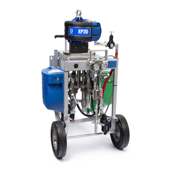
Operation, Repair, and Parts
™
XP
and XP-h
Proportioners
Mechanically linked fixed ratio plural-component system used for proportioning, mixing, and
spraying two component coatings. For professional use only.
Not approved for use in explosive atmospheres or hazardous locations except where indicated in
the Models section.
Important Safety Instructions
Read all warnings and instructions in this
manual and in related manuals before using
this equipment. Save these instructions.
See Models section (starting on page 10) for model
numbers, descriptions, and agency approval
designations.
™
3A0420ZAF
EN
Advertisement
Table of Contents

Related Manuals for Graco XP70-H


Summarization of Contents
Important Isocyanate (ISO) Information
Isocyanate Conditions
Explains hazards and precautions for handling isocyanates.
Moisture Sensitivity of Isocyanates
Details how moisture affects isocyanates and proper storage.
Changing Materials
Guidance on cleaning and changing materials to prevent damage.
Overview
Usage
Describes the purpose and included components of XP and XP-h systems.
Over Pressure Protection
Explains how the system protects against excessive fluid pressure.
Models
XP Proportioning Pump Packages
Details pump packages including motor, pump lowers, and hardware.
XP Models
Explains the part number code and lists XP models by ratio.
XP50-h with Viscount II Hydraulic Motor, Series C
Lists specifications and configurations for XP50-h models.
XP70-h with Viscount II Hydraulic Motor, Series C
Lists specifications and configurations for XP70-h models.
XP Proportioning Pump Packages
Details specific XP and XP-h pump packages with mix ratios.
Component Identification
XP Proportioners
Identifies components of the XP system with a diagram.
XP-h Proportioners
Identifies components of the XP-h system with a diagram.
Fluid Control Assembly
Details the components of the fluid control assembly.
Main Air Controls
Identifies main air controls for XP systems.
45:1 Solvent Flush Pump Kit 262393 (optional)
Identifies components of the optional solvent flush pump kit.
System Components
*Bleed Type Motor Air Valve (MA)
Explains the function and use of the bleed type motor air valve.
*Air Pressure Relief Valve (MG)
Describes the automatic pressure relief valve function.
*Air Filter (MC)
Explains the purpose of the air filter for clean compressed air.
*Air Regulator (MB)
Describes the function of the air regulator for pressure adjustment.
Fluid Line Components
Lists and describes various fluid line components.
Setup
Location
Provides guidance on positioning the proportioner for optimal use.
Initial System Setup
Outlines the steps for initial system setup and checks.
Grounding
Explains the importance of grounding to prevent static discharge and shock.
Connect Power
Details how to safely connect the system to a power source.
Systems with Explosion-Proof Heaters
Specific instructions for systems using explosion-proof heaters.
Motor Position
Explains the importance of setting motor position for the mix ratio.
Change Motor Position
Procedure for adjusting the air motor position for different mix ratios.
Connect Air Supply
Instructions for connecting the air supply hose to XP systems.
Connect Static Mixers, Gun, and Hoses
Details on connecting mixers, hoses, and the spray gun.
Connect Jacketed Heated Hose (Remote Mix Manifold Only)
Steps for connecting jacketed heated hoses.
Operation
Pressure Relief Procedure
Step-by-step guide to safely relieve system pressure before service.
Prime Empty System
Procedure for priming the system with A and B fluids.
Prime Solvent Flush Pump
Instructions for priming the solvent flush pump.
Recirculate Prior to Spraying or Re-Prime After a Pump Runs Dry
How to recirculate material and re-prime pumps for optimal performance.
Spray
Steps for preparing and performing spraying operations.
Flush Mixed Material
Procedures for flushing mixed material from the system.
Empty and Flush Entire System (new system or end of job)
Comprehensive guide to emptying and flushing the entire system.
System Verification
Daily tests recommended to ensure proper system operation.
Ratio Check
Procedure for checking the fluid mix ratio.
Maintenance
Cleaning Procedure
Steps for cleaning the equipment safely and effectively.
Change the Mix Ratio
Process for changing the system's mix ratio, including parts replacement.
Troubleshooting
Pump Troubleshooting
Chart to diagnose pump malfunctions based on gauge readings.
Repair
Remove Pump Assembly
Steps to safely remove the entire pump and motor assembly.
Remove Motor
Steps to remove the air motor from the pump assembly.
Replace Air Control Assembly
Steps for replacing the air control assembly.
Replace Over Pressure Relief Valves
Instructions for replacing over pressure relief valves.
Fluid Circulation Manifold with Over Pressure Relief Valves
Identification and repair of the fluid circulation manifold.
Hoppers
Procedures for servicing hoppers when the pump has failed.
Solvent Pump
Steps for removing and servicing the solvent pump.
Fluid Heaters
Information on servicing and repairing fluid heaters.
Parts
System Common Parts
Diagram and list of parts common to all XP systems.
Parts Varying by Model
Diagrams and lists of parts specific to different system models.
XP35 Systems
Part number and quantity list for XP35 systems.
XP50 Systems
Part number and quantity list for XP50 systems.
XP70 Systems
Part number and quantity list for XP70 systems.
XP-h Systems
Part number and quantity list for XP-h systems.
Recommended Spare Parts
List of recommended spare parts to maintain system readiness.
Accessories and Kits
Acceptable For Use in Explosive Atmospheres/Hazardous Locations
Lists accessories approved for hazardous locations.
Not Approved For Explosive Atmospheres
Lists kits that do not carry the EX mark.
Dimensions
Pump Dimensions
Dimensions of different pump packages (XP35, XP50, XP70).
Floor Mounting Dimensions, Top View
Dimensions for floor mounting the system.
Bare Proportioner Mounting Hole Dimensions
Specifies mounting hole dimensions for bare proportioners.
Technical Specifications
XP Proportioners
Lists key technical specifications for XP proportioners.
Weight:
Provides weight specifications for various system configurations.
Graco Standard Warranty
Graco Information
Information on obtaining the latest product details and patents.
Need help?
Do you have a question about the XP70-H and is the answer not in the manual?
Questions and answers