Table of Contents
Advertisement
Advertisement
Table of Contents

Related Manuals for Gigabyte MVBAYAI


Summary of Contents for Gigabyte MVBAYAI
- Page 1 MVBAYAI Intel Atom processor motherboard ® ® User's Manual Rev. 1001...
- Page 2 GIGABYTE's prior written permission. Documentation Classifications In order to assist in the use of this product, GIGABYTE provides the following types of documentations: For detailed product information, carefully read the User's Manual.
-
Page 3: Table Of Contents
Table of Contents Box Contents ........................4 MVBAYAI Motherboard Layout ..................5 Block Diagram .........................8 Chapter 1 Hardware Installation ..................9 Installation Precautions ..................9 1-2 Product Specifications ..................10 Installing the Memory ..................12 1-3-1 Installing a Memory ....................12 Back Panel Connectors .................. 13 Internal Connectors .................. -
Page 4: Box Contents
Box Contents Motherboard IO Shield *1 (12AIO-MVBAY0-00R) SATA 2.0 cable 500mm*1 (25CF4-500522-H3S) SATA power cable *1 (25CRI-100B00-H3R) • The box contents above are for reference only and the actual items shall depend on the product package you obtain. The box contents are subject to change without notice. •... -
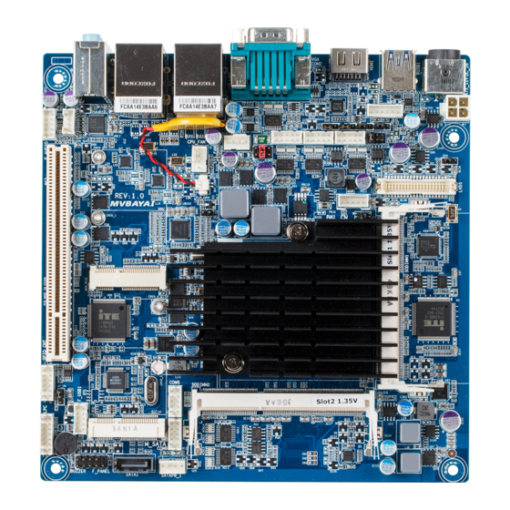
Page 5: Mvbayai Motherboard Layout
MVBAYAI Motherboard Layout 5 6 7 8 35 36 37 - 5 -... - Page 6 Item Code Description AUDIO Audio connectors RJ45 LAN port (top) / USB 2.0 ports USB_LAN1 (buttom) RJ45 LAN port (top) / USB 2.0 ports USB_LAN2 (buttom) VGA_COM2 Serial port (top) / VGA port (bottom) HDMI HDMI port KB_MS PS/2 Mouse/Keyboard cable connector RUSB1 USB 3.0 port DC_IN...
- Page 7 RS232/RS422/RS485 Select Jumper for JRS2 COM1 RS232/RS422/RS485 Select Jumper for JRS4 COM1 RS232/RS422/RS485 Select Jumper for JRS1 COM1 LVDS Panel GPIO Control jumper - 7 -...
-
Page 8: Block Diagram
Block Diagram - 8 -... -
Page 9: Chapter 1 Hardware Installation
Chapter 1 Hardware Installation Installation Precautions The motherboard contains numerous delicate electronic circuits and components which can become damaged as a result of electrostatic discharge (ESD). Prior to installation, carefully read the user's manual and follow these procedures: • Prior to installation, do not remove or break motherboard S/N (Serial Number) sticker or warranty sticker provided by your dealer. -
Page 10: Product Specifications
1-2 Product Specifications Support for Intel Celeron J1900 (2.0 GHz) processor Š ® ® TDP 10W Š L1/L2 cache varies with CPU Š Memory 2 x SO-DIMM slots support 1.35V DDR3L 1333/1600MHz Š Support up 16GB Š Audio Realtek ALC269 codec Š... - Page 11 CPU/system cooler you install. BIOS AMI BIOS Š Form Factor Mini ITX Form Factor; 170CM x 170CM Š GIGABYTE reserves the right to make any changes to the product specifications and product-related information without prior notice. - 11 - Hardware Installation...
-
Page 12: Installing The Memory
Installing the Memory Read the following guidelines before you begin to install the memory: • Make sure that the motherboard supports the memory. It is recommended that memory of the same capacity, brand, speed, and chips be used. • Always turn off the computer and unplug the power cord from the power outlet before installing the memory to prevent hardware damage. -
Page 13: Back Panel Connectors
Back Panel Connectors DC Power Jack Connect the DC power to this port. USB 3.0 Port The USB port supports the USB 3.0 specification. Use this port for USB devices such as a USB keyboard/mouse, USB printer, USB flash drive and etc. HDMI Port The HDMI (High-Definition Multimedia Interface) provides an all-digital audio/video interface to transmit the uncompressed audio/video signals and is HDCP compliant. Connect the HDMI audio/video device to this port. - Page 14 Connection/ Speed LED Activity LED Connection/Speed LED: Activity LED: State Description State Description Orange 1 Gbps data rate Blinking Data transmission or receiving is occurring Green 100 Mbps data rate No data transmission or receiving is occurring LAN Port 10 Mbps data rate • When removing the cable connected to a back panel connector, first remove the cable from your device and then remove it from the motherboard.
-
Page 15: Internal Connectors
Internal Connectors ATX_12V LVDS DC_IN JRS6 KB_MS SATA1 BKL_CN SATAPW_1 COM1 JCOM1 F_PANEL JRS3 F_USB1 JRS2 GPIO_CNT JRS4 F_AUDIO JRS1 SPK_OUT COM3 CPU_FAN JCOM3 SYS_FAN COM4 BAT_CON COM5 CLR_CMOS COM6 AT_CN - 15 - Hardware Installation... - Page 16 Read the following guidelines before connecting external devices: • First make sure your devices are compliant with the connectors you wish to connect. • Before installing the devices, be sure to turn off the devices and your computer. Unplug the power cord from the power outlet to prevent damage to the devices.
- Page 17 1) ATX_12V (2x4 12V Power Connector) With the use of the power connector, the power supply can supply enough stable power to all the components on the motherboard. Before connecting the power connector, first make sure the power supply is turned off and all devices are properly installed. The power connector possesses a foolproof design.
- Page 18 3) KB_MS (PS/2 Mouse/Keyboard cable connector) Pin No. Definition PS POWER MCLK MDATA KCLK KDATA 4) BKL_CN (LCD Inverter Connector) Pin No. Definition BLKCTL ENABKL +12V Hardware Installation - 18 -...
- Page 19 5) COM1 (Serial Port 1 Cable Connector)/JRS3/JRS2/JRS4/JRS1 6) JCOM1 (COM1 Select RS232/422/485 Jumper) 7/8/9/10) RS232/RS422/RS485 Select Jumpers for COM1) The COM header can provide one serial port via an optional COM port cable. For purchasing the optional COM port cable, please contact the local dealer. JRS3 JRS2 JRS4...
- Page 20 11/12) COM3/COM4 (Serial Port 3/4 Cable Connectors) COM3/COM4 COM3 COM4 COM4 COM3 Pin No. Definition Pin No. Definition NRXD3- NRXD4- NDCD3- NDCD4- NDTR3- NDTR4- NTXD3- NTXD4- NDSR3- NDSR4- NCTS3- NCTS4- NRTS3- NRTS4- RI3-/1.5V/12V NRI4- 13) JCOM3 (5V/12V/RI Signal Select Header for Serial Port 3) Pin No. Definition NRI3-(RI#) JCOM3...
- Page 21 14/15) COM5/COM6 (Serial Port 5/6 Cable Connectors) COM5/COM6 COM5 COM6 Pin No. Definition Pin No. Definition NRXD5- NRXD6- NDCD5- NDCD6- NDTR5- NDTR6- NTXD5- NTXD6- NDSR5- NDSR6- COM5 COM6 NCTS5- NCTS6- NRTS5- NRTS6- NRI5- NRI6- 16) JP2 (LVDS Panel GPIO 1 &2 Control Jumper ) Default 1024*768 1024*600...
- Page 22 17) LVDS (LVDS Connector) LVDS stands for Low-voltage differential signaling, which uses high-speed analog circuit techniques to provide multigigabit data transfers on copper interconnects and is a generic interface standard for high-speed data transmission. Pin No. Definition Pin No. Definition VCC3 A5P_C A4P_C...
- Page 23 18) JRS6 (LVDS Enable/Disable Jumper) 1-2 Close: Enable LVDS funciton. (Default setting) 2-3 Close: Disable LVDS funciton. Pin No. Definition DEBUG DDI1_HPD PORT HPDET_C 19) SATA1 (SATA 3Gb/s Connector) The SATA connectors conform to SATA 3Gb/s standard and are compatible with 1.5Gb/s standard. Each SATA connector supports a single SATA device.
- Page 24 20) SATAPW_1 (SATA HDD Power Connector) Pin No. Definition +12V 21) LPC (Low Pin Connector) Pin No. Definition 13 14 LAD0 +3.3V LAD1 -PLTRST2_N LAD2 -LFRAME LAD3 LPC25 SERIRQ_N Hardware Installation - 24 -...
- Page 25 22) F_PANEL (Front Panel Header) Connect the power switch, reset switch, speaker, and system status indicator on the chassis to this header according to the pin assignments below. Note the positive and negative pins before connecting the cables. Pin No. Signal Name Definition Hard Disk LED Signal anode (+) MPD+...
- Page 26 23) F_USB1 (USB Header) The headers conform to USB 2.0/1.1 specification. Each USB header can provide two USB ports via an optional USB bracket. For purchasing the optional USB bracket, please contact the local dealer. Pin No. Definition Power (5V) Power (5V) -FUSBP2 -FUSBP3 +FUSBP2 +FUSBP3 24) GPIO_CNT (GPIO connector) Pin No. Definition SOGPO_1 SOGPI_1 SOGPO_2 SOGPI_2 SOGPO_3 SOGPI_3 SOGPO_4 SOGPI_4...
- Page 27 25) F_AUDIO (Front Panel Audio Header) The front panel audio header supports Intel High Definition audio (HD) and AC'97 audio. You may connect your chassis front panel audio module to this header. Make sure the wire assignments of the module connector match the pin assignments of the motherboard header. Incorrect connection between the module connector and the motherboard header will make the device unable to work or even damage it. Pin No. Definition MIC_L MIC_R...
- Page 28 27/28) CPU_FAN/SYS_FAN (CPU Fan/System Fan Headers) The motherboard has one 4-pin CPU fan header (CPU_FAN), and one 4-pin (SYS_FAN) system fan headers. Most fan headers possess a foolproof insertion design. When connecting a fan cable, be sure to connect it in the correct orientation (the black connector wire is the ground wire). The motherboard supports CPU fan speed control, which requires the use of a CPU fan with fan speed control design.
- Page 29 30) CLR_CMOS (Clearing CMOS Jumper) Use this jumper to clear the CMOS values (e.g. date information and BIOS configurations) and reset the CMOS values to factory defaults. To clear the CMOS values, place a jumper cap on the two pins to temporarily short the two pins or use a metal object like a screwdriver to touch the two pins for a few seconds.
-
Page 30: Chapter 2 Bios Setup
Chapter 2 BIOS Setup BIOS (Basic Input and Output System) records hardware parameters of the system in the CMOS on the motherboard. Its major functions include conducting the Power-On Self-Test (POST) during system startup, saving system parameters and loading operating system, etc. BIOS includes a BIOS Setup program that allows the user to modify basic system configuration settings or to activate certain system features. When the power is turned off, the battery on the motherboard supplies the necessary power to the CMOS to keep the configuration values in the CMOS. - Page 31 Main This setup page includes all the items in standard compatible BIOS Advanced This setup page includes all the items of AMI BIOS special enhanced features. (ex: Auto detect fan and temperature status, automatically configure hard disk parameters.) Chipset Northbridge and Southbridge additional features configuration. Boot This setup page provides items for configuration of boot sequence. Security Change, set, or disable supervisor and user password. Configuration supervisor password allows you to restrict access to the system and BIOS Setup. A supervisor password allows you to make changes in BIOS Setup.
-
Page 32: The Main Menu
The Main Menu Once you enter the BIOS Setup program, the Main Menu (as shown below) appears on the screen. Use arrow keys to move among the items and press <Enter> to accept or enter other sub-menu. Main Menu Help The on-screen description of a highlighted setup option is displayed on the bottom line of the Main Menu. - Page 33 BIOS Information Project Name Display name of the project. BIOS Version Display version number of the BIOS. BIOS Build Date and Time Displays the date and time when the BIOS setup utility was created. LAN1/2 MAC Address Displays the LAN1 and LAN2 MAC address information. Memory Information Total Memory Display the total memory size of the installed memory.
-
Page 34: Advanced Menu
Advanced Menu The Advanced menu display submenu options for configuring the function of various hardware components. Select a submenu item, then press Enter to access the related submenu screen. BIOS Setup - 34 -... -
Page 35: Hardware Monitor
2-2-1 Hardware Monitor Press Enter to view the Hardware Monitor screen which displays a real-time record of the CPU/system tem- perature, and fan speed, Items on this window are non-configurable. PC Health Status CPU/System SMART FAN Function Enable CPU/System Fan Stop Warning function. Option available: Enabled/Disabled. Default setting is Enabled. CPU/System FAN Fail Detect Enable/Disable CPU/System FAN Fail Detect function. -
Page 36: S5 Rtc Wake Settings
2-2-2 S5 RTC Wake Settings Wake system from S5 Enable or disable System wake on alarm event. When enabled, System will wake on the hr:min:sec specified. Default setting is Disabled. Wake up hour (Note) Press <+> and <-> to define the wake up hour. Wake up minute (Note) Press <+> and <-> to define the wake up minute. Wake up second (Note) Press <+> and <-> to define the wake up second. -
Page 37: Cpu Configuration
2-2-3 CPU Configuration CPU Information Press [Enter] to view the installed CPUinformation. Intel Virtualization Technology Select whether to enable the Intel Virtualization Technology function. VT allows a single platform to run multiple operating systems in independent partitions. Options available: Enabled/Disabled. Default setting is Enabled. EIST (Enhanced Intel SpeedStep Technology) Conventional Intel SpeedStep Technology switches both voltage and frequency in tandem between high and low levels in response to processor load. -
Page 38: Cpu Information
2-2-3-1 CPU Information CPU Type/Signature/Processor Cores/64-bit/Intel HT Technology/ Intel VT-x Technology Displays the technical specifications for the installed processor. Cache Information L1 Data Cache / L1 Code Cache / L2 Cache / L3 Cache Displays the technical specifications for the installed processor. BIOS Setup - 38 -... -
Page 39: Sata Configuration
2-2-4 SATA Configuration SATA Mode Selection Select the on chip SATA type. IDE Mode: When set to IDE, the SATA controller disables its AHCI function and runs in the IDE emulation mode. AHCI Mode: When set to AHCI, the SATA controller enables its AHCI functionality. Options available: IDE/AHCI. -
Page 40: Csm Configuration
2-2-5 CSM Configuration Compatibility Support Module Configuration Press Enter to configure the advanced items. CSM Support Enable/Disable Compatibility Support Module (CSM) support function. Options available: Enabled/Disabled. Default setting is Disabled. • The following five items appears and configurable when the Launch CSM is set to Enabled. • If the Launch CSM is set to Disabled, the following five items will not be able to support Legacy mode. Network stack Enable/Disable UEFI network stack. Options available: Enabled/DIsabled. -
Page 41: Sio Configuration
2-2-6 SIO Configuration - 41 - BIOS Setup... - Page 42 BIOS Setup - 42 -...
- Page 43 - 43 - BIOS Setup...
- Page 44 AMI SIO Driver Version Display the AMI SIO driver version information. Super IO Chip Logical Device(s) Configuration [*Active*] Serial Port 1/2/3/4/5/6 Press [Enter] for confuguration of advanced items. Serial Port 1 Configuration Use This Device When enabled allows you to configure the serial port 1 settings. When set to Disabled, displays no configuration for the serial port. Options available: Enabled/Disabled. Default setting is Enabled. Logical Device Settings Display the Serial Port 1 base I/O addressand IRQ. Serial Port 2 Configuration Use This Device When enabled allows you to configure the serial port 2 settings. When set to Disabled, displays no...
- Page 45 configuration for the serial port. Options available: Enabled/Disabled. Default setting is Enabled. Logical Device Settings Display the Serial Port 3 base I/O addressand IRQ. Serial Port 4 Configuration Use This Device When enabled allows you to configure the serial port 4 settings. When set to Disabled, displays no configuration for the serial port. Options available: Enabled/Disabled. Default setting is Enabled. Logical Device Settings Display the Serial Port 4 base I/O addressand IRQ. Serial Port 5 Configuration Use This Device When enabled allows you to configure the serial port 5 settings. When set to Disabled, displays no...
-
Page 46: Chipset Menu
Chipset Menu Onboard LAN1/2 Enable/Disable onboard LAN controller. Options available: Enabled/Disabled. Default setting is Enabled. Onboard Audio Enable/Disable onboard audio controller. Options available: Enabled/Disabled. Default setting is Enabled. Restore AC Power Loss This option provides user to set the mode of operation if an AC / power loss occurs. Power On: System power state when AC cord is re-plugged. -
Page 47: Security Menu
Security Menu The Security menu allows you to safeguard and protect the system from unauthorized use by setting up ac- cess passwords. There are two types of passwords that you can set: • Adminstrator Password Entering this password will allow the user to access and change all settings in the Setup Utility. •... -
Page 48: Secure Boot Menu
2-4-1 Secure Boot menu System Mode Display the System Mode state. Secure Boot Display the System Mode State. Secure Boot Secure Boot requires all the applications that are running during the booting process to be pre-signed with valid digital certificates. This way, the system knows all the files being loaded before Windows 8 loads and gets to the login screen have not been tampered with. -
Page 49: Key Management
2-4-1-1 Key Management Key Management This item appears only when the Secure Boot Mode is set to Custom. Default Key Provisioning Force the system to Setup Mode. This will clear all Secure Boot Variables such as Platform Key (PK), Key-exchange Key (KEK), Authorized Signature Database (db), and Forbidden Signaures Database (dbx). Options available: Enabled/Disabled. - Page 50 Set new KEK Press [Enter] to configure a new KEK. Append Var to KEK Press [Enter] to load additional KEK from a storage devices for an additional db and dbx management. Authorized Signature Database (DB) Display the status of Authorized Signature Database. Delete DB Press [Enter] to delete the db from your system. Set new DB Press [Enter] to configure a new db.
-
Page 51: Boot Menu
Boot Menu The Boot menu allows you to set the drive priority during system boot-up. BIOS setup will display an error message if the drive(s) specified is not bootable. Boot Configuration Quiet Boot Enables or disables showing the logo during POST. Options available: Enabled/Disabled. Default setting is Disabled. Fast Boot This BIOS feature alows you to decrease the time it takes to boot up the system by skipping certain booting procedures. -
Page 52: Save & Exit Menu
Save & Exit Menu The Exit menu displays the various options to quit from the BIOS setup. Highlight any of the exit options then press Enter. Save Changes and Reset Saves changes made and close the BIOS setup. Options available: Yes/No. Discard Changes and Reset Discards changes made and close the BIOS setup.
Need help?
Do you have a question about the MVBAYAI and is the answer not in the manual?
Questions and answers