Advertisement
Quick Links
Explosion-proof Fire and Security
1 General Information
Linear smoke detector «IPDL-Ex» (hereinafter, the IPDL-Ex) refers to intrinsically
safe electric equipment with «ia» level «intrinsically safe electric circuit» explosion
protection. IPDL-Ex is intended for detecting ignitions accompanied with smoke
in the protected hazardous premise, generating an alarm message by relay
contacts closing and transmitting the message to zone extension module BRSS-Ex
(hereinafter, the BRSS-Ex).
2 Features of the IPDL-Ex
- The intrinsically safe parameters of the IPDL-Ex match those of BRSS-Ex.
- Detects combustion products in a monitored zone created by an optical beam
between the infrared radiation transmitter and receiver.
- Generates «Fire» alarm messages if threshold concentration of combustion
products level is exceeded;
- Generates «Fault» messages in case of service trouble;
- Transmits «Fire» and «Fault» alarm messages via alarm loops AL1 and AL2
correspondently;
- Diagnoses faults and transmits the results to an optical alarm external device
(hereinafter, OAED).
3 Specifications
3.1 IPDL-Ex intrinsically safe electric circuits have the following valid parameters:
- maximum input voltage (U
) – 16 V;
i
- maximum input current (I
) – 150 mA;
i
- maximum internal capacitance (С
- maximum internal inductance (L
3.2 IPDL-Ex operation threshold (intensity reduction of a beam passed through
the monitored environment, at which IPDL-Ex generates a «Fire» message) fall
inside the limits of 20 % ... 50 %.
3.3 The time period during which IPDL-Ex generates a «Fire» alarm message,
with ambient optical density increasing at the rate of (0.52 ± 0.05) dB/s does not
exceed 10 s.
3.4 IPDL-Ex generates three types of messages:
Table 1
Al2 (Fault) Relay Contacts
Al1 (Fire)
Message
Relay
DIР «2»
Contacts
RM - «ОN»
«Norm»
Open
Open
«Fire»
Closed
-
«Fault»
-
Closed
3.5 IPDL-Ex remains in a standby mode in case the transmitter radiation is
interrupted for the time period less than 1 s.
3.6 The positioner adjusts the optical beam level tilt. Permissible vertical tilt
angle of the optical beam is not less than ±5°, tilt angle in horizontal plane is not
less than ±10°.
3.7 Permissible optical path length is 8 to 150 m.
3.8 Structurally, IPDL-Ex consists of a transmitting module (hereinafter, the TM)
generating a directed infrared radiation flow and a receiving module (hereinafter,
the RM) receiving the radiation and generating an output signal.
3.9 The maximum current consumption of IPDL-Ex TM is 10 mA. The maximum
current consumption of IPDL-Ex RM is:
a) 10 mA in a standby mode;
b) 20 mA in «Fault» and «Fire» modes.
3.10 The IPDL-Ex provides IP41 rating.
3.11 Dimensions of IPDL-Ex TM and RM – 120 x 120 x 80 mm.
3.12 IPDL-Ex weight – maximum 0.8 kg.
3.13 IPDL-Ex ensures safe operation at:
- ambient temperature from minus 25 to +55 °С;
- relative air humidity 93 % at an ambient temperature +40 °С.
- background natural and/or artificial illumination with of 12 000 lx or more
intensity.
- DC voltage variations at power supply terminals within the range from 8 to 14 V.
- impact of sinusoidal vibration with acceleration of 0.5 g within the frequency
range 10 ... 150 Hz;
- impact of the straight mechanical blow delivered with the energy 1.9 J.
4 Scope of Delivery
Each IPDL-Ex unit package contains items listed in Table 2.
Table 2
Name
Linear smoke detector «IPDL-Ex»:
Transmitting module
Receiving module
Optical alarm external device
Screw 3-3х40.016
Wall plug NAT 5х25 SORMAT
Linear smoke detector «IPDL-Ex». Installation Guide
*) supplied optionally
System «Ladoga-Ex» Modules
LINEAR SMOKE DETECTOR
«IPDL-Ex»
Installation Guide
) – 1000 pF;
i
) – 0.01 mH.
i
Transmitting Module (TM)
LED Indicator and
DIР «2»
OAED LED Indicator
RM - «ОFF»
Closed
Blinking at freq. 0.25 Hz
-
Continuous lighting
Open
Blinking at freq. 1 Hz
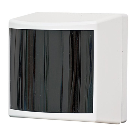
5 Design of the IPDL-Ex
5.1 The principal structural elements of the transmitting module (TM) and the
receiving module (RM) (See Figure 1) are as follows: 1 – base with a positioner
mirror; 2 – case; 3 – optical unit with an adjuster; cover with a light filter (not shown).
5.2 The bases of the TM and the RM have openings for fastening on the place
of installation by means of screws.
5.3 The base of the RM comprises openings for a HL1 LED indicator, entries
for power cables, AL and optical alarm external device OAED.
5.4 The cover is fastened to the base with the help of a latch.
5.5 The TM includes case, PCB and TM optical unit.
5.6 The following elements are installed on the TM PCB:
- a transmitter installed in the focus of the TM optical unit;
- DIP-switch 1, 2 of transmission power level as per Table 3;
Table 3
Distance between the TM and the RM, m
- a terminal block «+U-
- a terminal block and a «TEST
engagement.
5.7 The RM includes:
- case;
- the PCB installed on the base in the focal plate of the RM optical unit ensures
analog and digital signal processing, external circuits switching, provides information
display at OAED;
- the RM optical unit.
5.8 The following elements are installed in the RM circuit board:
- «+Un-
terminal block for power supply connection;
»
- «Al1» and «Al2» terminal blocks for connecting AL1 (Fire) and AL2 (Fault)
alarm loops;
- «+K-
terminal block for connecting an external optical device (ED) in a standby
»
mode or a voltmeter for signal level measurement during adjustment;
- «A
DIP-switch 1 in the ON position changes the RM to an adjustment mode;
»
- «P
DIP-switch 2 determines the polarity of AL2 signal (Fault):
»
1) ON – AL2 normally opened contact;
2) OFF – normally closed AL2 contact;
- operating threshold adjustment is carried out by means of DIP-switches 3, 4
«THRESHOLD
in compliance with Table 4.
»
- RM LED indicator HL1 of RM displays the current status of IPDL-Ex («Norm»,
«Fire», «Fault») and indicates the delivery or non-delivery of a signal in an adjustment
mode;
- HL2 – HL5 LEDs display signal level in an adjustment mode.
Table 4
«THRESHOLD» (% of Signal Strength
Loss as Compared to the Set Level)
20
30
40
50
6 IPDL-Ex Installation
6.1 Safety Rules for Operation of Customers' Electrical Installations and
Customers' Electrical Installations Operation Rules, the recommendations of local
fire department should be observed to in the process of IPDL-Ex installation and
operation.
QNT
6.2 The IPDL-Ex should be installed in closed or semi-closed premises at most
probable smoke accumulation points in case of a fire (above fire hazard locations,
1 pc.
far away from exhaust ventilation and air draughts).
1 pc.
6.3 The bases for the TM and the RM installation should be rigid and should
1 pc.*
have level surfaces (a load-bearing wall or a timber).
6.4 The IPDL-Ex should be installed at the location accessible for maintenance
4 pcs.
in line-of-sight zone on a side of the premise passages.
4 pcs.
6.5 The distance between the TM and the RM must not exceed 150 m, whereupon
1 copy
there should be no overcovering objects in the monitored zone and the possibility
of their emergence should be excluded.
Receiving module
1 – base;
2 – optical unit;
3 – printed circuit board (PCB);
4 – adjustment screw in vertical
plane;
5 – adjustment screw in
horisontal plane;
6 – mirror;
7 – visor.
Transmitting module
Figure 1
RM «P» Switch Arms Positions
150
60
20
for power supply connection;
»
key button intended for self-test mode
»
«THRESHOLD»
Position of
DIP-switch 3
OFF
OFF
ON
ON
1 - ON, 2 - ОFF
1 - ОFF, 2 - ОN
1 - ОFF, 2 - ОFF
«THRESHOLD»
Position of
DIP-switch 4
OFF
ON
OFF
ON
Advertisement

Related Manuals for Rielta IPDL-Ex


Summary of Contents for Rielta IPDL-Ex
- Page 1 » b) 20 mA in «Fault» and «Fire» modes. - RM LED indicator HL1 of RM displays the current status of IPDL-Ex («Norm», 3.10 The IPDL-Ex provides IP41 rating. «Fire», «Fault») and indicates the delivery or non-delivery of a signal in an adjustment 3.11 Dimensions of IPDL-Ex TM and RM –...
- Page 2 - put DIP-switch 1 «A» into the OFF position, whereupon the IPDL-Ex is finishing 6.8 The IPDL-Ex should be installed at 0.3 to 0.6 m distance from ceilings. In case adjustment and assigns the time for installing the cover and fine adjustment with the premise height is greater than 12 m, the IPDL-Ex should be installed in two tiers.
Need help?
Do you have a question about the IPDL-Ex and is the answer not in the manual?
Questions and answers