Table of Contents
Advertisement
Advertisement
Table of Contents

Related Manuals for HIKVISION DS-K1T105 Series


Summary of Contents for HIKVISION DS-K1T105 Series
- Page 1 Access Control Terminal User Manual V1.1.0 UD01651B...
- Page 2 Hikvision marks are the property of Hikvision and are registered trademarks or the subject of applications for the same by Hikvision and/or its affiliates. Other trademarks mentioned in this manual are the properties of their respective owners. No right of license is given to use such trademarks without express permission.
- Page 3 Access Control Terminal·User Manual Regulatory Information FCC Information compliance: This equipment has been tested and found to comply with the limits for a digital device, pursuant to part 15 of the FCC Rules. These limits are designed to provide reasonable protection against harmful interference when the equipment is operated in a commercial environment.
- Page 4 Access Control Terminal·User Manual If smoke, odors or noise rise from the device, turn off the power at once and unplug the power cable, and then please contact the service center. If the product does not work properly, please contact your dealer or the nearest service center. Never attempt to disassemble the device yourself.
-
Page 5: Table Of Contents
1 Overview ................................. 3 1.1 Introduction ................................3 1.2 Main Features ................................3 1.2.1 Main Features of DS-K1T105 Series Model ......................3 1.2.2 Main Features of DS-K1T200 Series Model ......................4 2 Appearance ................................5 2.1 Appearance of DS-K1T105 Series Model ........................5 2.2 Appearance of DS-K1T200Series Model ........................ - Page 6 Access Control Terminal·User Manual 6.5 Upload/Download Settings ............................. 30 6.6 Testing ..................................31 6.7 Log Query Settings ..............................31 6.8 System Information ..............................32 7 Client Operation ..............................33 7.1 Overview of Access Control System ......................... 33 7.1.1 Description................................ 33 7.1.2 Configuration Flow ............................33 7.2 Device Management ...............................
-
Page 7: Overview
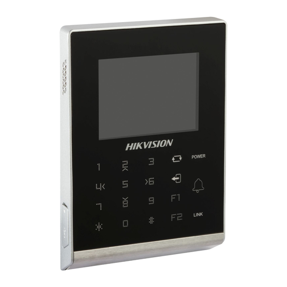
1 Overview 1.1 Introduction Figure 1-1 DS-K1T105 Series Standalone Access Control Terminal Front Panel DS-K1T105 is a series of standalone access control terminal with picture capturing function. DS-K1T105 is designed with a 2.8-inch LCD display screen, and HD camera (2 MP optional). It supports two network communication methods (TCP/IP, and Wi-Fi), and supports offline operation. -
Page 8: Main Features Of Ds-K1T200 Series Model
Access Control Terminal·User Manual Data can be permanently saved after power-off 1.2.2 Main Features of DS-K1T200 Series Model Doorbell ringtone settings function Touch mode and blue light display technique for keypad Stand-alone settings for the terminal ... -
Page 9: Appearance
Access Control Terminal·User Manual 2 Appearance 2.1 Appearance of DS-K1T105 Series Model Please refer to the following content for detailed information of the DS-K1T105 series model. Figure 2-1 Appearance of DS-K1T105 Series Model Table 2-1 Description of DS-K1T105 Series Model Description 2.8-Inch LCD Display Screen... -
Page 10: Appearance Of Keys
Access Control Terminal·User Manual Description HD Camera with 2 MP (only DS-K1T200EF/MF -C support) Keypad Optical Fingerprint Reading Module USB 2.0 Interface Power Interface PSAM Card Slot External Wiring Terminals Serial Port Ethernet Port Tampering Prevention Switch 2.3 Appearance of Keys Figure 2-3 Appearance of Keys 2.3.1 Description of Items Table 2-3 Description of Keys... - Page 11 Access Control Terminal·User Manual Note: In the Event Card Interact interface in the iVMS-4200 Client Software, choose the alarm output of Event Bell. You can connect a bell at the alarm output terminal. For details about configuring the Event Bell alarm output, see the User Manual of iVMS- 4200 Client Software.
-
Page 12: Terminal Connection
Access Control Terminal·User Manual 3 Terminal Connection 3.1 Terminal Description Figure 3-1 Terminal Diagram of Access Control Terminal... - Page 13 Access Control Terminal·User Manual Table 3-1 Terminal Description Terminal Line Group Function Color Description Name +12V 12V DC Power Supply Line Group A Power Input Black Yellow/Blue Alarm Input 1 Alarm Input Yellow/Black Yellow/Orange Alarm Input 2 Line Group B Yellow/Purple Alarm Output Yellow/Brown...
-
Page 14: Wiring Description
Access Control Terminal·User Manual 4 Wiring Description 4.1 External Device Wiring Overview Figure 4-1 External Device Connection Diagram... -
Page 15: The Wiring Of External Card Reader
Access Control Terminal·User Manual 4.2 The Wiring of External Card Reader 4.2.1 The Wiring of External RS-485 Card Reader Figure 4-2 External RS-485 Card Reader Connection Diagram 4.2.2 The Wiring of External Wiegand Card Reader Figure 4-3 External Wiegand Card Reader Connection Diagram Notes: ... -
Page 16: The Wiring Of Electric Lock And Door Contact
Access Control Terminal·User Manual 4.3 The Wiring of Electric Lock and Door Contact 4.3.1 The Wiring of Electric Lock Figure 4-4 The Installation of Electric Dropbolt, Magnetic Lock, and Electric Strike Note: Signal input interface of the door status (DOOR_NC, DOOR_COM, DOOR_NO) is used to recognize whether the door is locked. If the NC interface is connected for opening door, the NO interface can only be connected for locking door. -
Page 17: The Wiring Of Exit Button
Access Control Terminal·User Manual 4.4 The Wiring of Exit Button Figure 4-6 The Installation of Exit Button 4.5 The Wiring of Alarm Input Figure 4-7 Alarm Input Connection... -
Page 18: The Wiring Of External Alarm Device
Access Control Terminal·User Manual 4.6 The Wiring of External Alarm Device Figure 4-8 The Installation Diagram of External Alarm Device 4.7 Card Reader Connection The access control terminal can be switched into the card reader mode. It can access to the access control as a card reader, and supports Wiegand communication port and RS-485 communication port. -
Page 19: The Wiring Of Rs-485 Output
Access Control Terminal·User Manual 4.7.2 The Wiring of RS-485 Output Figure 4-10 RS-485 Connection Diagram Notes: Set the working mode of the terminal as card reader, which can be configured in System Parameter –> Mode Switch, if the terminal requires working as a card reader. ... -
Page 20: Activating The Access Control Terminal
Access Control Terminal·User Manual 5 Activating the Access Control Terminal Purpose: You are required to activate the terminal first before using it. Activation via SADP, and Activation via client software are supported. The default values of the control terminal are as follows. ... -
Page 21: Activating Via Client Software
Access Control Terminal·User Manual Figure 5-2 Modify Network Parameters Interface 6. Input the password and click the Save button to activate your IP address modification. 5.2 Activating via Client Software The client software is versatile video management software for multiple kinds of devices. Get the client software from the supplied disk or the official website, and install the software according to the prompts. - Page 22 Access Control Terminal·User Manual Figure 5-4 Device List Check the device status from the device list, and select an inactive device. Click the Activate button to pop up the Activation interface. Figure 5-5 List Selecting Interface Create a password and input the password in the password field, and confirm the password. STRONG PASSWORD RECOMMENDED–...
-
Page 23: Basic Operation
Access Control Terminal·User Manual 6 Basic Operation Before You Start: You should activate the device before the first login. Otherwise, after powered on, the system will switch into activate notifying interface. For detailed information about activation, see Chapter 5 Activating the Access Control Terminal. Figure 6-1 Activation Notifying Interface ... -
Page 24: User Management
Access Control Terminal·User Manual Figure 6-3 Password Authentication Interface Enter the default configuration password. Tap the # key to confirm the settings. If the configuration password authentication failed, the system will return to the initial interface, and if the configuration password is successfully authenticated, the system will enter the menu operation interface Figure 6-4 Menu Operation Interface On the menu operation interface, you can manage users, set communication parameters, set system parameters, and so on. -
Page 25: Managing User
Access Control Terminal·User Manual Figure 6-6 Card Registration Interface Register the card. Register the card by swiping the card. 1) Place the card on the induction area. 2) The system displays the card No. in the textbox automatically with a beep sound if the card No. has been recognized. . ... - Page 26 Access Control Terminal·User Manual Searching User Steps: Move the cursor to a user by using direction keys. Tap the # key to pop up an interface for selecting corresponding operations. Figure 6-9 Managing User Interface Move the cursor to Search User. Tap the # key to enter the searching interface.
-
Page 27: Communication Settings
Access Control Terminal·User Manual Move the cursor to Add to enter the fingerprint registration interface. See details in step 4 of adding user. Note: DS-K1T105 series model does not support this function. Changing the Password Move the cursor to Change PWD to enter the password changing interface. -
Page 28: Network Settings
Access Control Terminal·User Manual Figure 6-13 Communication Settings Interface Network Settings: It refers to network parameters of the device, including IP address, subnet mask, and gateway address. Serial Port Settings: When the access control terminal works as a RS-485 card reader, serial port parameters include working mode, Baud Rate, and RS-485 address. -
Page 29: Wiegand Settings
Access Control Terminal·User Manual Figure 6-15 Serial Port Settings Interface Modify parameters of the serial port, including working mode, Baud Rate, and RS-485 address. Working Mode: When the access control terminal works as the terminal, you can connect it to Card Reader, Client Software and Control Unit. -
Page 30: Wi-Fi Settings
Access Control Terminal·User Manual Move the cursor to the OK button, and tap the # key. Note: Reboot the device after changing the Direction. 6.2.4 Wi-Fi Settings Steps: Move the cursor to Wi-Fi (Wi-Fi settings) by using direction keys on the communication settings interface. Tap the # key to enter the Wi-Fi settings interface. -
Page 31: Setting System
Access Control Terminal·User Manual Steps: Move the cursor to System (system parameters) by using direction keys. Tap the # key to enter the system parameters interface. Figure 6-20 System Settings Interface System Parameters: System parameters of the device include the device running mode, login password, and prompt sound. Data Management: It is used to manage the storage data of the device, including Delete Card Parameters, Delete Event Only, and Delete Picture Only. -
Page 32: Managing Data
Access Control Terminal·User Manual Notes: Tap the key to enter and exit the editing mode. Tap the Right/Left direction keys to choose contents. Tap the # key to switch the mode between “Yes” mode and “No” mode. Move the cursor to the OK button, and tap the # key. -
Page 33: Door Settings
Access Control Terminal·User Manual 6.3.4 Door Settings Purpose: On the door settings interface, you can set door parameters, including Controller Authentication, Card Reader Authentication, Door Action Time, Delayed Door Alarm, and Anti-passing Back. Steps: Move the cursor to ACS(door settings) by using direction keys in the system settings interface. Tap the # key to enter the door settings interface. -
Page 34: Time Settings
Access Control Terminal·User Manual Display Picture: When enabling to display the picture, captured pictures can display on the screen. Notes: Tap the key to enter and exit the editing mode. Tap the Right/Left direction keys to choose contents. ... -
Page 35: Testing
Access Control Terminal·User Manual Move the cursor to Device Upgrade, Upload Access Settings, Download Access Settings, Download Attendance Record, or Download Captured Picture. Device Upgrade: The system can automatically read the upgrading information from the USB, and upgrade the device. Note: The upgrading file should be put in the root directory. -
Page 36: System Information
The default maximum fingerprint amounts of devices with fingerprint registering function are as follows. Optical device: 9500 DS-K1T105 series model does not support this function. Device Information In the device information interface, you can view the device name, the serial No., Mac address, and so on. -
Page 37: Client Operation
Access Control Terminal·User Manual 7 Client Operation 7.1 Overview of Access Control System 7.1.1 Description The access control system is a system of configuring permission of door access. It provides multiple functionalities, including access controller management, people/card management, permission configuration, door status management, event search, etc. This user manual describes the function, configuration and operation steps of Access Control System. -
Page 38: Device Management
Access Control Terminal·User Manual 7.2 Device Management 7.2.1 Controller Management Interface Introduction Click the icon to enter the controller management interface. The interface is divided into 2 parts: device management and online device detection. Device Management: Manage the access control devices, including adding, editing, deleting, and batch time synchronizing functions. Online Device Detection: Automatically detect online devices in the same subnet with the access control server, and the detected devices can be added to the server in an easy way. - Page 39 Access Control Terminal·User Manual Input the device name. Select the access controller type in the dropdown list. Select the connection mode in the dropdown list: TCP/IP, or COM port, or Ehome. TCP/IP: Connect the device via the network. Ehome: Connect the device via the Ehome protocol. Set the parameters of connecting the device.
- Page 40 Access Control Terminal·User Manual Steps: In the editing interface, click the Door_1 button to edit the information of the selected door. Door Contact: The Door Contact is in the status of Remain Closed (excluding special conditions). Exit Button Type: The Exit Button Type is in the status of Remain Open (excluding special conditions). Door Locked Time(s): After swiping the normal card and relay action, the timer for locking the door starts working.
- Page 41 Access Control Terminal·User Manual Click the Edit button to save parameters. Click the Hardware Parameters Downloading button to download the updated parameters to the local memory of the device. Deleting Device Steps: In the device list, select a device by clicking it, or select multiple devices by pressing Ctrl button on your keyboard and clicking them one by one.
- Page 42 Access Control Terminal·User Manual Network Settings Purpose: In the network settings interface, the network settings of the device can be uploaded and reported. Uploading Mode Settings Steps: In the access controller editing interface, click Network Settings button to enter the network settings interface. Click the Uploading Mode Settings button.
- Page 43 Access Control Terminal·User Manual Steps: In the access controller editing interface, click Network Settings button to enter the network settings interface. Click the Network Center Settings button. Select the network center in the dropdown list. Select the address type in the dropdown list: IP, or Domain Name. IP: Input the IP address, and port No..
- Page 44 Access Control Terminal·User Manual Steps: In the Edit Access Controller interface, click the RS-485 Settings button to enter the RS-485 Settings interface. Select the RS-485 channel, the bitrate, the data bit, the stop bit, the parity, the flow control, the communication mode, the work mode and the connect type in the dropdown list.
-
Page 45: Access Control Point Management
Access Control Terminal·User Manual 7.2.2 Access Control Point Management Interface Introduction Click the icon on the control panel to enter the door management interface. Group Management The doors can be added to different groups to realize the centralized management. Door Management Manage the specific door under the door group, including importing, editing and deleting door. -
Page 46: Permission Management
Access Control Terminal·User Manual And then click the OK button in the popup window. Access Control Point Management Access control points under the group can also be edited, refer to the following instructions. Importing Access Control Point Steps: Click the button to pop up the access control point importing interface. - Page 47 Access Control Terminal·User Manual Department Management Steps: In the department list, click button to pop up the adding department interface. Notes: Multi-level department system can be created. Click a department as the upper-level department and click button, and then the added department will be the sub-department of it. ...
- Page 48 Access Control Terminal·User Manual Optionally, you can Click Fingerprint to enter the fingerprint adding interface. Click the Start Register button, and select the fingerprint to scan. Click the Save button to save the parameter. Or click the Delete Fingerprint button to delete the scaned fingerprint. Or click the Delete All button to clear all scaned fingerprints.
- Page 49 Access Control Terminal·User Manual Click OK in the pop-up window to delete. Note: The card information associated with the person will also be deleted. Editing Person Steps: Double-click the person name in the person list. Or select a person in the person list and click the Edit button to enter the edit interface. Editing the Person Name (required), Gender, ID Card, etc., upload the photo of the person and click the icon to finish editing.
- Page 50 Access Control Terminal·User Manual Importing Person Purpose: Import the person information in the device to the client software. Steps: In the Person Management interface, select a department. Click Import. Select a device in the device select interface and click OK. Click the button when the import is completed.
-
Page 51: Card Management
Access Control Terminal·User Manual Click the button again to complete importing. The person information will be added in the person list. 7.3.2 Card Management Interface Introduction Click on the control panel of the software to enter the card management interface. The cards are divided into 3 types: Blank Card, Normal Card, and Lost Card. - Page 52 Access Control Terminal·User Manual Batch Adding Cards Choose the Bulking Adding as the adding mode by clicking the and input the activation date, expiry date, start card No. and last card No. in the corresponding text fields. Note: The start card No. and the last card No. should be in the same length. E.g., the last card No. is 234, then the start card No. should be like 028.
- Page 53 Access Control Terminal·User Manual Click to choose a person on your demand in the popup dialog box, select a fingerprint, and click to finish. Notes: • The issued card will disappear from the Blank Card list, you can check the card information in the Normal Card list. •...
-
Page 54: Schedule Template
Access Control Terminal·User Manual Note: The password will be required when the card holder swiping the card to enter to or exit from the door if you enable the card & password authentication on the advanced configuration page. Lost Card Click the tab in the card management interface to show the Lost Card list. - Page 55 Access Control Terminal·User Manual 2. Input the name of week plan and click the OK button to add the week plan. 3. Select a week plan in the plan list on the left-side of the window to edit. 4. Click and drag your mouse on a day to draw a blue bar on the schedule, which means in that period of time, the configured permission is activated.
- Page 56 Access Control Terminal·User Manual Click to select a configured duration and click the to delete it. Click the to clear all the configured durations, while the holiday still exists. Click the to delete the holiday directly. Click the button to save the settings. Note: The holidays cannot be overlapped with each other.
-
Page 57: Door Status Management
Access Control Terminal·User Manual Click to select a holiday group in the left-side list and click the to add it. Click to select an added holiday group in the right-side list and click the to delete it. Click the to delete all the added holiday groups. - Page 58 Access Control Terminal·User Manual Click and drag the mouse to draw a color bar on the schedule map to set the duration. Notes: The min. segment of the schedule is 30 mins. You can copy the configured time periods of a day to the whole week. Steps: Select a day which has already been configured.
-
Page 59: Interact Configuration
Access Control Terminal·User Manual Click on to enter the Download Door State page. Select a control point and click OK to download the settings to the system. 7.3.5 Interact Configuration Click on the control panel of the software to enter the interact configuration interface. - Page 60 Access Control Terminal·User Manual In this interface, you can set alarm linkage modes of the access host, including case trigger, event card interact, and client interact. Case Trigger Purpose: The case (refer to the triggers of the controller) can be linked to some actions (e.g., alarm output, host buzzer) when it is triggered. Steps: Click the button to enter the case trigger interface, and select a case.
- Page 61 Access Control Terminal·User Manual Click the button to enter the event card interface Select the host to be set from the host list. Click the button to start setting the event linkage. Click the radio button of the event linkage, and select the event type from the dropdown list. Set the linkage target, and set the property as Trigger to enable this function.
-
Page 62: Access Permission Configuration
Access Control Terminal·User Manual Reader Buzzer: The audible warning of card reader will be triggered. Alarm Output: The alarm output will be triggered for notification. Door: The door status of open, close, normally open, and normally close will be triggered. Click the button to save parameters. - Page 63 Access Control Terminal·User Manual Click on the dropdown menu to select a schedule template for the permission. Note: The schedule template must be configured before any permission settings. Refer to Section 7.3.3 Schedule Template for detailed configuration guide. Select people/ department and corresponding doors/door groups from the appropriate lists. Note: The lower-level of department will also be selected if the highest-level of department is selected, Click the Done button to complete the permission adding.
- Page 64 Access Control Terminal·User Manual Select a control point and click the OK button, to enter the download result interface, to download the permission to the device. Access Permission Searching Purpose: After the permission settings being completed, you can search and view permission assigning condition on the searching interface. Steps: Enter the Permission page.
-
Page 65: Attendance Management
Access Control Terminal·User Manual Note: You can click Reset on the search criteria panel to clear all the displayed search results. Permission Deleting Steps: Follow steps 1-3 in the Permission Searching section to search for the permission needs to be deleted. Select the permission from the results list. - Page 66 Access Control Terminal·User Manual Click the icon on the control panel to enter the interface. Shift Group Management Purpose: On the shift group management interface, you can add, edit, and delete shift groups for attendance management. Steps: Click the button to pop up the shift group formation window. Enter the shift group name, and click the button on the person list area to pop up the person adding window.
- Page 67 Access Control Terminal·User Manual Check the checkbox(es) of persons to be added and click the button and return to the shift group settings interface. Note: To delete the added person, check the person from the person list, and click the button.
- Page 68 Access Control Terminal·User Manual Note: You can edit and delete the added shift groups by clicking the buttons. Shift Management Press the Shift Management tab to enter the shift management interface. There are two kinds of shifts in this interface: Normal Shift, and Man-Hour Shift. Normal Shift ...
- Page 69 Access Control Terminal·User Manual Set a rule name. Set detailed parameters for the attendance rule: on-work attendance check advance time, on-work late time, absence threshold, break time, off-work attendance check delay time, off-work early time, and absence threshold (early leave). Click the button to complete the operation.
- Page 70 Access Control Terminal·User Manual Set a shift name, and daily working duration. (Optional) Check the checkbox of latest on-work time, and set the latest on-work time. (Optional) Set the disregard man-hour period. Click the button to complete the operation. Holiday Management Press the Holiday Management tab to enter the holiday management interface.
- Page 71 Access Control Terminal·User Manual Click the button to pop-up holiday adding window. Set the start date and end date, select the date of week, and click the button. Shift Schedule Management Press the Shift Schedule Management tab to enter the shift schedule management interface. Steps: Press a tab of shift group on the shift group list.
- Page 72 Access Control Terminal·User Manual Select the shift name from the drop-down list. Set the start data and end data. (Optional) Check the checkbox of holiday to add the holiday shift. Click the button to complete the operation. Attendance Check Point Management Press the Attendance Check Point Management tab to enter the attendance check point management interface.
- Page 73 Access Control Terminal·User Manual window. Edit the attendance checking point name, start date, validity, and attendance checking point type, controller name, door position, and reader name. Click the button to complete the operation. Adding Attendance Check Point Check the checkbox of a checking point and click the button to delete the added checking point.
- Page 74 Access Control Terminal·User Manual Enter the adjustment reason, and click the button. Notes: • The default adjustment reasons include leave for personal affairs, sick leave, marriage leave, funeral leave, home leave, annual leave, maternity leave, and paternity leave. • You can check the checkbox of a reason and click the button to edit the reason, and click the button to delete the reason.
- Page 75 Access Control Terminal·User Manual • You can check the checkbox of a reason and click the button to edit the reason, and click the button to delete the reason. Overtime Steps: Press the overtime tab to enter the overtime interface. Click the button to pop up the adjustment reason adding dialog box.
- Page 76 Access Control Terminal·User Manual Click the button to pop up the adjustment reason adding dialog box. Enter the adjustment reason, and click the button. Notes: • The default adjustment reasons for card replacing include forget to swipe card, attendance card lost, device fault, shift adjustment, and business trip.
- Page 77 Access Control Terminal·User Manual Click the button. Select the radio button of adjustment type: leave, leave in lieu, overtime, and replace card. Leave, Leave in Lieu, and Overtime Select the adjustment reason from the drop-down list. Click the button to pop up the person adding window. Select the person and click the button.
- Page 78 Access Control Terminal·User Manual Select the adjustment reason from the drop-down list. Click the button to pop up the person adding window. Select the person and click the button. Set the date, attendance shift, and card replacing time. Click the button to complete the operation ...
- Page 79 Access Control Terminal·User Manual Click the button to disable the information. Press the Disabled tab and the disabled information will be listed on the disabled interface. Card Swiping Log Query Press the Card Swiping Log Query tab to enter the card swiping log searching and viewing interface. Notes: •...
- Page 80 Access Control Terminal·User Manual On the statistic analysis interface, you can search the attendance analysis table, attendance result statistic table, and attendance rate statistic table. Attendance Analysis Table Press the Attendance Analysis Table tab to enter the attendance analysis interface. Notes: •...
- Page 81 Access Control Terminal·User Manual Notes: • You can search the attendance result statistics by different shift type: Normal Shift, or Man-Hour Shift. • You can search the attendance result statistics by department. • You can search the attendance result statistics by start date and end date. Attendance Rate Statistic Table Press the Attendance Rate Statistic Table tab to enter the attendance rate analysis interface.
-
Page 82: Advanced Functions
Access Control Terminal·User Manual Click the button to calculate the attendance date. On this interface, you can export and import attendance data. 7.3.8 Advanced Functions Purpose: The advanced functions of the access control system can be configured, such as access control type, password authentication and first card. - Page 83 Access Control Terminal·User Manual Duress Card: The card swiping action will be uploaded. Super Card: The card is valid for all the doors of the controller during the configured schedule. Visitor Card: The card is assigned for visitors. Click Add and select the available card. Click OK to confirm assigning the card(s) to the selected card type.
- Page 84 Access Control Terminal·User Manual Steps: Click Multiple Authentication tab and select a group in the access controller from the list on the left. Edit the role name, the card swiping times and the expiry date. And click Add to add the group members. Check the target members and click Add to add the selected members.
- Page 85 Access Control Terminal·User Manual Click Add at the bottom to add the configured the authentication group to the group list. And click Save to save the configuration. Note: Click Apply on the upper-left to take effect of the new settings. First Card Purpose: The door remains open for the configured time duration after the first card swiping.
- Page 86 Access Control Terminal·User Manual You can set the name for the controller and select the card reader as the beginning of the path. In the list, click the text filed of Card Reader Afterward and select the linked card readers. Example: If you select Reader In_01 as the beginning, and select Reader In_02, Reader Out_04 as the linked card readers.
- Page 87 Access Control Terminal·User Manual Select the access control point (door) from the list. Note: Up to four doors can be added in one multi-door interlocking combination. Click OK to save the adding. (Optional) After adding the multi-door interlocking combination, you can select it from the list and click Delete to delete the combination.
- Page 88 Access Control Terminal·User Manual Instruction Digit Description Format Content Command 010-Open, 011-Closed, 020-Normally open, 021-Normally Closed, 120-Disarm, 121-Arm Operation Range 1-all objects with Command#1# permission, 2-single operation Operation Object Starts from 1 Command#2#Operation (corresponding to different Object# doors or arming regions according to commands) Password Authentication Purpose:...
-
Page 89: Checking Status And Event
Access Control Terminal·User Manual Click the Ok button to finish adding the card. Notes: The card, having added the password, will display in the card list. You can select the card in the card list, and click the Delete button to delete the password authentication of the selected card. -
Page 90: Access Control Event
Access Control Terminal·User Manual You can also right click the icon and to select a status for the door. Notes: If the status is selected as Remain Open/Remain Closed, the door will keep open/ closed until a new anti-control command being made. -
Page 91: Event Search
Access Control Terminal·User Manual Click the icon on the control panel to enter the interface. Steps: Enter the access event page. View the event information in the event list. Click on an event to view the information of the card holder on the Person Information panel on the left side of the page. 7.4.3 Event Search Purpose: You can search historical access event according to the search criteria (such as event type, name of the person, card No. - Page 92 Access Control Terminal·User Manual Click Search to get the search results. View the event information in the event list. Click on an event to view the information of the card holder on the Person Information panel on the left side of the page.
-
Page 93: System Maintenance
Access Control Terminal·User Manual 7.5 System Maintenance 7.5.1 Log Management Interface Introduction Purpose: The log files of the Access Control System and the devices that connected to the Access Control System can be searched for checking. Click the icon on the control panel to open the Log Search page. Configuration Logs Searching Purpose: The Configuration Log files of the Access Control System can be searched by time, including One-Card Configuration, Access Control... - Page 94 Access Control Terminal·User Manual The One-card Configuration Log files include departments, persons and cards log files. One-card Configuration of the Access Control System can be operated as adding, modifying and deleting logs. Steps: Open the Log Search page. Select the radio button of Configuration Logs. Select the operation type as One-card Configuration.
-
Page 95: System Configuration
Access Control Terminal·User Manual Select the operation type as Access Control Logs. Click the icon to specify the start time and end time. Click Search. The matched log files will display on the list. You can check the operation time, log type and other information of the logs. Note: Please narrow the search condition if there are too many log files. - Page 96 Access Control Terminal·User Manual The fingerprint associated functions are only supported by device with fingerprint recognition module Manual Capture Configuration The Manual Capture Configuration is for Access Control system to take photos remotely. Auto Time Synchronization Steps: Open the System Configuration page. Click the Common tab to enter the Common Settings interface.
- Page 97 Access Control Terminal·User Manual Select the device type, serial port number, baud rate, device code, and overtime parameters of the fingerprint machine. Click the save button to save the settings. Notes: It is supported using device type as DS-K1F800-F, DS-K1F810-FOptical Fingerprint Collecting Instrument and DS-K1300-F Capacitive Fingerprint Collecting Instrument.
-
Page 98: Appendix: Tips For Scanning Fingerprint
Access Control Terminal·User Manual Appendix: Tips for Scanning Fingerprint Recommended Finger Forefinger, middle finger or the third finger. Correct Scanning The figure displayed below is the correct way to scan your finger: You should press your finger on the scanner horizontally. The center of your scanned finger should align with the scanner center. Incorrect Scanning The figures of scanning fingerprint displayed below are wrong: Vertical... - Page 99 Access Control Terminal·User Manual...
Need help?
Do you have a question about the DS-K1T105 Series and is the answer not in the manual?
Questions and answers