Table of Contents
Advertisement
Advertisement
Table of Contents

Related Manuals for HIKVISION DS-K1T105E-C


Summary of Contents for HIKVISION DS-K1T105E-C
- Page 1 Access Control Terminal Quick Start Guide UD.6L0206D1079A01...
- Page 2 Trademarks and other Hikvision marks are the property of Hikvision and are registered trademarks or the subject of applications for the same by Hikvision and/or its affiliates. Other trademarks mentioned in this manual are the properties of their respective owners. No right of license is given to use such trademarks without express permission.
- Page 3 FOR LOSS OF BUSINESS PROFITS, BUSINESS INTERRUPTION, SECURITY BREACHES, OR LOSS OF DATA OR DOCUMENTATION, IN CONNECTION WITH THE USE OF OR RELIANCE ON THIS MANUAL, EVEN IF HIKVISION HAS BEEN ADVISED OF THE POSSIBILITY OF SUCH DAMAGES. SOME JURISDICTIONS DO NOT ALLOW THE EXCLUSION OR LIMITATION OF LIABILITY OR CERTAIN DAMAGES, SO SOME OR ALL OF THE ABOVE EXCLUSIONS OR LIMITATIONS MAY NOT APPLY TO YOU.
- Page 4 Access Control Terminal·Quick Start Guide Regulatory Information FCC Compliance This equipment has been tested and found to comply with the limits for a Class B digital device, pursuant to part 15 of the FCC Rules. These limits are designed to provide reasonable protection against harmful interference in a residential installation.
- Page 5 Access Control Terminal·Quick Start Guide 2006/66/EC (battery directive): This product contains a battery that cannot be disposed of as unsorted municipal waste in the European Union. See the product documentation for specific battery information. The battery is marked with this symbol, which may include lettering to indicate cadmium (Cd), lead (Pb), or mercury (Hg).
- Page 6 Access Control Terminal·Quick Start Guide assume any responsibility for problems caused by unauthorized repair or maintenance.) Cautions Do not drop the device or subject it to physical shock, and do not expose it to high electromagnetism radiation. Avoid the equipment installation on vibrations surface or places subject to shock (ignorance can cause equipment damage).
-
Page 7: Table Of Contents
Access Control Terminal·Quick Start Guide Table of Contents 1 Overview ...................... 1 1.1 Introduction ......................1 1.2 Main Features ......................2 1.2.1 Main Features of DS-K1T105 Series Model ............2 1.2.2 Main Features of DS-K1T200 Series Model ............2 2 Appearance ....................4 2.1 Appearance of DS-KITI05 Series Model .............. - Page 8 Access Control Terminal·Quick Start Guide 6.2.4 Wi-Fi Settings ....................37 6.3 System Settings ...................... 38 6.3.1 Setting System ....................39 6.3.2 Managing Data ....................40 6.3.3 Restoring Settings ................... 41 6.3.4 Door Settings ....................41 6.3.5 Setting the Camera ..................42 6.4 Time Settings ......................
-
Page 9: Overview
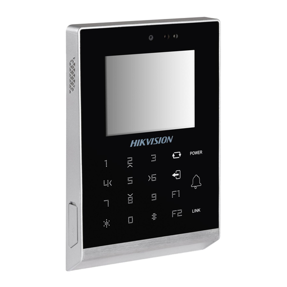
Access Control Terminal·Quick Start Guide 1 Overview 1.1 Introduction Figure 1-1 DS-K1T105 Series Standalone Access Control Terminal Front Panel DS-K1T105 is a series of standalone access control terminal with picture capturing function. DS-K1T105 is designed with a 2.8-inch LCD display screen, and HD camera (2 MP optional). -
Page 10: Main Features
Access Control Terminal·Quick Start Guide with a 2.8-inch LCD display screen, and HD camera (2 MP optional). It is equipped with optical fingerprint recognition module (supporting 1:1 mode and 1:N mode), and supports offline operation. 1.2 Main Features 1.2.1 Main Features of DS-K1T105 Series Model ... - Page 11 Access Control Terminal·Quick Start Guide Touch mode and blue light display technique for keypad. Stand-alone settings for the terminal. 2.8-inch LCD display screen. Transmission modes of wired network (TCP/TP) and Wi-Fi. Face detection and picture capturing function implemented by built-in camera (2 MP optional, only supports DS-K1T200EF/MF-C) ...
-
Page 12: Appearance
Access Control Terminal·Quick Start Guide 2 Appearance 2.1 Appearance of DS-KITI05 Series Model Please refer to the following content for detailed information of the DS-K1T105 series model. Figure 2-1 Appearance of DS-K1T105 Series Model Table 2-1 Description of DS-K1T105 Series Model Description 2.8-Inch LCD Display Screen HD Camera with 2 MP (only DS-K1T105E/M/ -C... -
Page 13: Appearance Of Ds-Kit200Series Model
Access Control Terminal·Quick Start Guide 2.2 Appearance of DS-KIT200Series Model Please refer to the following content for detailed information of DS-K1T200 series model Figure 2-2 Appearance of DS-K1T200 IP-Based Fingerprint Access Control Terminal 2.2.1 Description of Components Table 2-2 DS-K1T200 IP-Based Fingerprint Access Control Terminal Components Description 2.8-Inch LCD Display Screen... -
Page 14: Appearance Of Keys
Access Control Terminal·Quick Start Guide Description Ethernet Port 2.3 Appearance of Keys Figure 2-3 Appearance of Keys 2.3.1 Description of Items Table 2-3 Description of Keys Description Numeric Keys: Enter number in the textbox. Direction Keys: Select icons in the menu. Editing Key: Click the key to enter/exit the editing status. - Page 15 Access Control Terminal·Quick Start Guide Description Illegal Card Illegal Card: Solid Red Off: Network or Wi-Fi Disconnected. Solid Blue: Network or Wi-Fi connected, but client unarmed. Connection Flicker Blue: Network or Status Wi-Fi connected, but client armed. (RS485 Card Reader Mode) Flicker Red: Connection Exception.
-
Page 16: Terminal Connection
Access Control Terminal·Quick Start Guide 3 Terminal Connection 3.1 Terminal Description Figure 3-1 Terminal Diagram of Access Control Terminal... - Page 17 Access Control Terminal·Quick Start Guide Table 3-1 Terminal Description Line Termina Function Color Description Group l Name 12V DC Power +12V Line Supply Power Group Input Black Yellow/Blue Alarm Input 1 Alarm Yellow/Black Input Line Yellow/Orange Alarm Input 2 Group Yellow/Purple Alarm Alarm Output...
- Page 18 Access Control Terminal·Quick Start Guide Line Termina Function Color Description Group l Name Error Prompt LED Orange LED-ERR Indicator Wiring Purple BEEP Beep Siren Wiring Tampering Alarm Grey TAMPER Wiring +12V Power Output Power Output Black White/Purple Line Group White/ Yellow Lock Wiring Door Lock...
- Page 19 Access Control Terminal·Quick Start Guide Line Termina Function Color Description Group l Name Yellow/Grey BUTTON Exit Door Wiring...
-
Page 20: Wiring Description
Access Control Terminal·Quick Start Guide 4 Wiring Description 4.1 External Device Wiring Overview Figure 4-1 External Device Connection Diagram... -
Page 21: The Wiring Of External Card Reader
Access Control Terminal·Quick Start Guide 4.2 The Wiring of External Card Reader 4.2.1 The Wiring of External RS485 Card Reader Figure 4-2 External RS485 Card Reader Connection Diagram When connected to the external card reader, the terminal only supports RS485 communication method (External Wiegand card reader is not supported). -
Page 22: The Wiring Of Electric Lock And Door Magnetic
Access Control Terminal·Quick Start Guide 4.3 The Wiring of Electric Lock and Door Magnetic 4.3.1 The Wiring of Electric Lock Figure 4-3 The Installation of Electric Dropbolt, Magnetic Lock, and Electric Strike... -
Page 23: The Wiring Of Door Contact
Access Control Terminal·Quick Start Guide Signal input interface of the door status (DOOR_NC, DOOR_COM, DOOR_NO) is used to recognize whether the door is locked. If the NC interface is connected for opening door, the NO interface can only be connected for locking door. 4.3.2 The Wiring of Door Contact Figure 4-4 The Installation of Door Contact... -
Page 24: The Wiring Of Exit Button
Access Control Terminal·Quick Start Guide 4.4 The Wiring of Exit Button Figure 4-5 The Installation of Exit Button... -
Page 25: The Wiring Of Alarm Input
Access Control Terminal·Quick Start Guide 4.5 The wiring of Alarm Input Figure 4-6 Alarm Input Connection 4.6 The Wiring of External Alarm Device Figure 4-7 The Installation Diagram of External Alarm Device... -
Page 26: Card Reader Connection
Access Control Terminal·Quick Start Guide 4.7 Card Reader Connection The access control terminal can be switched into the card reader mode. It can access to the access control as a card reader, and supports Wiegand communication port and RS485 communication port. When the access control terminal works as a card reader, it only supports being connected to the controller, but does not support alarm input or output, or the connection of external devices. -
Page 27: The Wiring Of Rs485 Output
Access Control Terminal·Quick Start Guide When the access control terminal works as a card reader, you must connect the LED-ERR and BEEP interfaces if you want to control the LED and buzzer of the Wiegand card reader. Set the working mode of the terminal as card reader, which can be configured in System Parameter –>... - Page 28 Access Control Terminal·Quick Start Guide Set the working mode of the terminal as card reader, which can be configured in System Parameter –> Mode Switch, if the terminal requires working as a card reader. When the access control terminal works as a RS485 card reader, the default RS485 address is 1.
-
Page 29: Activating The Access Control Terminal
Access Control Terminal·Quick Start Guide 5 Activating the Access Control Terminal Purpose: You are required to activate the terminal first before using it. Activation via SADP, and Activation via client software are supported. The default values of the control terminal are as follows. ... - Page 30 Access Control Terminal·Quick Start Guide Figure 5-1 SADP Interface Create a password and input the password in the password field, and confirm the password. STRONG PASSWORD RECOMMENDED– We highly recommend you create a strong password of your own choosing (using a minimum of 8 characters, including upper case letters, lower case letters, numbers, and special characters) in order to increase the security of your product.
-
Page 31: Activating Via Client Software
Access Control Terminal·Quick Start Guide Figure 5-2 Modify Network Parameters Interface 6. Input the password and click the Save button to activate your IP address modification. 5.2 Activating via Client Software The client software is versatile video management software for multiple kinds of devices. - Page 32 Access Control Terminal·Quick Start Guide Figure 5-3 Control Panel Interface Click the Controller Management icon to enter the Controller Management interface, as shown in the figure below. Figure 5-4 Device List Check the device status from the device list, and select an inactive...
- Page 33 Access Control Terminal·Quick Start Guide device. Click the Activate button to pop up the Activation interface. Figure 5-5 List Selecting Interface Create a password and input the password in the password field, and confirm the password.
- Page 34 Access Control Terminal·Quick Start Guide STRONG PASSWORD RECOMMENDED– We highly recommend you create a strong password of your own choosing (using a minimum of 8 characters, including upper case letters, lower case letters, numbers, and special characters) in order to increase the security of your product. And we recommend you reset your password regularly, especially in the high security system, resetting the password monthly or weekly can better protect your product.
-
Page 35: Basic Operation
Access Control Terminal·Quick Start Guide 6 Basic Operation Before You Start: You should activate the device before the first login. Otherwise, after powered on, the system will switch into activaon notifying interface. For detailed information about activation, see Chapter 5. Figure 6-1 Activation Notifying Interface ... -
Page 36: User Management
Access Control Terminal·Quick Start Guide Figure 6-3 Password Authentication Interface Enter the default configuration password. Click the # key to confirm the settings. If the configuration password authentication failed, the system will return to the initial interface, and if the configuration password is successfully authenticated, the system will enter the menu operation interface Figure 6-4 Menu Operation Interface... -
Page 37: Adding User
Access Control Terminal·Quick Start Guide Figure 6-5 User Management Interface 6.1.2 Adding User Purpose: In the Adding User menu, you can add users, register card, and record fingerprints optionally for the corresponding person. Steps: Move the cursor to Add (add user) by using the direction keys. Click the # key to enter the card registration interface. - Page 38 Access Control Terminal·Quick Start Guide 1) Click the key to enter the editing mode. 2) Enter the card number into the textbox. 3) Click the key to exit the editing mode. After registering the card, a dialog box about whether to register the fingerprint pops up.
-
Page 39: Managing User
Access Control Terminal·Quick Start Guide 6.1.2 Managing User Move the cursor to Manage (edit user) by using direction keys on the user management interface. Click the # key to enter the managing user interface. Searching User Steps: Move the cursor to a user by using direction keys. Click the # key to pop up an interface for selecting corresponding operations. - Page 40 Access Control Terminal·Quick Start Guide Editing User Steps: Move the cursor to a user by using direction keys. Click the # key to popup an interface for selecting corresponding operations. (Figure 6-9) Move the cursor to Editing User. Click the # key to enter the editing interface. Figure 6-11 Editing Interface Edit the user information.
- Page 41 Access Control Terminal·Quick Start Guide Figure 6-12 Password Changing Interface Changing the valid date You can set the start/end time of the user’s permission. Click the key to enter/exit the editing mode. Enabling first card Click the # key to enable first card. After enabling first card, the door remains open during the pre-defined valid duration.
-
Page 42: Communication Settings
Access Control Terminal·Quick Start Guide 6.2 Communication Settings Purpose: On the communication settings interface, you can set network parameters, the serial port, Wiegand parameters, and Wi-Fi. Steps: Move the cursor to Comm (communication settings) by using direction keys. Click the # key to enter the communication settings interface. Figure 6-13 Communication Settings Interface Network Settings: It refers to network parameters of the device, including IP address, subnet mask, and gateway address. -
Page 43: Serial Port Settings
Access Control Terminal·Quick Start Guide Figure 6-14 Network Settings Interface Modify network parameters of the device, including IP address, subnet mask, and gateway address. Click the key to enter/exit the editing mode. Move the cursor to the OK button, and click the # key. 6.2.2 Serial Port Settings Purpose: When the access control terminal works as the RS485 card reader, you should set serial... -
Page 44: Wiegand Settings
Access Control Terminal·Quick Start Guide Modify parameters of the serial port, including working mode, Baud Rate, and RS485 address. Working Mode: Up serial port and down serial port are supported. Set the working mode of the serial port as Down (downstream) if the access control terminal is connected to the external card reader. -
Page 45: Wi-Fi Settings
Access Control Terminal·Quick Start Guide Enable the Wiegand: Select whether to enable the Wiegand. Click the # key to enable first card. Wiegand Mode: The default Wiegand mode is Wigand 34. Click the key to enter and exit the editing mode. ... -
Page 46: System Settings
Access Control Terminal·Quick Start Guide Figure 6-18 Wi-Fi Selection Move the cursor to a network, and click # key to enter the network connection interface. Figure 6-19 Wi-Fi Settings Enter the password of the network. Edit the IP mode, IP address, subnet mask, and gateway address. Move the cursor to the OK button, and click the # key. -
Page 47: Setting System
Access Control Terminal·Quick Start Guide Click the # key to enter the system parameters interface. Figure 6-20 System Settings Interface System Parameters: System parameters of the device include the device running mode, login password, and prompt sound. Data Management: It is used to manage the storage data of the device, including Delete Card Parameters, Delete Event Only, and Delete Picture Only. -
Page 48: Managing Data
Access Control Terminal·Quick Start Guide Modify system parameters, including switching the mode, entering the login password, and enabling voice prompts. Mode: The device mode can be switched between Controller and Card Reader. After switching the mode, the system can automatically reboot and enter into the interface of the new mode. -
Page 49: Restoring Settings
Access Control Terminal·Quick Start Guide Move the cursor to Delete Card Parameters, Delete Event Only, or Delete Picture Only. Delete Card Parameters: Delete all cards parameters registered in the device. Delete Event Only: Delete all access events in the system. Delete Picture Only: Delete all captured pictures in the system. -
Page 50: Setting The Camera
Access Control Terminal·Quick Start Guide On the door settings interface, you can set door parameters, including Controller Authentication, Card Reader Authentication, Door Action Time, Delayed Door Alarm, and Anti-passing Back. Steps: Move the cursor to ACS(door settings) by using direction keys in the system settings interface. -
Page 51: Time Settings
Access Control Terminal·Quick Start Guide This function is only supported by terminal with the model of –C. Steps: Move the cursor to Camera (camera settings) by using direction keys in the system settings Interface. Click the # key to enter the camera settings interface. Figure 6-25 Camera Settings Interface Edit camera parameters. -
Page 52: Upload/Download Settings
Access Control Terminal·Quick Start Guide Figure 6-26 Time Settings Interface Edit time parameters. Date/Time: Edit the data and the time of the device. DST (Daylight Saving Time): When enabling DST, you should set the bias time, the start time, and the end time of DST. ... -
Page 53: Testing
Access Control Terminal·Quick Start Guide Figure 6-27 Upload/Download Interface Move the cursor to Device Upgrade, Upload Access Settings, Download Access Settings, Download Attendance Record, or Download Captured Picture. Device Upgrade: The system can automatically read the upgrading information from the USB, and upgrade the device. Upload Access Settings: The system can automatically read the access parameters from the USB, and upload them to the device. -
Page 54: Log Query Settings
Access Control Terminal·Quick Start Guide Figure 6-28 Test Interface Move the cursor to select Voice Test, Keypad Test, RTC Test, or Camera Test to do corresponding test. Voice Test: You can hear a voice prompt “Voice prompt succeeds” after click the # key. -
Page 55: System Information
Access Control Terminal·Quick Start Guide Figure 6-29 Log Query Interface Enter the card number. Enter the card number by swiping the card. Place the card close to the screen. Enter the card number manually. Click the key to enter the text editing mode. Enter the card number in the textbox. - Page 56 Access Control Terminal·Quick Start Guide Figure 6-30 System Information Interface Move the cursor to Record Capacity or Information by using Left/Right direction keys. Record Capacity Card Capacity: It refers to the maximum amount of cards. The default maximum card amount is 100,000. Fingerprint Capacity: It refers to the maximum amount of fingerprints.
- Page 57 Access Control Terminal·Quick Start Guide Figure 6-31 Device Information Interface...
- Page 58 Access Control Terminal·Quick Start Guide...
Need help?
Do you have a question about the DS-K1T105E-C and is the answer not in the manual?
Questions and answers