Table of Contents
Advertisement
Quick Links
Advertisement
Table of Contents

Related Manuals for HIKVISION DS-K1T605 Series


Summary of Contents for HIKVISION DS-K1T605 Series
- Page 1 Face Recognition Terminal UD07930B-E...
- Page 2 Hikvision marks are the property of Hikvision and are registered trademarks or the subject of applications for the same by Hikvision and/or its affiliates. Other trademarks mentioned in this manual are the properties of their respective owners. No right of license is given to use such trademarks without express permission.
- Page 3 devices incorporates privacy by design principles. For example, for device with facial recognition features, biometrics data is stored in your device with encryption method; for fingerprint device, only fingerprint template will be saved, which is impossible to reconstruct a fingerprint image. As data controller, you are advised to collect, store, process and transfer data in accordance with the applicable data protection laws and regulations, including without limitation, conducting...
- Page 4 Symbol Conventions The symbols that may be found in this document are defined as follows. Symbol Description Indicates a hazardous situation which, if not avoided, Danger will or could result in death or serious injury. Indicates a potentially hazardous situation which, if not avoided, could result in equipment damage, data Caution loss, performance degradation, or unexpected...
-
Page 5: Table Of Contents
Contents 1 Regulatory Information ..........1 2 Safety Instruction ............. 2 3 Overview ..............3 3.1 Overview ............... 3 3.2 Features ..............4 4 Appearance .............. 5 5 Installation ............... 8 5.1 Installation Environment ........8 5.2 Install with Gang Box (Wall Mounting) ....8 5.3 Install without Gang Box (Wall Mounting) .... - Page 6 8.3.4 Add Password ..........19 8.3.5 Set Authentication Mode ......20 8.3.6 Search and Edit User ........21 8.4 Import and Export Data ........21 8.4.1 Export Data ..........21 8.4.2 Import Data ..........22 8.5 Time and Attendance Status Settings ....22 8.5.1 Set Manual Attendance ......
- Page 7 9.1.3 Issue a Card to One Person ......35 9.1.4 Upload a Face Photo from Local PC ... 36 9.1.5 Take a Photo via Client ....... 36 9.1.6 Collect Face via Access Control Device ..37 9.1.7 Collect Fingerprint via Client ..... 38 9.1.8 Collect Fingerprint via Access Control Device ................
- Page 8 9.4.3 Configure Multi-Factor Authentication ..58 9.4.4 Configure Custom Wiegand Rule ....60 9.4.5 Configure Card Reader Authentication Mode and Schedule ............61 9.4.6 Configure First Person In ......62 9.4.7 Configure Anti-Passback ......63 9.4.8 Configure Multi-door Interlocking ..... 63 9.4.9 Configure Other Parameters ......
- Page 9 B. Tips When Collecting/Comparing Face Picture ..94 C. Relationship between Device Height, Person Height, and Standing Distance ..........96 D. Tips for Installation Environment ......97 E. Dimension ............. 98 viii...
-
Page 10: Regulatory Information
1 Regulatory Information FCC Information Please take attention that changes or modification not expressly approved by the party responsible for compliance could void the user’s authority to operate the equipment. FCC compliance: This equipment has been tested and found to comply with the limits for a Class B digital device, pursuant to part 15 of the FCC Rules. -
Page 11: Safety Instruction
designated collection points. For more information see: www.recyclethis.info 2006/66/EC (battery directive): This product contains a battery that cannot be disposed of as unsorted municipal waste in the European Union. See the product documentation for specific battery information. The battery is marked with this symbol, which may include lettering to indicate cadmium (Cd), lead (Pb), or mercury (Hg). -
Page 12: Overview
• When the product is installed on wall or ceiling, the device shall be firmly fixed. • If smoke, odors or noise rise from the device, turn off the power at once and unplug the power cable, and then please contact the service center. -
Page 13: Features
control systems, such as logistic centers, airports, university campuses, alarm centrals, dwellings and so on. 3.2 Features • High performance processor with deep learning algorithm • Authenticates by swiping Mifare card or EM card according to different models • Live face detection: Only live face can be detected and authenticated •... -
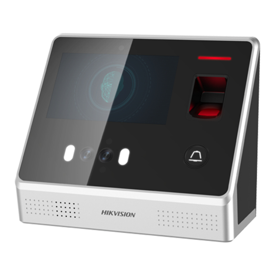
Page 14: Appearance
Note Some device models do not support the function. • Hardware initialization 4 Appearance You can view the device appearance introduction and their descriptions. Refer to the following contents for detailed information of the face recognition terminal. Figure 4-1 Appearance of Face Recognition Terminal Table 4-1 Description of Face Recognition Terminal Name Description... - Page 15 Name Description fingerprint module contains this part. Swipe card within this area. Note Only the device Card Swiping without the Area fingerprint scanning function contains this part. Detect the illumination intensity. When the environment Sensor is too dark, the device will enable the supplement light automatically.
- Page 16 Name Description function, hold the doorbell button for 3s to power off. Note For details about setting the power button function, see System Settings. Plug in the USB flash drive and USB Interface you can import or export the data. Connect to other Wiring Terminals external devices.
-
Page 17: Installation
Name Description Connect to Power Interface power supply. Battery Connect to Connector battery. 5 Installation 5.1 Installation Environment • Install the device at least 2 meters away from the light, and at least 3 meters away from the window or the door. •... -
Page 18: Install Without Gang Box (Wall Mounting)
Note • The installation height here is the recommended height. You can change it according to your actual needs. • For easy installation, drill holes on mounting surface according to the supplied mounting template. Figure 5-2 Installation with Gang Box Diagram 5.3 Install without Gang Box (Wall Mounting) You can install the terminal without gang box on the wall or other surfaces. -
Page 19: Wiring
4. Align the two holes to the mounting plate with the drilled holes. 5. Fix and fasten the screws in the sockets on the wall or other surface. 6. Remove the two screws at the bottom of the device. 7. Align the terminal with the mounting plate and buckle them together. -
Page 20: Wire Secure Door Control Unit
Figure 6-1 Device Wiring Note • You should set the face recognition terminal's Wiegand direction to "Input" to connect to a Wiegand card reader. If connects to an access controller, you should set the Wiegand direction to "Output" to transmit authentication information to the access controller. -
Page 21: Activate Via Device
Before You Start • Get the SADP software from the supplied disk or the official website http://www.hikvision.com/en/ , and install the SADP according to the prompts. • The device and the PC that runs the SADP tool should be within the same subnet. -
Page 22: Activate Device Via Client Software
Status of the device becomes Active after successful activation. 5. Modify IP address of the device. 1) Select the device. 2) Change the device IP address to the same subnet as your computer by either modifying the IP address manually or checking Enable DHCP. -
Page 23: Basic Operation
8 Basic Operation 8.1 Login You should enter the system backend first before setting the device parameters. First Login If it is the first time to login, follow the descriptions below to login. Tap the settings icon at the lower right corner of the initial page and enter the device activation password on the Input Password page. -
Page 24: Set Wi-Fi Parameters
3. Tap IP Address, Subnet Mask, or Gateway and input the parameters. 4. Tap OK to save the settings. Note The device's IP address and the computer IP address should be in the same IP segment. 5. Tap to save the network parameters. 8.2.2 Set Wi-Fi Parameters You can enable the Wi-Fi function and set the Wi-Fi related parameters. -
Page 25: Set Wiegand Parameters
Note Unit represents the secure door control unit and Reader represents the card reader. 4. Tap to save the network parameters. Note If you change the external device, and after you save the device parameters, the device will reboot automatically. 8.2.4 Set Wiegand Parameters You can set the Wiegand transmission direction and the Wiegand mode. - Page 26 2. Edit the employee ID. Note • The employee ID should be between 1 and 99999999. • The employee ID should not start with 0 and should not be duplicated. 3. Tap the Name field and input the user name on the soft keyboard.
-
Page 27: Add Fingerprint
The User is the normal user. The user can only authenticate or take attendance on the initial page. 9. Optional: Tap the Schedule Template field, select a schedule template and save the settings. 10. Tap to save the settings. 8.3.2 Add Fingerprint Add a fingerprint for the user and the user can authenticate via the added fingerprint. -
Page 28: Add Card
10. Tap to save the settings. 8.3.3 Add Card Add a card for the user and the user can authenticate via the added card. Steps 1. Tap User + to enter the Add User page. 2. Tap the Employee ID. field and edit the employee ID. Note •... -
Page 29: Set Authentication Mode
Add a password for the user and the user can authenticate via the password. Steps 1. Tap User + to enter the Add User page. 2. Tap the Employee ID. field and edit the employee ID. Note • The employee ID should be between 1 and 99999999. •... -
Page 30: Search And Edit User
You can combine different authentication modes together according to your actual needs. 3. Tap to save the settings. 8.3.6 Search and Edit User After adding the user, you can search the user and edit it. Search User On the User Management page, Tap to enter the Search User page. -
Page 31: Import Data
Note • The supported USB flash drive format is FAT 32. • The system supports the USB flash drive with the storage of 1G to 32G. Make sure the free space of the USB flash drive is more than 512M. •... -
Page 32: Set Auto Attendance
Figure 8-6 Manual Mode 3. Enable the Attendance Status function. Result When you authenticate on the initial page, you will enter the Select Status page. Select a status to take attendance. Note If you do not select a status, the authentication will be failed and it will not be marked as a valid attendance. -
Page 33: Set Manual And Auto Attendance
Result When you authenticate on the initial page, the authentication will be marked as the configured attendance status according to the configured schedule. 8.5.3 Set Manual and Auto Attendance Set the attendance mode as manual and auto and the system will auto change the attendance status according to the configured parameters. -
Page 34: Authenticate Via 1:1 Matching
After network configuration, system parameters configuration and user configuration, you can go back to the initial page for identity authentication. The system will authenticate person according to the configured authentication mode. You can authenticate identity via 1:1 matching or 1:N matching. 1:N Matching Compare the captured face picture or the collected fingerprint picture with all face pictures or all fingerprint pictures stored in... -
Page 35: Set Basic Parameters
8.7.1 Set Basic Parameters You can set the device ID, time format, keyboard sound, voice prompt, voice volume, application mode, power button, auto enable supplement light, brightness, language, and threshold for auto enabling Supplement Light. On the Home page, tap System (System Settings) to enter the System Settings page. -
Page 36: Set Face Picture Parameters
Parameter Description If enabling the function, when it is too dark, the Auto Enable supplement light will be turned on automatically. Supplement If disabling the function, the supplement light will be Light on all the time. You can set the supplement light’s brightness. The brightness ranges from 0 to 100. -
Page 37: Set Fingerprint Parameters
Parameter Description The time interval between two continuous face recognitions when authenticating. By default, it is 2s. Face Recognition Note Interval You can input the number from 1 to 10 or 255. 255 refers to infinite. If enabling the function, the system will compare the adding face picture with all Duplicated pictures in the database when adding a... -
Page 38: Set Access Control Parameters
Figure 8-12 Time Parameters 8.8 Set Access Control Parameters You can set the access control permissions, including the functions of authentication mode, door magnetic sensor, anti- passback, lock locked time, door open timeout alarm, etc. On the Home page, tap ACS (Access Control Settings) to enter the Access Control Settings page. -
Page 39: Maintenance
Parameter Description use multiple authentication modes. • If you adopt multiple authentication modes, you should authenticate other methods before authenticating face. Card Reader Select the card reader's Authentication authentication mode. Mode You can select "Remain Open" or "Remain Closed" according to your Door Contact actual needs. -
Page 40: Data Management
Note • Do not power off during the device upgrade. • The upgrading file should be in the root directory. • The upgrading file name should be digicap.dav. Figure 8-14 Upgrade 8.9.2 Data Management On the Data Management page, you can delete all events, delete user data, delete all data, clear permission, delete captured pictures, restore to factory settings, or restore to default settings. -
Page 41: Log Query
Parameters Description Restore the system to the factory Restore to settings. The device will reboot after the Factory setting. Restore the system to the default settings. The system will save the Restore to communication settings and the remote Default user settings. Other parameters will be restored to default. -
Page 42: View System Information
Figure 8-17 Test 8.10 View System Information View device capacity, device information, and the open source software license. View Capacity You can view the added user's number, the face picture's number, the card's number, the password's number, and the fingerprint's number. -
Page 43: Client Software Configuration
9 Client Software Configuration 9.1 Person Management You can add person information to the system for further operations such as access control, video intercom, time and attendance, etc. You can manage the added persons such as issuing cards to them in a batch, importing and exporting person information in a batch, etc. -
Page 44: Issue A Card To One Person
4. Enter the basic information including person name, gender, tel, email address, etc. 5. Optional: Set the effective period of the person. Once expired, the credentials and access control settings of the person will be invalid and the person will have no authorization to access the doors\floors. -
Page 45: Upload A Face Photo From Local Pc
This card is used for the inspection staff to check the their attendance of inspection. By swiping the card on the specified card reader, the person is marked as on duty of inspection at that time. Dismiss Card By swiping the card on the card reader, it can stop the buzzing of the card reader. -
Page 46: Collect Face Via Access Control Device
Note Enter the person's basic information first. For details about configuring person's basic information, refer to Configure Basic Information. 3. Click Add Face in the Basic Information panel. 4. Select Take Photo. 5. Connect the face scanner to the PC running the client. 6. -
Page 47: Collect Fingerprint Via Client
9.1.7 Collect Fingerprint via Client Collecting fingerprints locally means you can collect the fingerprint via the fingerprint recorder connected directly to the PC running the client. The fingerprints recorded can be used as credentials of the persons to access the authorized doors. Before You Start Connect the fingerprint recorder to the PC running the client. -
Page 48: Configure Access Control Information
3. In the Credential Fingerprint panel, click +. 4. In the pop-up window, select the collection mode as Remote. 5. Select an access control device which supports fingerprint recognition function from the drop-down list. 6. Collect the fingerprint. 1) Click Start. 2) Place and lift your fingerprint on the fingerprint scanner of the selected access control device to collect the fingerprint. -
Page 49: Customize Person Information
If the person is a visitor, set the maximum times of authentications, including access by card and fingerprint to limit the visitor's access times. Note The maximum times of authentications should be between 1 and 100. Device Operator For person with device operator role, he/she is authorized to operate on the access control devices. -
Page 50: Configure Additional Information
After bound, you can call this person by calling the indoor station and perform video intercom with her/him. Steps 1. Enter Person module. 2. Select an organization in the organization list to add the person and click Add. Note Enter the person's basic information first. For details about configuring person's basic information, refer to Configure Basic Information. -
Page 51: Import Person Pictures
You can enter the information of multiple persons in a predefined template (a CSV file) to import the information to the client in a batch. Steps 1. Enter the Person module. 2. Select an added organization in the list, or click Add in the upper-left corner to add an organization and then select it. -
Page 52: Export Person Information
Note • The (folder of) face pictures should be in ZIP format. • Each picture file should be in JPG format and should be no larger than 200 KB. • Each picture file should be named as "Person ID_Name". The Person ID should be the same with that of the imported person information. -
Page 53: Get Person Information From Access Control Device
9.1.18 Get Person Information from Access Control Device If the added access control device has been configured with person information (including person details, fingerprint, and issued card information), you can get the person information from the device and import them to the client for further operations. -
Page 54: Report Card Loss
All the added persons with no card issued will display. 3. Set the card issuing parameters. For details, refer to Set Card Issuing Parameters. 4. Click Initialize to initialize the card enrollment station or card reader to make it ready for issuing cards. 5. -
Page 55: Configure Schedule And Template
Card Enrollment Station Select the model of the connected card enrollment station Note Currently, the supported card enrollment station models include DS-K1F100-D8, DS-K1F100-M, DS-K1F100-D8E, and DS- K1F180-D8E. Card Type This field is only available when the model is DS-K1F100-D8E or DS-K1F180-D8E. -
Page 56: Add Template
1. Click Access Control Template Holiday to enter the Holiday page. 2. Click Add on the left panel. 3. Create a name for the holiday. 4. Optional: Enter the descriptions or some notifications of this holiday in the Remark box. 5. - Page 57 Note There are two default templates: All-Day Authorized and All- Day Denied, and they cannot be edited or deleted. All-Day Authorized The access authorization is valid in each day of the week and it has no holiday. All-Day Denied The access authorization is invalid in each day of the week and it has no holiday.
-
Page 58: Set Access Group To Assign Access Authorization To Persons
9.3 Set Access Group to Assign Access Authorization to Persons After adding the person and configuring the person's credentials, you can create the access groups to define which person(s) can get access to which door(s) and then apply the access group to the access control device to take effect. -
Page 59: Configure Advanced Functions
3) View the apply status in the Status column or click Applying Statusto view all the applied access group(s). The selected persons in the applied access groups will have the authorization to enter/exit the selected doors/door stations with their linked card(s) or fingerprints. 9. - Page 60 Display the card information when authenticating. Display Person Information Display the person information when authenticating. Overlay Person Info. on Picture Display the person information on the captured picture. Voice Prompt If you enable this function, the voice prompt is enabled in the device.
- Page 61 Door Contact You can set the door sensor as remaining closed or remaining open. Usually, it is remaining closed. Exit Button Type You can set the exit button as remaining closed or remaining open. Usually, it is remaining open. Door Locked Time After swiping the normal card and relay action, the timer for locking the door starts working.
- Page 62 Steps 1. Click Access Control Advanced Function Device Parameter . 2. In the device list on the left, click to expand the door, select a card reader and you can edit the card reader's parameters on the right. 3. Edit the card reader basic parameters in the Basic Information page.
- Page 63 View the default card reader authentication mode. Fingerprint Capacity View the maximum number of available fingerprints. Existing Fingerprint Number View the number of existed fingerprints in the device. Score The device will score the captured picture according to the yaw angle, pitch angle, and pupillary distance. If the score is less than the configured value, face recognition will be failed.
- Page 64 4. Click OK. 5. Optional: Click Copy to, and then select the card reader(s) to copy the parameters in the page to the selected card reader(s). Configure Parameters for Alarm Input After adding the access control device, you can configure the parameters for its alarm inputs.
-
Page 65: Configure Remaining Open/Closed
5. Optional: Set the switch on the upper right corner to ON to trigger the alarm output. Configure Parameters for Lane Controller After adding the lane controller to the client, you can configure its parameters for passing through the lane. Steps 1. - Page 66 Steps 1. Click Access Control Advanced Function Remain Open/Closed to enter the Remain Open/Closed page. 2. Select the door or elevator controller that need to be configured on the left panel. 3. To set the door or elevator controller status during the work day, click the Week Schedule and perform the following operations.
-
Page 67: Configure Multi-Factor Authentication
• M ove the cursor to the time duration and drag the time duration on the timeline bar to the desired position when the cursor turns to • C lick the time duration and directly edit the start/end time in the appeared dialog. •... - Page 68 5. Enter the maximum interval when entering password. 6. Add an authentication group for the selected access control point. 1) Click Add on the Authentication Groups panel. 2) Select a configured template as the authentication template from the drop-down list. Note For setting the template, refer to Configure Schedule and Template.
-
Page 69: Configure Custom Wiegand Rule
Note • For each access control point (door), up to four authentication groups can be added. • For the authentication group of which authentication type is Local Authentication, up to 8 person/card groups can be added to the authentication group. •... -
Page 70: Configure Card Reader Authentication Mode And Schedule
1) Click Set Rule to open the Set Output Transformation Rules window. Figure 9-2 Set Output Transformation Rule 2) Select rules on the left list. The selected rules will be added to the right list. 3) Optional: Drag the rules to change the rule order. 4) Click OK. -
Page 71: Configure First Person In
4. Click the icon to select a card reader authentication mode, and drag the cursor to draw a color bar on the schedule, which means in that period of time, the card reader authentication is valid. 5. Repeat the above step to set other time periods. 6. -
Page 72: Configure Anti-Passback
The added first person(s) will list in the First Person List 6. Optional: Select a first person from the list and click Delete to remove the person from the first person list. 7. Click Save. 9.4.7 Configure Anti-Passback You can set to only pass the access control point according to the specified path and only one person could pass the access control point after swiping the card. -
Page 73: Configure Other Parameters
Steps Note • Multi-door Interlocking function is only supported by the access control device which has more than one access control points (doors). • Either the anti-passing back or multi-door interlocking function can be configured for an access control device at the same time. - Page 74 A media access control address (MAC address) is a unique identifier assigned to the network interface for communications on the physical network segment. The maximum transmission unit (MTU) of the network interface. 6. Click Save. Set Network Parameters After adding the access control device, you can set the device log uploading mode, and create EHome account via wired or wireless network.
- Page 75 7. Enter the port number for the protocol. Note The port number of the wireless network and wired network should be consistent with the port number of EHome. 8. Select the Protocol Type as EHome. 9. Set an account name for the network center. 10.
- Page 76 Before You Start Before setting the capture parameters, you should set the picture storage first to define where the captured pictures are saved. For details, refer to . Steps Note This function should be supported by the device 1. Enter the Access Control module. 2.
- Page 77 2. On the navigation bar on the left, enter Advanced Function More Parameters . 3. Select an access control device in the device list and click Face Recognition Terminal. 4. Set the parameters. Note These parameters displayed vary according to different device models.
- Page 78 6. Click Save. • The configured parameters will be applied to the device automatically. • After changing the working mode or connection mode, the device will reboot automatically. Set Wiegand Parameters You can set the access control device's Wiegand channel and the communication mode.
-
Page 79: Configure Linkage Actions For Access Control
6. Click Save to save the settings. 9.5 Configure Linkage Actions for Access Control The events triggered by the access control devices, doors, card readers, and alarm inputs, as well as the card swiping of persons, mobile terminal's MAC address detected, and employee No. detected, can trigger a series of linkage actions to notify the security personnel and record the events. -
Page 80: Configure Device Actions For Access Event
5. Enable the event so that when the event is detected, en event will be sent to the client and the linkage actions will be triggered. 6. Optional: Click Copy to... to copy the event settings to other access control device, alarm input, door/elevator, or card reader. -
Page 81: Configure Device Actions For Card Swiping
The audio prompt will be triggered. And the select audio index related audio content will be played according to the configured play mode. 7. Click Save. 8. Optional: After adding the device linkage, you can do one or more of the following: Edit Linkage Select the configured linkage settings in the Settings... -
Page 82: Configure Device Linkage For Mobile Terminal's Mac Address
Note The device should support alarm input function. Access Point The door status of open, close, remain open, or remain closed will be triggered. Audio Play The audio prompt will be triggered. And the select audio index related audio content will be played according to the configured play mode. -
Page 83: Configure Device Actions For Person Id
The real-time capture will be triggered. Recording The recording will be triggered. Note The device should support recording. Alarm Output The alarm output will be triggered for notification. Alarm Input Arm or disarm the alarm input. Note The device should support alarm input function. Access Point The door status of open, close, remain open, or remain closed will be triggered. -
Page 84: Door/Elevator Control
7. In the Linkage Target area, set the property target to enable this action. Buzzer on Controller The audible warning of access control device will be triggered. Buzzer on Reader The audible warning of card reader will be triggered. Capture The real-time capture will be triggered. -
Page 85: Control Door Status
the icons used for control will not show. For setting the user permission, refer to . 9.6.1 Control Door Status You can control the status for a single door, including opening door, closing door, remaining the door open, and remaining the door closed. -
Page 86: Check Real-Time Access Records
Steps Note • You can control the elevator via the current client if it is not armed by other client. The elevator cannot be controlled by other client software if the elevator status changes. • Only one client software can control the elevator at one time. •... -
Page 87: Time And Attendance
4. Optional: Click the event to view the accessed person details, including person pictures (captured picture and profile), person No., person name, organization, phone, contact address, etc. Note You can double click the captured picture to enlarge it to view the details. - Page 88 When you work for certain period after end-work time on workday, you will reach different overtime level: overtime level 1, overtime level 2 and overtime level 3 . You can set different pay rate for three overtime levels, respectively. Pay Rate Set corresponding pay rates for three overtime levels, which can be generally used to calculate total work hours.
- Page 89 5. Set the first day of the holiday. 6. Enter the number of the holiday days. 7. Set the attendance status if the employee works on holiday. 8. Optional: Check Repeat Annually to make this holiday setting effective every year. 9.
- Page 90 You can customize the leave type (major leave type and minor leave type) according to actual needs. You can also edit or delete the leave type. Steps 1. Enter the Time & Attendance module. 2. Click Attendance Settings Leave Type to enter the Leave Type Settings page.
- Page 91 You can add break time and set start time, end time, duration, calculation mode and other parameters for the break. The added break time can also be edited or deleted. Steps 1. Click Time & Attendance Timetable . The added timetables are displayed in the list. 2.
-
Page 92: Add Timetable
Set the date format and time format according to the actual needs. Attendance Status Mark in Report Enter the mark and select the color. The related fields of attendance status in the report will display with the mark and color. Weekend Mark in Report Enter the mark and select the color. -
Page 93: Add Shift
Edit Timetable Select a timetable from the list to edit related information. Delete Select a timetable from the list and click Timetable Delete to delete it. 9.7.3 Add Shift You can add the shift for the shift schedule. Before You Start Add a timetable first. - Page 94 You can set department schedule, person schedule, and temporary schedule. Set Department Schedule You can set the shift schedule for one department, and all the persons in the department will be assigned with the shift schedule. Before You Start In Time & Attendance module, the department list is the same with the organization.
- Page 95 Steps Note The person schedule has the higher priority than department schedule. 1. Click Time & Attendance Shift Schedule to enter the Shift Schedule Management page. 2. Click Person Schedule to enter Person Schedule page. 3. Select the organization and select the person(s). 4.
-
Page 96: Manually Correct Check-In/Out Record
If Non-Workday is selected, you need to set the following parameters. Calculated as Select normal or overtime level to mark the attendance status for temporary schedule. Timetable Select a timetable from drop-down list. Multiple Shift Schedule It contains more than one timetables. The person can check in/out in any of the timetables and the attendance will be effective. -
Page 97: Add Leave And Business Trip
2. Click Correct Check-In/Out to enter adding the check-in/out correction page. 3. Select person from left list for correction. 4. Select the correction date. 5. Set the check-in/out correction parameters. - Select Check-in and set the actual start-work time. - Select Check-out and set the actual end-work time. Note You can click to add multiple check in/out items. -
Page 98: Calculate Attendance Data
Note You can set the leave type in Attendance Settings. For details, refer to Configure Leave Type. 6. Set the time for leave. 7. Optional: Enter the remark information as desired. 8. Click Save. 9. Optional: After adding the leave and business trip, perform one of the following operations. -
Page 99: Attendance Statistics
2. Click Attendance Statistics Calculate Attendance . 3. Set the start time and end time to define the attendance data range. 4. Set other conditions, including department, person name, employee No. and attendance status. 5. Click Calculate. Note It can only calculate the attendance data within three months. 6. - Page 100 5. Optional: Click Get from Device to get the attendance data from the device. 6. Optional: Click Reset to reset all search conditions and edit the search conditions again. 7. Click Search. The result displays on the page. You can view the employee's required attendance status and check point.
- Page 101 Select one report type and this report will be generated. Report Time The time to be selected may vary for different report type. Person Select the added person(s) whose attendance records will be generated for the report. 5. Optional: Set the schedule to send the report to the email address(es) automatically.
-
Page 102: Tips For Scanning Fingerprint
A. Tips for Scanning Fingerprint Recommended Finger Forefinger, middle finger or the third finger. Correct Scanning The figure displayed below is the correct way to scan your finger: You should press your finger on the scanner horizontally. The center of your scanned finger should align with the scanner center. -
Page 103: Tips When Collecting/Comparing Face Picture
B. Tips When Collecting/Comparing Face Picture The position when collecting or comparing face picture is as below: Positions (Recommended Distance: 0.5 m) Expression • Keep your expression naturally when collecting or comparing face pictures, just like the expression in the picture below. •... -
Page 105: Relationship Between Device Height, Person Height, And Standing Distance
C. Relationship between Device Height, Person Height, and Standing Distance... -
Page 106: Tips For Installation Environment
D. Tips for Installation Environment 1. Light Source Illumination Reference Value Candle: 10Lux Bulb: 100~850Lux Sunlight: More than 1200Lux 2. Install the device at least 2 meters away from the light, and at least 3 meters away from the window or door. 3.Avoid backlight, direct and indirect sunlight... -
Page 107: Dimension
E. Dimension...
Need help?
Do you have a question about the DS-K1T605 Series and is the answer not in the manual?
Questions and answers