Table of Contents
Advertisement
Quick Links
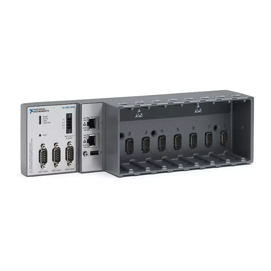
GETTING STARTED GUIDE
NI cRIO-9068
Reconfigurable Embedded Chassis with Integrated Intelligent Real-
Time Controller for CompactRIO
This document describes how to begin using the NI cRIO-9068.
Safety Guidelines
Caution
Product misuse can result in a hazard. You can compromise the safety protection
built into the product if the product is damaged in any way. If the product is
damaged, return it to NI for repair.
Safety Guidelines for Hazardous Locations
The cRIO-9068 is suitable for use in Class I, Division 2, Groups A, B, C, D, T4 hazardous
locations; Class I, Zone 2, AEx nA IIC T4 and Ex nA IIC T4 hazardous locations; and
nonhazardous locations only. Follow these guidelines if you are installing the cRIO-9068 in a
Do not operate the cRIO-9068 in a manner not specified in this document.
Advertisement
Table of Contents

Related Manuals for National Instruments cRIO-9068


Summary of Contents for National Instruments cRIO-9068
- Page 1 Safety Guidelines for Hazardous Locations The cRIO-9068 is suitable for use in Class I, Division 2, Groups A, B, C, D, T4 hazardous locations; Class I, Zone 2, AEx nA IIC T4 and Ex nA IIC T4 hazardous locations; and...
-
Page 2: Electromagnetic Compatibility Guidelines
Special Conditions for Hazardous Locations Use in Europe and Internationally The cRIO-9068 has been evaluated as Ex nA IIC T4 Gc equipment under DEMKO 12 ATEX 1202658X and is IECEx UL 14.0089X certified. Each device is marked II 3G and is suitable for use in Zone 2 hazardous locations, in ambient temperatures of -40 °C ≤... -
Page 3: Special Conditions For Marine Applications
In addition, take precautions when designing, selecting, and installing measurement probes and cables to ensure that the desired EMC performance is attained. Preparing the Environment Ensure that the environment in which you are using the cRIO-9068 meets the following specifications. Operating temperature -40 °C to 70 °C... -
Page 4: Verifying The Kit Contents
2. NI Driver Media 3. Getting Started Guide Installing Software on the Host Computer Before using the cRIO-9068, you must install the following application software and device drivers on the host computer in this order: LabVIEW 2013 or later LabVIEW Real-Time Module 2013 or later LabVIEW FPGA Module 2013 or later NI CompactRIO Device Drivers 13.0 or later... - Page 5 Complete the following steps to install a C Series module. Verify that power is not connected to the I/O connector(s) on the C Series module. If the system is in a nonhazardous location, the cRIO-9068 can be powered on when you install modules.
- Page 6 4. USB Host Port 9. Reset Buttom 5. USB Cable Retention Mount 10. LEDs Connecting the cRIO-9068 to Ground You must connect the cRIO-9068 grounding terminal to the grounding electrode system of the facility. What to Use • Ring lug •...
- Page 7 C Series modules. The cRIO-9068 has a primary power input, V1, and a secondary power input, V2. The POWER LED on the cRIO-9068 indicates which power input is in use, as shown in the following table.
- Page 8 Explorer (MAX) under the Network Settings tab. Power on the host computer or Ethernet hub. Connect the RJ-45 Gigabit Ethernet port 1 on the cRIO-9068 to the host computer or Ethernet hub using a standard Category 5 (CAT-5) or better shielded, twisted-pair Ethernet cable.
-
Page 9: Setting A System Password
The cRIO-9068 attempts to initiate a DHCP network connection the first time you connect using Ethernet. The cRIO-9068 connects to the network with a link-local IP address with the form 169.254. if it is unable to initiate a DHCP connection. -
Page 10: System Reset
Click Next. Select NI Scan Engine from the software add-ons. Select any additional software to install. If you plan on using the cRIO-9068 with the LabVIEW FPGA Module, you can click Next. Click NI Scan Engine if you plan on using the cRIO-9068 without the LabVIEW FPGA Module. - Page 11 Table 3. STATUS LED Indicators LED Pattern Indication Blinks twice and The cRIO-9068 is in safe mode. Software is not installed, which is the pauses factory default state, or software has been improperly installed on the cRIO-9068. An error can occur when an attempt to upgrade the software is interrupted.
-
Page 12: Where To Go Next
Table 3. STATUS LED Indicators (Continued) LED Pattern Indication Continuously blinks The cRIO-9068 has not booted into NI Linux Real-Time. The cRIO-9068 either booted into an unsupported operating system, was interrupted during the boot process, or detected an unrecoverable software error. - Page 13 United States, visit the Worldwide Offices section of ni.com/ niglobal to access the branch office websites, which provide up-to-date contact information, support phone numbers, email addresses, and current events. cRIO-9068 Getting Started Guide | © National Instruments | 13...
- Page 14 CONTAINED HEREIN AND SHALL NOT BE LIABLE FOR ANY ERRORS. U.S. Government Customers: The data contained in this manual was developed at private expense and is subject to the applicable limited rights and restricted data rights as set forth in FAR 52.227-14, DFAR 252.227-7014, and DFAR 252.227-7015. © 2013—2016 National Instruments. All rights reserved. 376007B-01 Apr16...
Need help?
Do you have a question about the cRIO-9068 and is the answer not in the manual?
Questions and answers