
Related Manuals for Euroboor TUBE.55-T


Summary of Contents for Euroboor TUBE.55-T
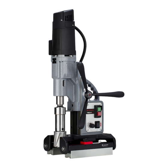
- Page 1 Operators manual version 1.2 EN Magnetic drilling machine TUBE.55-T Serial no.: _______________________ Date of purchase: _______________________...
- Page 2 Congratulations on your purchase of the Euroboor TUBE.55-T portable magnetic drilling machine. Your model is designed to produce superior holes quickly and efficiently. Through years of experience, constant innovation and development, Euroboor is committed to provide you with metal cutting tools and products to help you be more productive.
-
Page 3: Table Of Contents
Table of contents 1. Safety 1.1 General safety instructions 1.2 Specific safety information 2. Description 2.1 Intended use 2.2 Description and features 2.3 Box contents 2.4 Serial number 2.5 Technical data 2.6 Symbols 2.7 Environmental 3. Preparation & adjustment 3.1 Assembly 3.2 Prior to use 4. -
Page 4: Safety
1. Safety 1.1 General safety instructions Do not use this power tool before you have thoroughly read and completely understood this Instruction Manual and the “General Safety Instructions”, including the figures, specifications, safety regulations and the signs indicating DANGER, WARNING and CAUTION. WARNING: When using electrical tools basic safety precautions should always be followed to reduce the risk of fire, electrical shock and personal injury including following. - Page 5 If damaged, have the tool serviced before using. Many accidents are caused by poorly maintained tools. 9. Use only accessories that are recommended by Euroboor for your model. Accessories that may be suitable for one machine, may become hazardous when used on another machine.
-
Page 6: Specific Safety Information
1.2 Specific safety information • Keep your fingers well out of the drill area; • Avoid touching the drilled core that is automatically ejected by the centering pin when the working procedure is finished. Contact with the core when it is hot, or if it falls, can cause personal injuries;... -
Page 7: Description
EUROBOOR. The magnetic drilling machine can be used horizontally, vertically or overhead. -
Page 8: Box Contents
2.3 Box contents 1 Carrying case 1 Magnetic drilling machine 1 Instruction manual 3 Handles 1 Oil tank + attachment pin 1 Bottle cutting oil 3 Allen keys (2.5, 4, 5) 1 Safety chain 1 Morse Taper 3 spindle 1 Spindle drift 4 Tap collets (DIN 376 M10/M12/M14/M16) 1 Set of ear plugs 1 Pair of safety glasses... -
Page 9: Technical Data
2.5 Technical data TUBE.55-T ANNULAR CUTTERS Ø 12 – 55 mm Ø 7/16 – 2 3/16” TWIST DRILLS Ø 1 – 23 mm 1/16 – 15/16” THREADING M3 – M20 1/8 – 13/16” COUNTERSINKING Ø 10 – 60 mm Ø 3/8 – 2 3/8”... -
Page 10: Symbols
2.6 Symbols Symbol Term, meaning Explanation Be absolutely sure to read the enclosed Read documentation documentation such as the Instruction Manual and the General Safety Instructions. Wear ear protection Use ear protection during operation. Wear eye protection Use eye-protection during operation. Danger/warning/caution Observe the information in the adjacent text! European conformity symbol... -
Page 11: Environmental
2.7 Environmental Separate collection. This product must not be disposed of with normal household waste. Separate collection of used products and packaging allows materials to be recycled and used again. Re-use of recycled materials helps prevent environmental pollution and reduces the demand for raw materials. -
Page 12: Preparation & Adjustment
3. Preparation & adjustment 3.1 Assembly WARNING: To reduce the risk of injury, turn unit off and disconnect machine from power source before installing and removing accessories, before adjusting or changing set- ups or when making repairs. Be sure all switches are in the OFF position. An accidental start-up can cause injury. -
Page 13: Prior To Use
Please make sure that the contacting surface for the magnet is level, clean and rust-free. Remove any varnish or primer. When working on materials that are not magnetizable, suitable fixation devices, obtainable as accessories from EUROBOOR, e. g. suction plate, vacuum plate or pipe-drilling device must be used. -
Page 14: Using The Machine
4. Using the machine WARNING: Always observe the safety instructions and applicable regulations. WARNING: To reduce the risk of serious personal injury, turn tool off and disconnect tool from power source before making any adjustments or removing/installing attachments or accessories. 4.1 Control panel The control panel on your magnetic drilling machine is designed for maximum operating facility and safety. -
Page 15: Morse Taper Spindle
4.2 Morse taper spindle [image 2-3] [image 2-4] 1. Make sure the inside of the output shaft and the Morse Taper spindle are clean and free of grease 2. Align the coolant ring rotation limiter with the recess in the gearbox (A) 3. -
Page 16: Gearbox
4.3 Gearbox 1. To select the correct gear from neutral (horizontal) position: a. Rotate the switch counter clockwise to position o, this is gear 1 b. Rotate the switch clockwise to position oo, this is gear 2 2. A gear is only correctly selected when the gearbox switch is aligned with the indicators on the gearbox. -
Page 17: Magnet Base
4.4 Magnet base By combining Magswitch’s patent-pending rotating magnet technology and Euroboor’s smartest magnetic drilling unit yet, we have created a tool that is capable of quickly and safely drilling on contoured and flat surfaces. Magswitch LAY magnets allow for a much more efficient field on thinner material, allowing more consistent tip forces. -
Page 18: Switching Motor On And Off
Activating the magnets Both magnet arrays are to be handled individually. Make sure the magnet arrays are switched OFF (narrow part of both ratcheting action handles pointing to the marking “OFF”) Place the magnetic drilling machine on the workpiece in the desired location, and make sure both magnet arrays are positioned correctly and the machine is in a stable position Rotate the ratcheting action handles: o For precise positioning: partly (around 90 degrees) clockwise, this allows for some... -
Page 19: Motor Rotation
4.6 Motor rotation The rotational direction of the motor can be changed. Switch in up position (R) will make the motor rotate clockwise Switch in down position (L) will make the motor rotate anticlockwise Before switching the rotational direction of the motor and spindle, make sure the motor is switched off first to prevent machine and tool damage. -
Page 20: Gyro-Tec Safety
4.9 GYRO-TEC safety This Euroboor magnetic drilling machine is equipped with GYRO-TEC safety functionality. It features a gyroscopic sensor which detects acceleration and displacement in any direction. Whenever the machine recognizes a sudden, unwanted movement the motor will be shut down automatically by the machine electronics. -
Page 21: Temperature Control
WARNING: Do not use the lubrication system in vertical or overhead drilling applications. Instead use Euroboor cutting paste Make sure to use only suitable cutting oil or fluid. Euroboor offers a wide range of cutting lubricants for all tool and material combinations. Proper cooling will help you create better and faster results,... -
Page 22: Working With Operation Tools
5 Working with operation tools 5.1 Annular cutters Annular cutters only cut material at the periphery of the hole, rather than converting the entire hole to shavings. As a result, the energy required to make a hole is lower than for a twist drill. When drilling with an annular cutter, it is not necessary to drill a pilot hole. - Page 23 2. Precisely mark the centre of the hole 3. Use the pilot pin to position the machine and in the correct position, with the tip of the pilot pin to meet the marked center of the hole. 4. Switch on the magnet and verify that the drill is in the right position and that the machine is pushed tight against the work piece.
-
Page 24: Twist Drills
5.2 Twist drills 1. Remove the Morse Taper arbor (see chapter Gearbox) 2. Fit the twist drill a. Straight shank twist drills [image 3-2] b. Morse Taper shank twist drills [image 3-3] Morse Taper 2 [image 3-4] Morse Taper 3... -
Page 25: Machine Taps
Steps 4-12: see chapter Annular cutters. Make sure the machine runs at maximum speed for twist drills! 5.3 Machine taps This TUBE.55-T model is equipped with a reversible direction of rotation and can also be used for cutting threads. Proceed as follows for cutting threads: 1. Install the tap [image 3-5] 2. -
Page 26: Countersinks
Switch on the machine again and allow the machine tap to come completely out of the work piece. Then guide the motor unit slide upwards at handles to avoid damaging the start of the thread. DO NOT LET YOUR TAP PUSH UP THE MOTOR UNIT BY ITSELF!! Make sure the properly lubricate while performing tapping work, see chapter Annular cutters 5.4 Countersinks Thanks to its wide range of operating speeds, the machine can also be used for reaming or counter-... -
Page 27: Maintenance
6. Maintenance Your EUROBOOR power tool has been designed to operate over a long period of time with a minimum of maintenance. Continuous satisfactory operation depends upon proper tool care and regular cleaning. CAUTION: To reduce the risk of injury, turn unit off and disconnect machine from power source before installing and removing accessories, before adjusting or changing set- ups or when making repairs. - Page 28 Repair, modification and inspection of Euroboor Magnetic drilling machines must be done by EUROBOOR or an EUROBOOR authorized dealer. The spare parts list will be helpful if presented with the machine to the Euroboor dealer for service when requesting repair or other maintenance.
-
Page 29: Trouble Shooting
7. Trouble shooting Motor does not work - Damaged or defective wiring - Carbon brushes are stuck or worn out - Defective magnet switch - Defective On / Off switch - Defective control unit - Defective armature and/or field Annular cutters break quickly, - Clearance in the guide holes are bigger than the hole - Bent spindle... - Page 30 Fuse blows when motor is started - Damaged or defective wiring - Wrong value fuse - Motor running roughly - Defective armature and / or field - Carbon brushes worn out - Defective control unit Rotation system free stroke too - Loose or defective gear-rack long - Defective rotation system...
-
Page 31: Exploded View & Spare Part List
8. Exploded view & spare part list 8.1 Exploded view... -
Page 34: Spare Part List
Gear 34/40Z 100.0152 Left/Right switch 050.0231 Gear 032T.0057 Potentiometer 100.4496 Key 5x5x28 055T.0006 Screw 020.0156 Screw 055T.1013 Magnetic base complete TUBE.55-T 050.0074 Rack CAS.TUBE55T Metal case 050.0076 Circlip KSP.Q2 Coolant tank 050.0463 Gear 1 x 45T IBO.10.200 Oil bottle 050.0462 Washer SAF.300... -
Page 35: Wiring Diagram
8.3 Wiring diagram...
Need help?
Do you have a question about the TUBE.55-T and is the answer not in the manual?
Questions and answers