Table of Contents
Advertisement
Quick Links
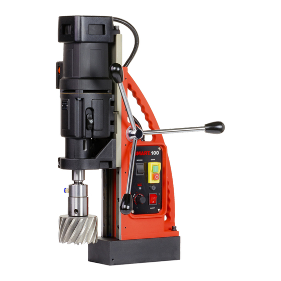
ANNULAR CUTTERS
TWIST DRILLS
THREADING
COUNTERSINKING
LENGTH
WIDTH
HEIGHT
STROKE
WEIGHT
MAGNET (L x W x H)
220 x 110 x 64 m
100
Ø 12 - 100 mm
Ø 1/2" - 13 15/16"
Ø 1 - 31.75 mm
Ø 1/16" - 1 1/4"
M3 - M30
1/8" - 1 3/16"
Ø 10 - 105 mm
Ø 3/8" - 4 1/8"
340 mm
13 3/8"
310 mm
12 3/16"
510 - 710 mm
20 1/16" - 27 15/16"
260 mm
10 1/4"
28 kg
61.7 lbs
8 11/16" x 4 5/16" x 2 1/2"
magnetic drilling machine
MAGNETIC FORCE
MOTOR POWER
TOTAL POWER
SPEED (no load)
SPEED 1,800 W (loaded)
SPINDLE WELDON
POWER SOURCE
2,500 kg
5,512 lbs
1,800 W
16.4 A
1,950 W
17.7 A
(I) 40 - 110 rpm
(III) 140 - 380 rpm
(II) 65 - 180 rpm
(IV) 220 - 610 rpm
(I) 85 rpm
(III) 270 rpm
(II) 152 rpm
(IV) 480 rpm
MT3 19.05 mm
MT3 3/4"
220 - 240V AC
110 - 120V AC
50 - 60 Hz
60 Hz
Advertisement
Table of Contents

Related Manuals for Euroboor SMART.100


Summary of Contents for Euroboor SMART.100
- Page 1 magnetic drilling machine ANNULAR CUTTERS Ø 12 - 100 mm Ø 1/2" - 13 15/16" MAGNETIC FORCE 2,500 kg 5,512 lbs TWIST DRILLS Ø 1 - 31.75 mm Ø 1/16" - 1 1/4" MOTOR POWER 1,800 W 16.4 A THREADING M3 - M30 1/8"...
-
Page 2: Smart.100
Operators manual 1.0 English | February 2022 Magnetic drilling machine SMART.100 Serial number: Date of purchase:... - Page 3 Congratulations on your purchase of the SMART.100 portable magnetic drilling machine. Your model is designed to produce superior holes quickly and efficiently. Before operating your new magnetic drilling machine, please read all instructions in the Operators Manual first. With proper use, care and maintenance this machine will provide you with many years of effective hole drilling performance.
-
Page 4: Table Of Contents
Table of contents SMART.100 ..........................1 Table of contents........................3 1. Safety ............................. 4 1.1 General safety instructions ....................... 4 1.2 Specific safety information ......................6 2. Description ..........................8 2.1 Intended use ..........................8 2.2 Features ............................8 2.3 Case content ..........................9 2.4 Serial number .......................... -
Page 5: Safety
1. Safety 1.1 General safety instructions Do not use this magnetic drilling machine before you have thoroughly read and completely understood this manual, specifically the “General safety instructions” and ‘’Specific safety information’’, including the figures, specifications, safety regulations and the signs indicating DANGER, WARNING and CAUTION. - Page 6 Personal safety 1. Stay alert, watch what you are doing and use common sense when using a magnetic drilling machine. Do not use the machine while tired or under the influence of drugs, alcohol, or medication. A moment of inattention while operating a magnetic drilling machine may result in serious personal injury;...
-
Page 7: Specific Safety Information
Service 1. Tool service must be performed only by qualified repair personnel. Service or maintenance performed by unqualified personnel could result in risk of injury; 2. When servicing a tool, use only identical replacement parts. Follow instructions in the maintenance section of this manual. Use of unauthorised parts or failure to follow maintenance instructions may create a risk of electric shock or injury;... - Page 8 Residual risk In spite of following the relevant safety regulations and their implementation, certain residual risks cannot be avoided. These are: Impairment of hearing; • Risk of personal injury from flying particles; • Risk of burns due to accessories becoming hot during operation; •...
-
Page 9: Description
2. Description 2.1 Intended use This magnetic drilling machine is intended for commercial use as a machine for drilling holes in materials with a magnetisable surface, for tapping, for reaming and for countersinking in a weather-protected environment using the recommended application tools and accessories. The magnetic drilling machine can be used horizontally, vertically or overhead. -
Page 10: Case Content
2.3 Case content 1 x SMART.100 magnetic drilling machine 1 x safety guard 3 x handles 1 x hex key 2.5 mm 1 x hex key 4 mm 1 x hex key 5 mm 1 x hex key 6 mm... -
Page 11: Technical Data
2.5 Technical data Metric Imperial Ø 12 - 100 mm Ø 1/2" - 13 15/16" Annular cutting Ø 1 - 31.75 mm Ø 1/16" - 1 1/4" Twist drilling M3 - M30 1/8" - 1 3/16" Tapping Ø 3/8" - 4 1/8" Ø... - Page 12 Dimensions (mm) Dimensions (")
-
Page 13: Symbols
2.6 Symbols Symbol Term, meaning Explanation Be sure to read the documentation in this user Read documentation manual and specifically the “General safety instructions” and ‘’Specific safety information’’ Wear ear protection Use ear protection during operation Wear eye protection Use eye protection during operation Read and apply the information in the adjacent Danger/warning/caution text! -
Page 14: Preparation & Adjustment
3. Preparation & adjustment 3.1 Assembly WARNING: To reduce the risk of injury, turn machine off and disconnect from power source before installing and removing accessories, before adjusting or changing set- ups or when making repairs. Be sure all switches are in the OFF position. An accidental start-up can cause injury. -
Page 15: Prior To Use
Fitting the safety chain 1. Pass the safety chain through the frame grip opening; 2. Wrap the chain around the workpiece; 3. Securely close the chain using the lock. WARNING: Always use the safety chain when drilling vertically and/or upside down. The safety chain does not replace the magnetic force of the magnetic drilling machine: it is simply used to secure against falling in the event of a magnet malfunction. - Page 16 Useful tips Try a few simple projects using scrap material until you develop a ‘’feel’’ for the – magnetic drilling machine; Let the machine run in for a period of 8-10 hours before starting with big operations. – Do not load the machine too much during this run-in period; Never use the machine with serious overload;...
-
Page 17: Using The Machine
4. Using the machine WARNING: Always observe the safety instructions and applicable regulations. WARNING: To reduce the risk of serious personal injury, turn the machine off and disconnect the machine from power source before making any adjustments or removing/installing attachments or accessories. 4.1 Control panel The control panel is designed for maximum ease of use and safety. -
Page 18: Morse Taper Arbor
4.2 Morse taper arbor [image 4.2] [image 4.3] 1. Make sure the inside of the output shaft and the Morse taper arbor are clean and free of grease; 2. Take the stop pin from the case and screw the threaded end in the motor bracket; 3. -
Page 19: Electromagnet
4.3 Electromagnet Make sure the magnetic drilling machine is placed on a smooth, clean, level and solid surface without any objects or debris to guarantee maximum adhesion. The workpiece must at least be 6 mm (1/4") thick for the magnet to stick and to drill safely. In case the workpiece is between 3 mm (1/8") and 6 mm (1/4"), make sure to make a proper base to create a good magnetic field as shown below. -
Page 20: Four-Speed Gearbox
Make sure that the magnet attaches tightly to the work piece before turning on the motor unit of the magnetic drilling machine. The magnets have two coils; make sure that both coils are in contact with the material. Do not connect any other machine to the same electrical outlet to which the magnetic drilling machine is plugged into, as it may result in the loss of magnetic force. -
Page 21: Motor Rotation
4.6 Motor rotation The rotational direction of the motor can be changed: Switch in up position (R) will make the motor rotate clockwise; Switch in down position (L) will make the motor rotate counter clockwise; Before switching the rotational direction of the motor and spindle, make sure the motor is switched OFF first, to prevent machine and tool damage. -
Page 22: Working With Drilling Accessories
5. Working with drilling accessories 5.1 Annular cutters Annular cutters only cut material at the periphery of the hole, rather than converting the entire hole to shavings. As a result, the energy required to make a hole is lower than for a twist drill. When drilling with an annular cutter, it is not necessary to drill a pilot hole. - Page 23 5. Open the valve of the lubrication system to release the cutting oil. Alternatively fill the holes of the spindle with oil; 6. Switch the motor on and allow it to run at the required speed; 7. Turn the feed handles to start drilling. Apply only a slight pressure when the annular cutter touches the metal.
-
Page 24: Twist Drills
5.2 Twist drills Weldon shank Fit a twist drill with 19.05 mm (3/4") Weldon shank into the arbor and fasten the screws with the provided Allen key. Follow the further steps in § 5.1 Annular cutters. Standard parallel shank (DIN338) 1. -
Page 25: Tapping
5.3 Tapping The machine is equipped with counter clockwise rotation and is suitable for tapping holes. Drill taps with Weldon shank 1. Fit the drill with 19.05 mm (3/4") Weldon shank into the arbor and fasten the screws with the provided Allen key 2. -
Page 26: Step Drills And Countersinks
6. Switch off the machine (just before the tap is completely through the hole) and set the direction of rotation to counter clockwise (left = L); 7. Switch on the machine again and allow the machine tap to come completely out of the work piece. -
Page 27: Maintenance
6. Maintenance This machine is designed to operate over a long period of time with a minimum of maintenance. Continuous satisfactory operation depends upon proper tool care and regular cleaning. CAUTION: To reduce the risk of injury, turn unit off and disconnect machine from power source before installing and removing accessories, before adjusting or changing set-ups or when making repairs. - Page 28 CHECK ARMATURE This should be checked at least 1 x month to check that there are visual signs of damage to the body or to the commutator. Some signs of wear will be seen on the commutator over a period of time this is normal as this is the part that comes in contact with the brushes but any signs of abnormal damage and the part should be replaced.
-
Page 29: Trouble Shooting
7. Trouble shooting Magnet and motor do not - The magnet switch is not connected to the power supply function - Damaged or defective wiring - Defective fuse - Defective magnet switch - Defective control unit - Defective power supply Magnet does function, the - Damaged or defective wiring motor does not work... - Page 30 Frame under voltage - Damaged / defective wiring - Defective magnet - Motor seriously dirty Fuse blows when magnet - Damaged or defective wiring switch is turned on - Wrong value fuse - Defective magnet switch - Defective control unit - Defective magnet Fuse blows when motor is - Damaged or defective wiring...
-
Page 31: Exploded Views & Spare Parts List
8. Exploded views & spare parts list 8.1 Exploded views... -
Page 34: Spare Parts List
70 020.0512 Key 8 x 7 x 70 24 080.0351 Bearing 6000 71 020.0513 Screw SS M8 x 16 100.4318 Armature 220V 1900W Rear panel SMART.100 100.4319 Armature 110V 1900W 100.0016M 220V 26 032.0166 Circlip 472/28/1.2 Rear panel SMART.100 27 032.0171 Bearing 6001ZZ 12x28x8 100.0016MA... - Page 35 Washer M8 020.0036/AU Main cable 220V AU 100.1004E Magnet 220V 020.0036/UK Main cable 220V UK 100.1004EA Magnet 110V 020.0036/UK Case SMART.100 (with Main cable 110V UK 32A 200 100M.2001 110-32A sticker) Coupling nut PG11 (main Coolant tank Quick 020.0031 201 KSP.Q2...
-
Page 36: Wiring Diagram
8.3 Wiring diagram...
Need help?
Do you have a question about the SMART.100 and is the answer not in the manual?
Questions and answers