Table of Contents
Advertisement
Available languages
Available languages
Advertisement
Chapters
Table of Contents

Related Manuals for Fujitsu D3488


Summary of Contents for Fujitsu D3488
- Page 1 Technical Description Mainboard Mainboard D3488...
- Page 2 The latest information about our products, tips, updates etc. can be found on the Internet http://www.fujitsu.com/fts For driver updates, go to: http://support.ts.fujitsu.com/download Should you have any technical questions, please contact: ● our Hotline/Service Desk (http://support.ts.fujitsu.com/contact/servicedesk) ● your sales partner ● your sales outlet We hope you enjoy working with your new Fujitsu system!
- Page 4 Published by / Contact Address in the EU Fujitsu Technology Solutions GmbH Mies-van-der-Rohe-Straße 8 80807 Munich, Germany http://www.fujitsu.com/fts Copyright © Fujitsu Technology Solutions GmbH 2017. All rights reserved. Publication Date 10/2017 Order No.: A26361-D3488-Z320-1-7419, edition 1...
- Page 5 Mainboard D3488 Technical Description Deutsch English...
-
Page 7: Table Of Contents
Mainboard D3488 Deutsch - 1 Inhalt Übersicht über das Mainboard D3488 ....................3 Mainboard D3488..........................5 Handbuchkonventionen........................5 Wichtige Hinweise ..........................6 Allgemeine Informationen im Zusammenhang mit Boards............6 Hardware-Spezifikationen ........................8 Systemsicherheitsfunktionen........................ 9 Grundlegende Sicherheitsfunktionen ................... 9 Trusted Platform Module (TPM) ....................9 Auswahl der korrekten Teile für das System ................. - Page 8 Verantwortung bezüglich technischer oder redaktioneller Fehler bzw. Auslassungen von sich. Warenzeichen Fujitsu und das Fujitsu-Logo sind eingetragene Warenzeichen von Fujitsu Limited in Japan und in anderen Ländern. Intel ist eine Marke der Intel Corporation in den USA und/oder anderen Ländern.
-
Page 9: Übersicht Über Das Mainboard D3488
Mainboard D3488 Deutsch - 3 Übersicht über das Mainboard D3488 FAN 2 FAN 1 SLOT8 PCIe x8 Gen 3 PC 2009 CH-M 1 POWER POWER CH-L 1 CH-K 1 CH-C 1 POWER CH-K 2 CH-B 1 CH-A 1 CH-A 2 USB 3.0... - Page 10 4 – Deutsch Mainboard D3488 Risk of Explosion if battery is replaced by an incorrect type. Dispose of used batteries according to the instructions. Il y a risque d’explosion si la batterie est remplacée par une batterie de type incorrect.
-
Page 11: Mainboard D3488
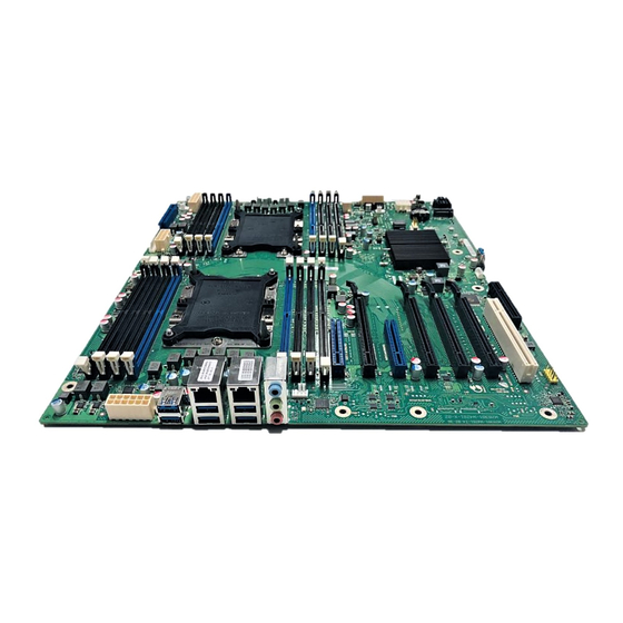
Deutsch - 5 Mainboard D3488 Basierend auf dem Intel® C624 Chipsatz zeichnet sich das D3488 durch eine Reihe hochmoderner Technologien aus. Dazu zählen: Support für die Intel Xeon® Prozessor-Serien im LGA3647 P0 Sockel, multiple PCI-Express Busse, 6-Channel DDR4 Speicherdesign, Onboard PCI-Express Gigabit Ethernet, SATA-Ports und multiple USB 2.0 / 3.0- (Universal Serial Bus) Anschlüsse. -
Page 12: Wichtige Hinweise
6 – Deutsch Mainboard D3488 Wichtige Hinweise Zum Zugriff auf das installierte Mainboard muss das System geöffnet werden. Wie das System auseinandergebaut und wieder zusammengesetzt wird, ist im begleitenden Bedienerhandbuch beschrieben. Zur Vermeidung von Interferenzen müssen die Verbindungskabel für die Peripherie entsprechend abgeschirmt sein. - Page 13 Mainboard D3488 Deutsch - 7 Hinweis für die USA Compliance Information Statement (Declaration of Conformity Procedure) DoC FCC Part 15: Dieses Gerät erfüllt die Anforderungen des Abschnitts 15 der FCC- Bestimmungen. Das Gerät darf nur unter den folgenden Bedingungen betrieben werden: Das Gerät darf keine Störungen verursachen.
-
Page 14: Hardware-Spezifikationen
● Realtek ALC 671 ● Host-basiertes Audio mit 2-Kanal HD Erweiterte Systemüberwachung und - Audio verwaltung ● Fujitsu Technology Solutions System ● Stereokopfhörerausgang (ca. 50 mW bei Management 32 Ω) ● Fujitsu Technology Solutions Thermal ● Sound über interne Systemlautsprecher Management ●... -
Page 15: Systemsicherheitsfunktionen
Mainboard D3488 Deutsch - 9 Kommunikation Energieverwaltung ● Interner Anschluss: 2x USB 3.0, ● Support für ACPI (Speichern im RAM / auf 4x USB 2.0, 1x USB 2.0 Disk) Standardanschluss (für Memorystick) Umweltschutz ● Externer Anschluss (I/O Shield) ● Gesockelte Batterie (recyclingfähig) 6x USB 3.0, Rückseite... -
Page 16: Auswahl Der Korrekten Teile Für Das System
Einzel-/Dualprozessorsystem Das D3488 unterstützt bis zu zwei Intel® Xeon® Prozessoren in einem LGA3647 Sockel. Einzelprozessorsystem: Wenn nur ein Prozessor auf dem D3488 eingesetzt wird, muss dieser im Sockel CPU0 installiert werden. Dualprozessorsystem: Das D3488 unterstützt nur solche dualen Prozessorkonfigurationen, in denen beide Prozessoren mit der gleichen QPI-Frequenz, Core-Frequenz, operieren und über eine gleiche... -
Page 17: Bios Post-Codes (Port 80-Statusanzeigen)
Mainboard D3488 Deutsch - 11 BIOS POST-Codes (Port 80-Statusanzeigen) BIOS-POST-Codes werden auf dem LCD-Display (angeschlossen an den LCD-Anschluss) oder onboard über 8 gelbe LEDs (L0 - L7, L0 ist niedrigste Bit, L7 das höchste) angezeigt. Kontrollpunktbereiche Bereich der Beschreibung Statuscodes 0x01 –... - Page 18 12 – Deutsch Mainboard D3488 0x0A OEM-Initialisierung nach dem Laden des Microcodes 0x0B Cache-Initialisierung SEC-Fehlercodes 0x0C – 0x0D Reserviert für zukünftige AMI-SEC-Fehlercodes 0x0E Microcode nicht gefunden 0x0F Microcode nicht geladen SEC-Beep-Codes Keine SEC-Phase Statuscode Beschreibung Progress-Codes 0x10 PEI-Core wurde gestartet...
- Page 19 Mainboard D3488 Deutsch - 13 0x35 CPU-Post-Memory-Initialisierung. Auswahl des Boot-Strap-Prozessors (BSP) selection 0x36 CPU-Post-Memory-Initialisierung. Initialisierung des System-Management- Modus (SMM) 0x37 Post-Memory-North-Bridge-Initialisierung wurde gestartet 0x38 Post-Memory-North-Bridge-Initialisierung (North-Bridge-Modul-spezifisch) 0x39 Post-Memory-North-Bridge-Initialisierung (North-Bridge-Modul-spezifisch) 0x3A Post-Memory-North-Bridge-Initialisierung (North-Bridge-Modul-spezifisch) 0x3B Post-Memory-South-Bridge-Initialisierung wurde gestartet 0x3C Post-Memory-South-Bridge-Initialisierung (South-Bridge-Modul-spezifisch) 0x3D...
- Page 20 14 – Deutsch Mainboard D3488 S3 Resume-Fehlercodes 0xE8 S3 Resume fehlgeschlagen 0xE9 S3 Resume PPI nicht gefunden 0xEA Fehler S3 Resume Boot Script 0xEB Fehler S3 OS Wake 0xEC-0xEF Reserviert für zukünftige AMI-Fehlercodes Recovery-Progress-Codes 0xF0 Wiederherstellbedingung von Firmware ausgelöst (Auto recovery) 0xF1 Wiederherstellbedingung vom Anwender ausgelöst (Forced recovery)
- Page 21 Mainboard D3488 Deutsch - 15 DXE-Phase Statuscode Beschreibung 0x60 DXE Core wurde gestartet 0x61 NVRAM-Initialisierung 0x62 Installation der South Bridge Runtime Services 0x63 CPU-DXE-Initialisierung wurde gestartet 0x64 CPU-DXE-Initialisierung (CPU-Modul-spezifisch) 0x65 CPU-DXE-Initialisierung (CPU-Modul-spezifisch) 0x66 CPU-DXE-Initialisierung (CPU-Modul-spezifisch) 0x67 CPU-DXE-Initialisierung (CPU-Modul-spezifisch) 0x68 PCI-Host-Bridge-Initialisierung...
- Page 22 16 – Deutsch Mainboard D3488 0x96 PCI Bus Assign Resources 0x97 Console Output Devices Connect 0x98 Console Input Devices Connect 0x99 Super-IO-Initialisierung 0x9A USB-Initialisierung wurde gestartet 0x9B USB Reset 0x9C USB Detect 0x9D USB Enable 0x9E – 0x9F Reserviert für zukünftige AMI-Fehlercodes...
- Page 23 Mainboard D3488 Deutsch - 17 DXE-Fehlercodes 0xD0 CPU-Initialisierungsfehler 0xD1 North-Bridge-Initialisierungsfehler 0xD2 South-Bridge-Initialisierungsfehler 0xD3 Einige Architekturprotokolle sind nicht verfügbar 0xD4 Fehler bei der PCI-Resource-Zuordnung. Keine verfügbaren Resourcen 0xD5 Kein Speicherplatz für Legacy Option ROM 0xD6 Console Output Devices nicht gefunden 0xD7...
-
Page 24: Betrachtungen Zur Stromversorgung
18 – Deutsch Mainboard D3488 Betrachtungen zur Stromversorgung Netzstecker Das D3488 wird mit einem 12 V Netzteil betrieben. 12 V-Netzstecker Pin 9 Pin 1 Pin 7 Pin 1 16-poliger Board-Netzstecker 12-poliger Board-Netzstecker Pin 5 Pin 1 8-poliger Stecker zur Versorgung der Laufwerke... -
Page 25: Installation Des Boards
Pin4: Fan PWM Dieser 4-polige Lüfteranschluss unterstützt die Geschwindigkeitsüberwachung Auf dem D3488 sind sechs 4-polige Lüfteranschlüsse implementiert. Über diese Anschlüsse können Lüfter zur Kühlung von Gehäuse und Prozessor mit dem Motherboard verbunden werden. Kühlende Lüfter tragen zur Systemstabilität und -zuverlässigkeit während der Lebensdauer des Produkts bei. -
Page 26: Frontpanel-Stiftleiste (Intern)
In der Regel verfügt ein Gehäuse über einige Kontroll- oder Signalkabel, die an ein Motherboard für die Festplatten-LED, Netz-LED, den Betriebsschalter und die Reset-Taste angeschlossen werden können. Für solche Zwecke wurde der Frontblendenanschluss auf dem D3488 implementiert. Signal Signal HD-LED +... - Page 27 Mainboard D3488 Deutsch - 21 USB 2.0-Anschluss (intern) Signal Pin 1 VCC AUX (abgesichert) Data negative Data positive USB 3.0-Anschluss (intern) – Intern/Vorderseite Signal Signal Pin 1 Pin 19 VBus USB 3.0 Port 2 RX Neg VBus USB 3.0 Port 2 RX Pos USB 3.0 Port 1 RX Neg...
-
Page 28: Anschlüsse Für Speichergeräte
22 – Deutsch Mainboard D3488 Anschlüsse für Speichergeräte Serial ATA-Anschluss (Intern weiß) POL Signal Transmit data negative Receive data negative Transmit data positive Receive data positive Anschlüsse für Systemüberwachung und -verwaltung SCSI LED-Anschluss (Intern) POL Signal Pin 1 Nicht angeschlossen... -
Page 29: Konfigurations-Jumper Auf Der Frontpanel-Stiftleiste
Mainboard D3488 Deutsch - 23 Konfigurations-Jumper auf der Frontpanel-Stiftleiste Standard-Jumper-Position (Recovery BIOS deaktiviert) Pin 18 Pin 2 Pin 1 Recovery BIOS aktiviert Pin 18 COM1-Anschluss COM1-Anschluss PIN Signal PIN Signal Pin 1 Pin 2 DCD 1 DSR 1 SIN 1... -
Page 30: Speicherinstallation
Speicherinstallation Vor der Installation muss sichergestellt werden, dass der einzusetzende Speicher kompatibel mit dem Motherboard und dem Prozessor ist. Das D3488-Board unterstützt bis zu zwölf 288-polige, 1,2 V / 2,5 V, 2133/2400/2667 MHz DDR4-Module. Hier einige Kernpunkte, die Sie vor der Speicherinstallation auf dem D3488 beachten müssen:... - Page 31 Mainboard D3488 Deutsch - 25 Wenn beide CPU bestückt werden, CPU 0 und CPU 1 wie folgt bestücken: CH-M 1 CH-L 1 CH-C 1 CH-K 1 CH-B 1 CH-K 2 CH-A 1 CH-A 2 CPU 1 LGA3647 CPU 0 LGA3647...
-
Page 32: Vorgehen Bei Der Speicherinstallation
26 – Deutsch Mainboard D3488 Vorgehen bei der Speicherinstallation Bei der Installation von Speichermodulen müssen Sie darauf achten, dass die Module korrekt am Speichersockel ausgerichtet sind. Auf den Speichermodulen sollten sich kleine Kerben befinden, die zu den Kerben im Speichersockel passen. DDR-Module verfügen nur über eine Kerbe, die sich unmittelbar neben dem Mittelpunkt des Moduls/Sockels befindet. - Page 33 Mainboard D3488 Deutsch - 27 Entfernen eines Speichermoduls ► Die Klammern rechts und links am Speichersteckplatz nach außen drücken (1). ► Das Speichermodul aus dem Speichersteckplatz (2) ziehen. Mitunter kann schwierig sein, ein Modul in die korrekte Position zu bringen. Dies ist jedoch nur äußerst selten der Fall.
-
Page 34: Prozessor Tauschen / Zweiten Prozessor Einbauen
28 – Deutsch Mainboard D3488 Prozessor tauschen / zweiten Prozessor einbauen Unterstützte Prozessoren: ● Bis zu zwei Intel® Xeon® CPU (Platinum, Gold, Silver, Bronze) ● Zwei Sockel P0 LGA 3647 ● Max. 165 W ● Beide Prozessoren müssen vom selben Typ sein, d. h. die Anzahl der internen Prozessorkerne ●... -
Page 35: Prozessor Ausbauen
Mainboard D3488 Deutsch - 29 Prozessor ausbauen Die nachfolgenden Schritte müssen nur bei einem Prozessortausch, nicht bei einem Upgrade mit einem zweiten Prozessor durchgeführt werden. ► Rasten Sie den Prozessorrahmen aus (1). Durch Wärmeleitpaste zwischen Prozessor und Kühlkörper kann der Prozessor am Kühlkörper festkleben. -
Page 36: Prozessor In Prozessorrahmen Einbauen
30 – Deutsch Mainboard D3488 ► Drücken Sie die Rastnasen (1) in Pfeilrichtung (2) und heben Sie den Prozessor vom Prozessorrahmen ab (3). ► Entfernen Sie mit einem fusselfreien Tuch eventuell vorhandene Reste von alter Wärmepaste von der Oberfläche des Kühlkörpers und von der glatten Seite des Prozessors. -
Page 37: Wärmeleitpaste Auftragen
Mainboard D3488 Deutsch - 31 ► Halten Sie den Prozessor mit Daumen und Zeigefinger und setzen Sie ihn so in den Prozessorrahmen, dass die Markierung des Prozessors (a) mit der Markierung am Prozessorrahmen (b) von der Lage her übereinstimmt. ►... -
Page 38: Prozessor In Prozessorrahmen Auf Kühlkörper Montieren
32 – Deutsch Mainboard D3488 ► Bringen Sie die oben definierte Menge Wärmeleitpaste in der Mitte des Prozessors auf (1). Bei der Montage des Kühlkörpers wird die Masse gleichmäßig verteilt. Prozessor in Prozessorrahmen auf Kühlkörper montieren ► Falls vorhanden, entfernen Sie die Schutzkappe vom Kühlkörper und verwahren Sie diese. - Page 39 Mainboard D3488 Deutsch - 33 ► Drücken Sie den Prozessorrahmen mit dem Prozessor vorsichtig auf den Kühlkörper. ► Der Prozessorrahmen muss einrasten (1). ► Bauen Sie den Kühlkörper wieder ein. Fujitsu...
-
Page 40: Installation Von Add-In-Karten
34 – Deutsch Mainboard D3488 Installation von Add-In-Karten Prüfen Sie vor der Installation von Add-In-Karten, ob diese vollständig kompatibel mit dem Motherboard sind. SLOT7 PCle x8 CPU1 (GEN3) SLOT6 PCle x16 CPU0 (GEN3) SLOT5 PCle x8 CPU0 (GEN3) SLOT4 PCle x16 CPU1 (GEN3) -
Page 41: Anschließen Von Externen Geräten
Mainboard D3488 Deutsch - 35 Anschließen von externen Geräten Das Anschließen von externen Geräten an das Motherboard ist eine einfache Aufgabe. Zu den Standardkomponenten, die üblicherweise an das Motherboard angeschlossen werden, zählen Tastatur-, Maus- und Druckerkabel. In nachstehendem Diagramm wird der ATX-Port-Stack für... -
Page 42: Austauschen Der Lithium-Batterie
36 – Deutsch Mainboard D3488 Austauschen der Lithium-Batterie Die installierte Lithium-Batterie versorgt den CMOS-Speicher mit Strom, damit die Systeminformationen permanent gespeichert bleiben. Wenn die Batterie leer oder fast leer ist, wird dem Benutzer eine entsprechende Fehlermeldung angezeigt. Die Lithium-Batterie muss dann ausgetauscht werden. -
Page 43: Bios-Update
Deutsch - 37 BIOS-Update Wann sollte ein BIOS-Update durchgeführt werden? Fujitsu Technology Solutions stellt neue BIOS-Versionen zur Verfügung, um die Kompatibilität zu neuen Betriebssystemen, zu neuer Software oder zu neuer Hardware zu gewährleisten. Außerdem können neue BIOS-Funktionen integriert werden. Ein BIOS-Update sollte auch immer dann durchgeführt werden, wenn ein Problem besteht, das sich durch neue Treiber oder neue Software nicht beheben lässt. -
Page 44: Glossar
38 – Deutsch Mainboard D3488 Glossar Die nachfolgend aufgelisteten Begriffe und Abkürzungen stellen nur eine Auswahl der kompletten Liste mit allgemeinen technischen Begriffen und Abkürzungen dar. Nicht alle hier aufgelisteten technischen Begriffe und Abkürzungen beziehen sich auf das hier beschriebene Motherboard. - Page 45 Mainboard D3488 English - 1 Content Overview Mainboard D3488 ....................... 3 Mainboard D3488..........................5 Notational conventions ......................... 5 Important notes............................. 6 Information about boards ......................6 Hardware Specifications........................8 System security features ........................9 Basic security features ......................... 9 Trusted Platform Module (TPM) ....................9 Choose Proper Parts for Your System ...................
- Page 46 Trademarks Fujitsu and the Fujitsu logo are registered trademarks of Fujitsu Limited in Japan and in other countries. Intel is a trademark of the Intel Corporation in the USA and/or other countries.
-
Page 47: Overview Mainboard D3488
Mainboard D3488 English - 3 Overview Mainboard D3488 FAN 2 FAN 1 SLOT8 PCIe x8 Gen 3 PC 2009 CH-M 1 POWER POWER CH-L 1 CH-K 1 CH-C 1 POWER CH-K 2 CH-B 1 CH-A 1 CH-A 2 USB 3.0 2x USB 3.0... - Page 48 Mainboard D3488 4 – English Risk of Explosion if battery is replaced by an incorrect type. Dispose of used batteries according to the instructions. Il y a risque d’explosion si la batterie est remplacée par une batterie de type incorrect.
-
Page 49: Mainboard D3488
English - 5 Mainboard D3488 Based on the Intel® C624 chipset, the D3488 is characterised by a range of ultra-modern technologies. These include: Support for the Intel Xeon® processor series in the LGA3647 P0 socket, multiple PCI-Express buses, 6 Channel DDR4 memory design, Onboard PCI-Express Gigabit Ethernet, SATA ports and multiple USB 2.0 / 3.0 (Universal Serial Bus) ports. -
Page 50: Important Notes
Mainboard D3488 6 – English Important notes With the mainboard installed you must open the system to access the mainboard. How to dismantle and reassemble the system is described in the operating manual accompanying the system. Connecting cables for peripherals must be adequately shielded to avoid interference. - Page 51 Mainboard D3488 English - 7 Notice for the USA Compliance Information Statement (Declaration of Conformity Procedure) DoC FCC Part 15: This device complies with part 15 of the FCC Rules: Operation is subject to the following conditions: This device may not cause harmful interference, and This device must accept any interference received including interference that may cause undesired operation.
-
Page 52: Hardware Specifications
Audio Advanced system monitoring and ● Realtek ALC 671 management ● Host based Audio with 2-channel HD ● Fujitsu Technology Solutions System Audio Management ● Stereo Head-Phone Out (approx. 50 mW ● Fujitsu Technology Solutions Thermal at 32 Ω) Management ●... -
Page 53: System Security Features
Mainboard D3488 English - 9 Communication Environmental protection ● Internal connector: 2x USB 3.0, ● Socketed battery (recyclable) 4x USB 2.0, 1x USB 2.0 standard Form factor, slots, compatibility list connector (for memory stick) ● Form factor: AT03 extended ●... -
Page 54: Choose Proper Parts For Your System
Single/Dual Processor System The D3488 supports up to two Intel® Xeon® processors in an LGA3647 socket. Single Processor System: When only installing a single processor on D3488, the processor must be installed in the CPU0 socket. Dual Processor System: D3488 supports dual processor configurations only in which both processors operate with the same QPI frequency, core frequency, and have the same internal cache sizes. -
Page 55: Bios Post-Codes (Port 80 Status Indicators)
Mainboard D3488 English - 11 BIOS POST-Codes (Port 80 status indicators) BIOS-POST codes are visible on the LCD-display (connected to the LCD-connector) or onboard via 8 yellow LEDs (L0-L7, L0 is the lowest bit, L7 the highest). Checkpoint Ranges Status Code... - Page 56 Mainboard D3488 12 – English 0x0A OEM initialization after microcode loading 0x0B Cache initialization SEC Error Codes 0x0C – 0x0D Reserved for future AMI SEC error codes 0x0E Microcode not found 0x0F Microcode not loaded SEC Beep Codes None SEC Phase...
- Page 57 Mainboard D3488 English - 13 0x35 CPU post-memory initialization. Boot Strap Processor (BSP) selection 0x36 CPU post-memory initialization. System Management Mode (SMM) initialization 0x37 Post-Memory North Bridge initialization is started 0x38 Post-Memory North Bridge initialization (North Bridge module specific) 0x39...
- Page 58 Mainboard D3488 14 – English 0xEA S3 Resume Boot Script Error 0xEB S3 OS Wake Error 0xEC-0xEF Reserved for future AMI error codes Recovery Progress Codes 0xF0 Recovery condition triggered by firmware (Auto recovery) 0xF1 Recovery condition triggered by user (Forced recovery)
- Page 59 Mainboard D3488 English - 15 0x68 PCI host bridge initialization 0x69 North Bridge DXE initialization is started 0x6A North Bridge DXE SMM initialization is started 0x6B North Bridge DXE initialization (North Bridge module specific) 0x6C North Bridge DXE initialization (North Bridge module specific)
- Page 60 Mainboard D3488 16 – English 0xA2 IDE Detect 0xA3 IDE Enable 0xA4 SCSI initialization is started 0xA5 SCSI Reset 0xA6 SCSI Detect 0xA7 SCSI Enable 0xA8 Setup Verifying Password 0xA9 Start of Setup 0xAA Reserved for ASL (see ASL Status Codes section below)
- Page 61 Mainboard D3488 English - 17 0xDB Flash update is failed 0xDC Reset protocol is not available DXE Beep Codes # of Beeps Description Invalid password Some of the Architectural Protocols are not available No Console Output Devices are found No Console Input Devices are found...
-
Page 62: Power Supply Considerations
Mainboard D3488 18 – English Power Supply Considerations Power Connectors The D3488 is operated with a 12 V power supply. 12 V Power Connectors Pin 9 Pin 1 Pin 7 Pin 1 16-pin board power connector 12-pin board power connector... -
Page 63: Board Installation
Pin4: Fan PWM This 4-pin fan connector supports tachometer monitoring. There are six 4-pin fan connectors on D3488. Use these connectors to connect chassis and processor cooling fans to your motherboard. Cooling fans can keep the system stable and reliable for its product’s life. -
Page 64: Front Panel Pin Connector (Internal)
Normally, a chassis has some control or signal wires can be connected onto a motherboard for hard drive LED, Power LED, power button, and reset button; The front panel connector has been implemented on D3488 for such purposes. PIN Signal... - Page 65 Mainboard D3488 English - 21 USB 2.0 port (internal) PIN Signal Pin 1 VCC AUX (safe mode) Data negative Data positive USB 3.0 port (internal) – Internal/Front PIN Signal Signal Pin 1 Pin 19 VBus USB 3.0 Port 2 RX Neg VBus USB 3.0 Port 2 RX Pos...
-
Page 66: Ports For Memory Devices
Mainboard D3488 22 – English Ports for memory devices Serial ATA port (internal, white) POL Signal Transmit data negative Receive data negative Transmit data positive Receive data positive System monitoring and management connectors SCSI LED connector (Internal) Signal Pin 1... -
Page 67: Com1 Ports
Mainboard D3488 English - 23 COM1 Ports COM1 port PIN Signal PIN Signal Pin 1 Pin 2 DCD 1 DSR 1 SIN 1 RTS 1 SOUT 1 CTS 1 DTR 1 RI 1 Fujitsu... -
Page 68: Installing The Memory
Before attempting to install any memory, make sure that the memory you have is compatible with the motherboard as well as the processor. The D3488 board supports up to twelve 288-pin 1.2 V / 2.5 V, 2133/2400/2667 MHz DDR4 modules. - Page 69 Mainboard D3488 English - 25 If both CPUs are equipped, equip CPU 0 and CPU 1 as follows: CH-M 1 CH-L 1 CH-C 1 CH-K 1 CH-B 1 CH-K 2 CH-A 1 CH-A 2 CPU 1 LGA3647 CPU 0 LGA3647...
-
Page 70: Memory Installation Procedure
Mainboard D3488 26 – English Memory Installation Procedure When installing memory modules, make sure the modules align properly with the memory socket. There should be keys (small indents) on your memory modules that fit according to the keys in the memory socket. - Page 71 Mainboard D3488 English - 27 Removing a memory module ► Push the clips on the right and left of the memory slot outward (1). ► Pull the memory module out of the memory slot (2). When installing memory, a module may require a considerable amount of force to seat properly, although this is very rare.
-
Page 72: Replace The Processor / Install A Second Processor
Mainboard D3488 28 – English Replace the processor / install a second processor Processors supported ● Up to two Intel® Xeon® CPUs (Platinum, Gold, Silver, Bronze) ● Two bases, type P0 LGA 3647 ● Maximum power: 165 W ● Both processors must be of the same type, i.e. the number of the internal processor cores, ●... -
Page 73: Remove The Processor
Mainboard D3488 English - 29 Remove the processor The following steps only need to be completed when a processor is being replaced, and not with an upgrade when a second processor is fitted. ► Release the processor frame from its locking slots (1). -
Page 74: Fit The Processor Into The Processor Frame
Mainboard D3488 30 – English ► Press the latches (1) in the direction of the arrow (2) and lift the processor out of the processor frame (3). ► Use a lint-free cloth to remove any traces of old heat-conducting paste from the surface of the heat sink and from the flat side of the processor. -
Page 75: Apply The Heat-Conducting Paste
Mainboard D3488 English - 31 ► The processor must lock into place (1). Apply the heat-conducting paste Do not mix different types of heat-conducting paste. If the kit for a processor upgrade or a processor replacement contains a new heat sink, a thin layer of heat-conducting paste will already be applied to the underside of the heat sink. -
Page 76: Fit The Processor In The Processor Frame On The Heat Sink
Mainboard D3488 32 – English ► Apply the amount of heat-conducting paste defined above on the middle of the processor (1). When installing the heat sink, the mass must be evenly distributed. Fit the processor in the processor frame on the heat sink ►... - Page 77 Mainboard D3488 English - 33 ► Press the processor frame with the processor carefully onto the heat sink. ► The processor frame must lock into place (1). ► Install the heat sink again. Fujitsu...
-
Page 78: Installing Add-In Cards
Mainboard D3488 34 – English Installing Add-In Cards Before installing add-in cards, please check if they are fully compatible with your motherboard. SLOT7 PCle x8 CPU1 (GEN3) SLOT6 PCle x16 CPU0 (GEN3) SLOT5 PCle x8 CPU0 (GEN3) SLOT4 PCle x16 CPU1 (GEN3) -
Page 79: Connecting External Devices
Mainboard D3488 English - 35 Connecting External Devices Connecting external devices to the motherboard is an easy task. The standard devices you should expect to plug into the motherboard are keyboards, mouse, and printer cables. The following diagram will detail the ATX port stack for the following board:... -
Page 80: Replacing Lithium Battery
Mainboard D3488 36 – English Replacing lithium battery In order to permanently save the system information, a lithium battery is installed to provide the CMOS-memory with a current. A corresponding error message notifies the user when the charge is too low or the battery is empty. The lithium battery must then be replaced. -
Page 81: Bios Update
English - 37 BIOS update When should a BIOS update be carried out? Fujitsu Technology Solutions makes new BIOS versions available to ensure compatibility to new operating systems, new software or new hardware. In addition, new BIOS functions can also be integrated. -
Page 82: Glossary
Mainboard D3488 38 – English Glossary The technical terms and abbreviations given below represent only a selection of the full list of common technical terms and abbreviations. Not all technical terms and abbreviations listed here are valid for the described mainboard.
Need help?
Do you have a question about the D3488 and is the answer not in the manual?
Questions and answers