
Related Manuals for Fujitsu D3031


Summary of Contents for Fujitsu D3031
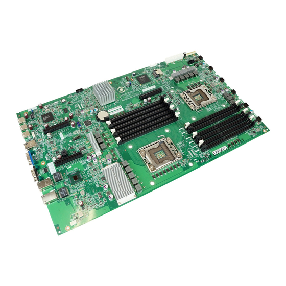
- Page 1 Technical Manual - English System Board D3031 for PRIMERGY RX200 S6 Technical Manual Edition August 2010...
- Page 2 – The contents of this manual may be revised without prior notice. – Fujitsu assumes no liability for damages to third party copyrights or other rights arising from the use of any information in this manual. – No part of this manual may be reproduced in any form without the prior written permission of Fujitsu.
- Page 3 It has not been designed or manufactured for uses which demand an extremely high level of safety and carry a direct and serious risk to life or body if such safety cannot be ensured. Technical Manual D3031 (RX200 S6)
- Page 4 (hereafter, "high safety use"). Customers should not use this product for high safety use unless measures are in place for ensuring the level of safety demanded of such use. Please consult the sales staff of Fujitsu if intending to use this product for high safety use.
- Page 5 Only for the Japanese market: Although described in this manual, some sections do not apply to the Japanese market. These options and routines include: – CSS (Customer Self Service) – Replacing the lithium battery Technical Manual D3031 (RX200 S6)
- Page 6 Technical Manual D3031 (RX200 S6)
-
Page 7: Table Of Contents
Switches ......35 Replacing the lithium battery ....37 Technical Manual D3031 (RX200 S6) - Page 8 Contents Technical Manual D3031 (RX200 S6)
-
Page 9: Introduction
DVDs (see Installation DVD of ServerView Suite - ServerView Software Products). You will find further information about the BIOS setup in the "D3031 BIOS Setup Utility for PRIMERGY RX200 S6" manual. - Page 10 Introduction Technical Manual D3031 (RX200 S6)
-
Page 11: Important Information
Information on which system expansions are approved for installation can be obtained from our customer service center or your sales outlet. The warranty expires if the device is damaged during the installation or replacement of system expansions. Technical Manual D3031 (RX200 S6) - Page 12 (this information doesn’t apply to the Japanese market). It is essential to observe the instructions in the chapter "Replacing the lithium battery". Technical Manual D3031 (RX200 S6)
- Page 13 Do not touch any connectors or conduction paths on an ESD. Place all the components on a pad which is free of electrostatic charge. For a detailed description of how to handle ESD components, see the relevant European or international standards (EN 61340-5-1, ANSI/ESD S20.20). Technical Manual D3031 (RX200 S6)
-
Page 14: Ce Certificate Of Conformity
The board complies with the requirements of the EC directives 2004/108/EC regarding "Electromagnetic Compatibility" and 2006/95/EC "Low Voltage Directive". This is indicated by the CE marking (CE = Communauté Européenne). Compliance was tested in a typical PRIMERGY configuration. Technical Manual D3031 (RX200 S6) -
Page 15: Environmental Protection
Environmental protection Environmental protection Environmentally-friendly product design and development This product has been designed in accordance with the Fujitsu standard for "environmentally friendly product design and development". This means that key factors such as durability, selection and labeling of materials, emissions, packaging, ease of dismantling and recycling have been taken into account. - Page 16 Details regarding the return and recycling of devices and consumables within Europe can also be f o und in the "Retur ning used devices" manual, via your local Fujitsu branch or from our recycling center in Paderborn: Fujitsu Technology Solutions...
-
Page 17: Features
– maximum 192 GB (with RDIMMs) or 24 GB (with UDIMMs) of memory – ECC multiple bit error detection and single bit error correction – memory scrubbing function – Single Device Data Correction (SDDC) function (Chipkill™), only with RDIMMs – memory mirroring function – memory sparing function Technical Manual D3031 (RX200 S6) - Page 18 – 1x RJ45 management LAN connector – Front side – 3x USB connectors – 1x video connector (VGA) PCI slots – 2x PCI Express x8 expansion slots – 1x PCI Express x4 expansion slot (mechanical x8) Technical Manual D3031 (RX200 S6)
- Page 19 Battery in holder for recycling Form factor 290 x 485 mm CSS (Customer Self Service) This system board supports the CSS functionality. You will find a description of CSS functionality in the operating manual of your server. Technical Manual D3031 (RX200 S6)
- Page 20 TPM or the system board is faulty you will not be able to access your data. – If a failure occurs, please inform your service about the TPM activation before it takes any action, and be prepared to provide them with your backup copies of the TPM content. Technical Manual D3031 (RX200 S6)
-
Page 21: Main Memory
Figure 2: Slots of the main memory – Minimum main memory configuration is 1 DIMM with Independent Channel Mode. – It is possible to mix memory modules with different clock rates. The lowest clock rate will be applied to the system. Technical Manual D3031 (RX200 S6) -
Page 22: Modes Of Operation
– Allows population of all channels in any order. Related to the channels (A-F) DIMM1 must be populated first. – Works with DIMMs of different clock rates and applies the lowest clock rate. – Works with UDIMMs as well as RDIMMs. Technical Manual D3031 (RX200 S6) - Page 23 – Requires identical modules on all channels of each bank per CPU. – One third of the capacity is used as spare range — this means the main memory for the applications is reduced to two third. – RDIMMs are supported. Technical Manual D3031 (RX200 S6)
-
Page 24: Lv-Dimm Support
800 MHz; operating voltage is set to 1.35 V "Performance" speed is set to 1333 MHz; operating voltage is set to 1.5 V The speed and operating voltage settings apply to all six sockets of one CPU in common. Technical Manual D3031 (RX200 S6) -
Page 25: Pci Slots
– Riser card with one standard half length PCI Express expansion x8 slot – Riser card with one low-profile half length PCI Express expansion x8 slot – Riser card with one low-profile half length PCI Express expansion x4 slot (mechanically: x8), reserved for modular RAID option. Technical Manual D3031 (RX200 S6) -
Page 26: Screen Resolution
24 bit 1280x1024 24 bit 1600x1200 16 bit If you are using an external graphic controller, you will find details of supported screen resolutions in the operating manual or technical manual supplied with the graphic controller. Technical Manual D3031 (RX200 S6) -
Page 27: Temperature / System Monitoring
All monitored events of the system board are signalized via the Global Error LED and recorded in the System Event Log. The events can be retrieved in the BIOS Setup or via the ServerView Operations Manager. Technical Manual D3031 (RX200 S6) -
Page 28: Connectors And Indicators
Features Connectors and indicators Connectors and indicators 3.6.1 System board Figure 5: Internal connectors of the system board D3031 Technical Manual D3031 (RX200 S6) - Page 29 SATA1 HDD connector (4 ports) CN13 PSU main connector SATA2 SATA ODD connector JP16 Connector for external generation of a system reset Front panel connector JP4, System fan connectors JP7, JP10, JP11, JP12 CN30 Connector for TPM Technical Manual D3031 (RX200 S6)
- Page 30 Features Connectors and indicators Figure 6: Indicators on the system board and CSS indicate button Technical Manual D3031 (RX200 S6)
- Page 31 E - CPU orange on CPU failure F - system fans green on fan okay orange on fan failure G - memory orange on memory module failure H - iRMC S2 green flashing iRMC S2 okay Technical Manual D3031 (RX200 S6)
-
Page 32: Connector Panel
(iRMC S2) and is prepared for operation with the Remote Management. Optionally LAN connector 1 can also be used for iRMC S2 server management. Each LAN connector has two LEDs which display the speed of the connection and its status: Technical Manual D3031 (RX200 S6) - Page 33 Flashes yellow in the event of a LAN transfer rate of (system LAN) 1 Gbit/s Steady green signal in the event of a LAN transfer rate of 100 Mbit/s. Remains dark in the event of a LAN transfer rate of 10 Mbit/s. Technical Manual D3031 (RX200 S6)
-
Page 34: Settings
Figure 9: Jumpers and switches 3.7.1 Jumpers The default setting for all jumpers is position 1-2. Clear CMOS jumper - JP2 Jumper Pos. Description Normal, not clear CMOS settings (default setting). Clear CMOS settings and restore default values (hardware). Technical Manual D3031 (RX200 S6) - Page 35 Ê Press [F9] to set the system defaults. Ê Press [F10] to save your changes and to exit the Setup Utility. Protect RTC jumper - JP5 Jumper Pos. Description Normal operation (default setting) Clear ME_RTC REG Technical Manual D3031 (RX200 S6)
-
Page 36: Switches
Password enabled S1-3 BIOS write- BIOS can only be read protect BIOS can both be read and written to S1-4 CMOS clear Clear CMOS settings (software) and restore system defaults Normal CMOS settings Technical Manual D3031 (RX200 S6) -
Page 37: Replacing The Lithium Battery
Ê Press the locking spring into direction of the arrow (1), so that the lithium battery jumps out of its socket. Ê Remove the battery (2). Ê Insert a new lithium battery of the same type into the socket (3) and (4). Technical Manual D3031 (RX200 S6) - Page 38 Replacing the lithium battery Technical Manual D3031 (RX200 S6)
Need help?
Do you have a question about the D3031 and is the answer not in the manual?
Questions and answers