Sign In
Upload
Manuals
Brands
Eurotherm Manuals
Controller
Invensys Mini8
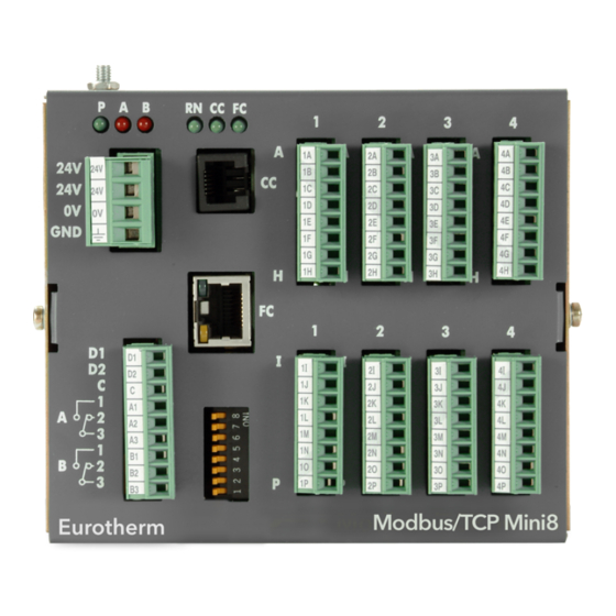
Eurotherm Invensys Mini8 Manuals
Manuals and User Guides for Eurotherm Invensys Mini8. We have
3
Eurotherm Invensys Mini8 manuals available for free PDF download: User Manual, Engineering Manual, Installation And Wiring Instructions
Eurotherm Invensys Mini8 User Manual (343 pages)
Multi-loop Process Controller
Brand:
Eurotherm
| Category:
Controller
| Size: 7 MB
Table of Contents
Table of Contents
3
Warning Back up Battery
10
Mini8 Controller - Multi-Loop Process Controller
12
Chapter 1 Installation
12
What Instrument Do I Have
12
Mini8 Controller Ordering Code
13
How to Install the Controller
14
Dimensions
14
To Install the Controller
14
Environmental Requirements
14
Electrical Connections - Common to All Instruments
15
Power Supply
15
Fixed IO Connections
16
Digital Communications Connections
16
Configuration Port (CC)
16
Screened Communications Cables
16
Electrical Connections for Modbus
17
Modbus Connectors
17
Rs485
17
Direct Connection - Master and One Slave
18
RS485 to RS232 Converter
19
One Master, Multiple Slaves Short Network
20
Wiring Connections for Modbus Broadcast Communications
21
Electrical Connections for Devicenet / Canopen
22
Devicenet Connector
22
Network Length
23
Typical Devicenet / Canopen Wiring Diagram
23
Electrical Connections for Enhanced Devicenet Interface
24
Enhanced Devicenet Connector
24
Switches and LED Indicators
24
Electrical Connections for Profibus DP
25
Profibus Interface (D-Type Connector)
25
Profibus Interface (RJ45 Connector)
25
Electrical Connections for Ethernet (Modbus TCP)
26
Connector: RJ45
26
Electrical Connections for Ethernet/Ip
27
Connector: RJ45
27
Electrical Connections for Ethercat
28
Connector: RJ45
28
Electrical Connections for Thermocouple Input TC4 and TC8
29
Electrical Connections for RTD
29
Electrical Connections for Logic Input DI8
30
Electrical Connections for Logic Output DO8
30
Electrical Connections for Inductive Loads
30
Electrical Connections for Relay Output RL8
31
Electrical Connections for Analogue Output AO4 and AO8
31
Electrical Connections for Current Transformer Input Module CT3
32
Adding or Replacing an IO Module
33
Chapter 2 Mini8 Controller Led Indicators
34
Status Indication for Enhanced Devicenet
35
Module Status Indication
35
Network Status Indication
35
Status Indication for Ethernet/Ip
36
Module Status Indication
36
Network Status Indication
36
Status Leds for Ethercat
37
OP' - Mini8 Run Status Indication
37
CC' - Configuration Port Status Indication
37
RUN' - Ethercat Slave Run Status Indication
37
ERR' - Error Status Indication
37
Chapter 3 Using the Mini8 Controller
38
Itools
38
Itools OPC Open Server
38
Modbus, Single Register, SCADA Addressing
38
Modbus (Floating Point)
39
Fieldbus
39
Ethernet (Modbus TCP)
39
Mini8 Controller Execution
39
The Itools Operator Interface
40
Scanning
40
Browsing and Changing Parameter Values
40
Recipe Editor
42
Recipe Menu Commands
42
Opcscope
43
OPC Scope List Window Context Menu
44
OPC Scope Chart Window
44
OPC Server
46
Chapter 4 Configuration Using Itools
47
Configuration
47
Connecting a PC to the Mini8 Controller
47
Configuration Cable and Clip
47
Cloning
48
Configuring the Mini8 Controller
49
Function Blocks
49
Soft Wiring
50
Simple Worked Example
51
The I/O
51
Wiring
54
Graphical Wiring Editor
57
Graphical Wiring Toolbar
58
Function Block
58
Wire
58
Block Execution Order
58
Using Function Blocks
58
Tooltips
59
Function Block State
60
Using Wires
61
Using Comments
62
Using Monitors
63
Downloading
63
Selections
63
Colours
64
Diagram Context Menu
64
Wiring Floats with Status Information
65
Edge Wires
66
Chapter 5 Mini8 Controller Overview
67
Complete List of Function Blocks
68
Chapter 6 Access Folder
69
Chapter 7 Instrument Folder
70
Instrument / Enables
70
Instrument Options
71
Instrument / Instinfo
71
Instrument / Diagnostics
72
Chapter 8 I/O Folder
74
Module ID
74
Modules
74
Logic Input
75
Logic Input Parameters
75
Logic Output
76
Logic out Parameters
76
Logic Output Scaling
77
Example: to Scale a Proportioning Logic Output
77
Relay Output
78
Relay Parameters
78
Thermocouple Input
79
Thermocouple Input Parameters
79
Linearisation Types and Ranges
81
CJC Type
81
Sensor Break Value
82
Fallback
82
User Calibration (Two Point)
83
PV Offset (Single Point)
83
Using TC4 or TC8 Channel as a MV Input
84
Resistance Thermometer Input
85
RT Input Parameters
85
Linearisation Types and Ranges
86
Using RT4 as Ma Input
86
Analogue Output
87
Example: 4 to 20Ma Analogue Output
87
Fixed IO
88
Current Monitor
89
Current Measurement
89
Single Phase Configurations
90
Three Phase Configuration
92
Parameter Configuration
93
Commissioning
94
Calibration
96
Chapter 9 Alarms
97
Further Alarm Definitions
97
Analogue Alarms
98
Analogue Alarm Types
98
Digital Alarms
99
Digital Alarm Types
99
Alarm Outputs
99
How Alarms Are Indicated
99
To Acknowledge an Alarm
99
Alarm Parameters
100
Example: to Configure Alarm 1
101
Digital Alarm Parameters
102
Example: to Configure Digalarm 1
102
Alarm Summary
103
Alarm Log
105
Chapter 10 Bcd Input
106
BCD Parameters
106
Example: to Wire a BCD Input
107
Chapter 11 Digital Communications
108
Configuration Port (CC)
108
Configuration Communications Parameters
108
Field Communications Port (FC)
109
Communications Identity
109
Modbus
110
Modbus Connections
110
Modbus Address Switch
110
Baud Rate
110
Parity
110
RX/TX Delay Time
110
Modbus Broadcast Master Communications
111
Mini8 Controller Broadcast Master
111
Modbus Parameters
112
Switch Position in Itools
113
Devicenet Parameters
114
Devicenet
113
Enhanced Devicenet Interface
113
Address Switch
113
Baud Switch
113
Canopen
115
Instrument Setup
115
Mini8 Controller Canopen Features
115
Communication Interface
116
Network Management (NMT)
117
Device Profile DS-404
118
Default Pdos
118
Enabling and Disabling PDO Communications
121
Changing PDO Mapping
121
Remapping over the Network
124
Enabling & Disabling PDO Change of State Transmission
126
General Communication Objects
126
Profibus
131
Profibus Parameters
131
Ethernet (Modbus TCP)
132
Instrument Setup
132
Unit Identity
132
Dynamic Host Configuration Protocol (DHCP) Settings
132
Itools Setup
133
Ethernet Parameters
134
Ethernet/Ip
135
Feature Switch
135
Configuration Using Itools
135
Ethernet/Ip Parameters
136
Input Definition Table
137
Output Definition Table
138
Requested Packet Interval
138
Example - Connect Mini8 Controller to Allen-Bradley PLC Via Ethernet/Ip
139
Installation
139
Setting up the Link between Windows and the Plc Network
139
Updating Firmware
141
Completing the Link
141
Creating a Network Scanner
143
Create or Load a Mini8 Controller Configuration
146
Run Mode
147
Monitor Parameters
148
Status Indicators
148
11.12.10 Mini8 Controller on an Ethernet/Ip Network
149
11.12.11 Troubleshooting
150
Ethercat
151
Ethercat-To-Modbus Interface
151
Ethercat Feature Switch
151
Ethercat Parameters
152
Parameter Pick List and IO Mapping
153
File over Ethercat
154
To Produce a UID File
155
Precautions
155
Trademark
156
Chapter 12 Counters, Timers, Totalisers, Rt Clock
157
Counters
157
Counter Parameters
158
Timers
159
Timer Types
159
On Pulse Timer Mode
159
On Delay Timer Mode
160
One Shot Timer Mode
161
Minimum on Timer or Compressor Mode
162
Timer Parameters
163
Totalisers
164
Totaliser Parameters
165
Real Time Clock
166
Real Time Clock Parameters
166
Chapter 13 Applications
167
Humidity
167
Overview
167
Temperature Control of an Environmental Chamber
167
Humidity Control of an Environmental Chamber
167
Humidity Parameters
168
Zirconia (Carbon Potential) Control
169
Temperature Control
169
Carbon Potential Control
169
Sooting Alarm
169
Automatic Probe Cleaning
169
Endothermic Gas Correction
169
Clean Probe
169
Probe Status
169
Zirconia Parameters
170
Chapter 14 Input Monitor
172
Description
172
Maximum Detect
172
Minimum Detect
172
Time above Threshold
172
Input Monitor Parameters
173
Chapter 15 Logic and Maths Operators
174
Logic Operators
174
Logic 8
174
Input Logic Operations
175
Logic Operator Parameters
176
Eight Input Logic Operators
177
Maths Operators
178
Math Operations
179
Math Operator Parameters
180
Sample and Hold Operation
181
Multiple Input Operator Block
182
Cascaded Operation
183
Fallback Strategy
183
Multiple Input Operator Block Parameters
184
Eight Input Analog Multiplexers
185
Multiple Input Operator Parameters
185
Fallback
185
Chapter 16 Input Characterisation
186
Input Linearisation
186
Compensation for Sensor Non-Linearities
187
Input Linearisation Parameters
188
Polynomial
189
Chapter 17 Load
191
Load Parameters
191
Chapter 18 Control Loop Set up
192
What Is a Control Loop
192
Loop Parameters - Main
193
Loop Set up
194
Types of Control Loop
194
PID Control
195
Proportional Band
196
Integral Term
196
Derivative Term
197
High and Low Cutback
198
Integral Action and Manual Reset
198
Relative Cool Gain
198
Loop Break
199
Cooling Algorithm
199
Gain Scheduling
200
PID Parameters
201
Loop Response
202
Initial Settings
202
Multi-Zone Applications
203
Automatic Tuning
204
Tune Parameters
205
To Auto Tune a Loop - Initial Settings
205
To Start Autotune
206
Autotune and Sensor Break
206
Autotune and Inhibit
206
Autotune and Gain Scheduling
206
Autotune from below SP - Heat/Cool
207
Autotune from below SP - Heat Only
208
Autotune at Setpoint - Heat/Cool
209
Failure Modes
210
Manual Tuning
211
Manually Setting Relative Cool Gain
211
Manually Setting the Cutback Values
212
Setpoint Function Block
213
SP Tracking
214
Manual Tracking
214
Rate Limit
214
Setpoint Parameters
214
Setpoint Limits
216
Setpoint Rate Limit
216
Setpoint Tracking
217
Manual Tracking
217
Output Function Block
218
Output Limits
221
Output Rate Limit
222
Sensor Break Mode
222
Forced Output
222
Feedforward
223
Effect of Control Action, Hysteresis and Deadband
224
Chapter 19 Setpoint Programmer
225
Introduction
225
Time to Target Programmer
225
Ramp Rate Programmer
226
Mini8 Controller Programmer Block(S)
226
Segment Types
227
Rate
227
Dwell
227
Step
227
Time
227
Goback
227
Wait
228
End
228
Output Events
229
Digital Events
229
PV Event & User Value
230
Time Event
231
Holdback
233
Guaranteed Soak
233
PID Select
234
Program Cycles
234
Servo
234
Power Fail Recovery
235
Ramp (Power Fail During Dwell Segments.)
235
Ramp (Power Fail During Ramp Segments)
235
Ramp (Power Fail During Time-To-Target Segments)
235
To Run, Hold or Reset a Program
236
Run
236
Reset
236
Hold
236
Skip Segment
236
Advance Segment
237
Fast
237
PV Start
237
Configuring the Programmer
238
Programmer Run Status
241
Creating a Program
242
Program Editor
242
Analog View
243
Digital View
245
Saving & Loading Programs
245
Printing a Program
246
Wiring the Programmer Function Block
247
Chapter 20 Switch over
249
Switch over Parameters
250
Chapter 21 Transducer Scaling
251
Auto-Tare Calibration
251
Load Cell
252
Comparison Calibration
252
Transducer Scaling Parameters
252
Parameter Notes
254
Tare Calibration
254
Load Cell
255
Comparison Calibration
255
Chapter 22 User Values
256
User Value Parameters
256
Chapter 23 Calibration
257
TC4 / TC8 User Calibration
257
Set up
257
Zero Calibration
257
Voltage Calibration
257
CJC Calibration
257
Sensor-Break Limit Check
257
To Return to TC4/TC8 Factory Calibration
258
RT4 User Calibration
258
Set up
258
Calibration
258
To Return to RT4 Factory Calibration
258
Calibration Parameters
259
Chapter 24 Oem Security
260
Introduction
260
Using OEM Security
260
Step 1 - View Itools OPC Server
261
Step 2 - Create Custom Tags
262
Step 3 - Activate OEM Security
264
Step 4 - Deactivate OEM Security
265
Erasing Memory
265
Appendix A Modbus Scada Table
266
Comms Table
266
SCADA Table
266
Programmer Address Ranges - Decimal
296
Version 2.XX Programmer Addresses - Hexadecimal
303
Appendix B Devicenet Parameter Tables
310
IO Re-Mapping Object
310
Application Variables Object
311
Table Modification
315
Appendix C Canopen Parameter Tables
316
Manufacturer Object - Pick List
316
Version 1.XX Parameter Tables
320
Configuring the Programmer (V1.XX)
320
To Select, Run, Hold or Reset a Program (V1.XX)
321
Creating a Program (V1.XX)
321
To Select, Run, Hold or Reset a Program (Version 1.XX)
322
Appendix D Version 1.XX Programmer
320
SCADA Addresses for Programmer Version 1.XX
322
Appendix E Safety and Emc Information
328
Appendix F Technical Specification
331
Environmental Specification
331
Network Communications Support
331
Configuration Communications Support
331
Fixed I/O Resources
332
TC8 8-Channel and TC4 4-Channel TC Input Card
332
DO8 8-Channel Digital Output Card
333
RL8 8-Channel Relay Output Card
333
CT3 3-Channel Current-Transformer Input Card
333
Load Failure Detection
333
DI8 8-Channel Digital Input Card
334
RT4 Resistance Thermometer Input Card
334
AO8 8-Channel and AO4 4-Channel 4-20Ma Output Card
334
Recipes
334
Toolkit Blocks
335
PID Control Loop Blocks
335
Process Alarms
335
Setpoint Programmer
335
Parameter Index
336
Advertisement
Eurotherm Invensys Mini8 Engineering Manual (310 pages)
Multi-loop Controllers
Brand:
Eurotherm
| Category:
Controller
| Size: 6 MB
Table of Contents
Table of Contents
3
Chapter 1 Installation and Operation
10
Mini8 Controller Ordering Code
11
How to Install the Controller
12
Electrical Connections
13
Fixed IO Connections
14
Devicenet / Canopen
16
Enhanced Devicenet Interface
17
Typical Devicenet / Canopen Wiring Diagram
18
Profibus DP
19
Ethernet (Modbus TCP)
20
Thermocouple Input TC4 and TC8
21
RTD / PT100 Input RT4
22
Logic Input DI8
23
Logic Output DO8
24
Relay Output RL8
25
Analogue Output AO4 and AO8
26
Current Transformer Input Module CT3
27
Adding or Replacing an IO Module
28
Mini 8 LED Indicators
29
Status Indication for Enhanced Devicenet
30
Chapter 2 Using the Mini8 Controller
31
Modbus (Floating Point)
32
The Itools Operator Interface
33
Recipe Editor
35
Opcscope
36
OPC Scope List Window Context Menu
37
OPC Server
39
Chapter 3 Configuration Using Itools
40
Cloning
41
Configuring the Mini8 Controller
42
Soft Wiring
43
Simple Worked Example
44
Graphical Wiring Editor
50
Graphical Wiring Toolbar
51
Tooltips
52
Function Block State
53
Using Wires
54
Using Comments
55
Using Monitors
56
Colours
57
Wiring Floats with Status Information
58
Edge Wires
59
Chapter 4 Mini8 Controller Overview
60
Complete List of Function Blocks
61
Chapter 5 Access Folder
62
Chapter 6 Instrument Folder
63
Instrument Options
64
Instrument / Diagnostics
65
Chapter 7 I/O Folder
67
Logic Input
68
Logic Output
69
Logic Output Scaling
70
Relay Output
71
Thermocouple Input
72
Linearisation Types and Ranges
74
Sensor Break Value
75
User Calibration (Two Point)
76
Using TC4 or TC8 Channel as a MV Input
77
Resistance Thermometer Input
78
Linearisation Types and Ranges
79
Analogue Output
80
Fixed IO
81
Current Monitor
82
Single Phase Configurations
83
Three Phase Configuration
85
Parameter Configuration
86
Commissioning
87
Calibration
89
Chapter 8 Alarms
90
Analogue Alarms
91
Digital Alarms
92
Alarm Parameters
93
Example: to Configure Alarm 1
94
Digital Alarm Parameters
95
Alarm Summary
96
Alarm Log
98
Chapter 9 Bcd Input
99
Example: to Wire a BCD Input
100
Chapter 10 Digital Communications
101
Field Communications Port
102
Communications Parameters
103
Modbus Address Switch
104
Modbus Broadcast Master Communications
105
Wiring Connections
106
Devicenet
107
Canopen
108
Communication Interface
109
Network Management (NMT)
110
Device Profile DS-404
111
Enabling and Disabling PDO Communications
114
Remapping over the Network
117
Enabling & Disabling PDO Change of State Transmission
119
Error Register
120
Profibus
124
Ethernet
125
Itools Setup
126
Ethernet Parameters
127
Counters
128
Counter Parameters
129
Timers
130
On Delay Timer Mode
131
One Shot Timer Mode
132
Minimum on Timer or Compressor Mode
133
Timer Parameters
134
Totalisers
135
Totaliser Parameters
136
Real Time Clock
137
Chapter 12 Applications
138
Humidity Parameters
139
Zirconia (Carbon Potential) Control
140
Zirconia Parameters
141
Chapter 13 Input Monitor
143
Input Monitor Parameters
144
Chapter 14 Logic and Maths Operators
145
Input Logic Operations
146
Logic Operator Parameters
147
Eight Input Logic Operators
148
Maths Operators
149
Math Operations
150
Math Operator Parameters
151
Sample and Hold Operation
152
Multiple Input Operator Block
153
Cascaded Operation
154
Multiple Input Operator Block Parameters
155
Eight Input Analog Multiplexers
156
Chapter 15 Input Characterisation
157
Compensation for Sensor Non-Linearities
158
Input Linearisation Parameters
159
Polynomial
160
Chapter 16 Load
162
Chapter 17 Control Loop Set up
164
Loop Parameters - Main
165
Types of Control Loop
166
Proportional Term
167
Derivative Term
168
High and Low Cutback
169
Loop Break
170
Gain Scheduling
171
PID Parameters
172
Tuning Function Block
173
Multi-Zone Applications
174
Automatic Tuning
175
Tune Parameters
176
Autotune and Sensor Break
177
Autotune from below SP – Heat/Cool
178
Autotune from below SP – Heat Only
179
Autotune at Setpoint – Heat/Cool
180
Failure Modes
181
Manual Tuning
182
Manually Setting the Cutback Values
183
Setpoint Function Block
184
SP Tracking
185
Setpoint Limits
187
Setpoint Tracking
188
Output Function Block
189
Output Limits
191
Output Rate Limit
192
Feedforward
193
Effect of Control Action, Hysteresis and Deadband
194
Time to Target Programmer
195
Ramp Rate Programmer
196
Segment Types
197
Wait
198
Output Events
199
PV Event & User Value
200
Holdback
203
PID Select
204
Power Fail Recovery
205
To Run, Hold or Reset a Program
206
Advance Segment
207
Configuring the Programmer
208
Programmer Run Status
210
Creating a Program
211
Analog View
212
Digital View
214
Printing a Program
215
Wiring the Programmer Function Block
216
Chapter 19 Switch over
218
Switch over Parameters
219
Chapter 20 Transducer Scaling
220
Load Cell
221
Parameter Notes
223
Load Cell
224
Chapter 21 User Values
225
Chapter 22 Calibration
226
To Return to TC4/TC8 Factory Calibration
227
Calibration Parameters
228
Chapter 23 Oem Security
229
Step 1 – View Itools OPC Server
230
Step 2 – Create Custom Tags
231
Step 3 – Activate OEM Security
233
Step 4 – Deactivate OEM Security
234
Appendix A Modbus Scada Table
235
Version 2.XX Programmer Addresses - Decimal
259
Version 2.XX Programmer Addresses - Hexadecimal
266
Appendix B Devicenet Parameter Tables
273
Application Variables Object
274
Table Modification
278
Appendix C Canopen Parameter Tables
279
Appendix D Version 1.XX Programmer
283
To Select, Run, Hold or Reset a Program (V1.XX)
284
To Select, Run, Hold or Reset a Program (Version 1.XX)
285
Appendix E Safety and Emc Information
290
Appendix F Technical Specification
293
Fixed I/O Resources
294
DO8 8-Channel Digital Output Card
295
Load Failure Detection
296
AO8 8-Channel and AO4 4-Channel 4-20Ma Output Card
297
Toolkit Blocks
298
PID Control Loop Blocks
299
Parameter Index
300
Eurotherm Invensys Mini8 Installation And Wiring Instructions (2 pages)
Brand:
Eurotherm
| Category:
Controller
| Size: 1 MB
Advertisement
Advertisement
Related Products
Eurotherm Invensys 3216
Eurotherm Invensys 2408
Eurotherm Invensys 2404
Eurotherm 2416
Eurotherm 2500
Eurotherm 2604
Eurotherm 2704
Eurotherm 3204
Eurotherm 3208
Eurotherm 32h8
Eurotherm Categories
Controller
Temperature Controller
Voice Recorder
Measuring Instruments
DC Drives
More Eurotherm Manuals
Login
Sign In
OR
Sign in with Facebook
Sign in with Google
Upload manual
Upload from disk
Upload from URL