
Related Manuals for Tektronix 422


Summary of Contents for Tektronix 422
- Page 1 OSCILLOSCOPE W ith A C -D C P o w e r S u p p ly SR6 2 0 , 0 0 0 end up Tektronix, Inc. S.W. Millikan Way • P. O. Box 500 • Beaverton, Oregon 97005 •...
- Page 2 A ll Tektronix instruments are warranted against defective materials and workman ship for one year. Tektronix transformers, manufactured in our plant, are warranted for the life of the instrument. Any questions with respect to the w ar ranty mentioned above should be taken up with your Tektronix Field Engineer.
- Page 3 CO N TEN TS Type 422 AC-DC Specification Section 1 Operating Instructions Section 2 Circuit Description Section 3 Section 4 Maintenance Performance Check/Calibration Section 5 Abbreviations and Symbols Parts Ordering information Section 6 Electrical Parts List Mechanical Parts List Information...
- Page 4 R"' TV" 422 «» AC-OC P o ^ p p , , . Type 422 AC-DC...
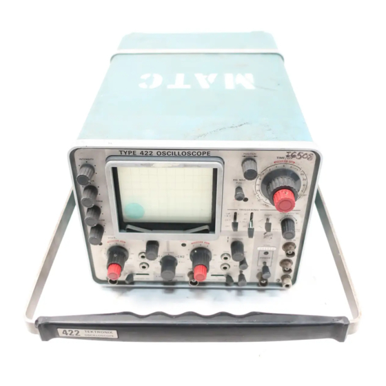
- Page 5 EXT HORIZ). The Tektronix Type 422 Oscilloscope is a solid-state The Type 422 w ith AC-DC Power Supply can be op portable instrument that combines small size and light erated from any one o f three power sources; AC line, exter...
- Page 6 Specification—Type 422 AC-DC Performance Performance Characteristic Characteristic 0.15 division or less compression Maximum Input V o lt Low-Frequency Line or expansion of a center-screen arity two-division signal when posi AC and DC input 300 volts (DC + peak AC). Peak-...
- Page 7 Specification— Type 422 AC-DC Characteristic Performance Characteristic Performance 0.2 division of deflection m ini Permits viewing of leading edge Delay Line mum, DC to five megahertz; in of triggering signal (internal trig creasing to one division at 15 gering only).
- Page 8 Specification—Type 422 AC-DC Performance Characteristic Characteristic Performance Over any two Within 7.5% of equivalent sweep SIGNAL OUTPUTS rate. division portion Gate w ithin center Rectangular. Waveshape eight divisions Polarity N egative-going w ith baseline Sweep Length 10.4 to 12.1 divisions.
- Page 9 Mil-I-6181D cedures, including failure criteria, etc., can be obtain Radiated interference Interference radiated from the ed from Tektronix, Inc. Contact your local Tektronix instrument under test w ithin the Field Office or representative. given limits from 150 kilohertz...
- Page 10 STANDARD ACCESSORIES Width 5 /1 6 inches (26.2 centi Standard accessories supplied with the Type 422 are listed meters). on the last pullout page of the Mechanical Parts List illus Depth (including 9 /1 6 inches (47.2 centi...
-
Page 11: Operating Instructions
Front Cover batteries, or to gain access to the interior of the indicator. The fro n t cover furnished with the Type 422 provides a Loosen the four securing screws located in the rear feet of dust-tight seal around the fron t panel. Use the cover to the power supply (see Fig. - Page 12 Power Mode switch. AC Operation The Type 422 w ith AC-DC Power Supply can be opera Fig. 2-3. Portion of power receptacle used for AC and external DC ted from either a 115-volt or a 230-volt (nominal) AC line...
- Page 13 NOTE tion. The DC power cord is supplied w ithout an input con The bolts removed in step 6 allow the Type 422 with nector. A suitable connector can be added to match the AC-DC Power Supply to meet the EMI specifications power source, or the pigtail leads can be used as supplied.
- Page 14 Operating I nstructions—Type 422 AC-DC Power-supply securing screws Correct position fo r easy removal of the AC-DC Power Supply. Location of securing screws on rear o f power supply. Installing the battery box on the battery pack. Installing the AC-DC Power Supply on the indicator.
- Page 15 (be sure battery pack is charged). The POWER up to reach the specified accuracy. switch on the fron t panel o f the Type 422 controls the power to the circuits in the instrument in the same manner 3. Set the SCALE ILLUM control fu lly counterclock...
- Page 16 Although the battery switch on the fro n t of the indicator is inoperative. The pack is fu lly charged when shipped from Tektronix, Inc., POWER switch can be actuated at the power supply. The recharge the battery pack completely before operating the ON and OFF positions o f the switch are noted on the cir...
- Page 17 CAL position fo r indicated Operating Position deflection). The handle of the Type 422 can be positioned fo r carry ing or as a tilt-stand fo r the instrument. To position the V A R IAB LE Provides variable uncalibrated deflec...
- Page 18 Operating Instructions—Type 422 AC-DC Sweep Triggering Channel 1 Power and External Blanking Fig. 2-7. Front-panel controls and connectors. STEP A T T BAL Screwdriver adjustment to balance the ALG ADD: Signals applied to INPUT input amplifier in the .02, .05 and .1 1 and INPUT 2 connectors are al...
- Page 19 DC to 15 megahertz or greater. Ground Binding post to establish common SLOPE Selects slope o f trigger signal which (not labeled) ground between the Type 422 and the starts the sweep. associated equipment. _ T : Sweep be triggered from positive-going...
- Page 20 For the The follow ing steps demonstrate the use o f the controls OPERATE INT BATT position of and connectors of the Type 422. It is recommended that th e P ow er M ode...
- Page 21 INPUT 1 connector. Position the probe tip so it is in con tact w ith the CALIBRATOR jack. Connect the Type 422 to an AC power source that meets the voltage and frequency requirements of the instru 15. Set the Channel 1 Input Coupling switch to DC.
- Page 22 This completes a description of the basic operating pro 32. Note the CRT display. Then, set the T IM E /D IV cedure fo r the Type 422. Instrument operations not ex switch to 5 ms. Pull the X10 MAG switch. The display...
- Page 23 4 DIVISIONS PULL DIVISIONS INPUT 1 INPUT 2 BLANKING 1 M S I U . .. 6 W I T H X I 3 3 pF 3 3 pF 2 VOLT 1 U PROBE TEKTRONIX, INC.' PORTLAND, OREGON, U.S.A. CALIBRATOR...
- Page 24 General Fig. 2-8 shows the fro n t panel of the Type 422. This 6. Repeat steps 4 and 5 fo r best overall focus. Make chart may be reproduced and used as a test-setup record for final check at normal intensity.
- Page 25 In general, probes offer the most convenient means o f protector and the tinted light filte r mount in the same hol connecting a signal to the input o f the Type 422. Tektronix der. To remove the light filte r or faceplate protector from probes are shielded to prevent pickup of electrostatic inter...
- Page 26 The GND position provides a ground reference at the Loading Effect of Type 422 input of the Type 422 w itho ut the need to externally As nearly as possible, simulate actual operating condi ground the INPUT connectors. The signal applied to the tions in the equipment under test.
- Page 27 The common-mode rejection ratio of the Type works, wave-shaping circuits, etc. The signal from a single 422 is greater than 100:1 at 50 kilohertz. point in the circuit can be connected to the TRIG IN con nector through a signal probe or cable. The sweep is then Deflection Factor.
- Page 28 Operating Instructions—Type 422 AC-DC Waveforms obtained with the TRIGGERING LEVEL control set in the + region. Fig. 2-11. Effect of the TRIGGERING LEVEL control and SLOPE switch on the CRT display. 2 -1 8...
- Page 29 Operating Instructions— Type 422 AC-DC hertz are attenuated. In general, AC coupling can be used the trigger circuit responds at a more positive point on the trigger signal. In the — region, the trigger circuit responds at fo r most applications. However, if the signal contains un...
- Page 30 Horizontal Position Control The dual-range horizontal POSITION control used in the Type 422 provides a combination of coarse and fine adjust ments in a single control. When this control is rotated, fine positioning is provided fo r a range o f about 0.5 division fo r Fig.
- Page 31 (see Fig. 2-14). General The following information describes the procedures and techniques fo r making basic measurements w ith a Type 422 Position to center vertical line Oscilloscope. These applications are not described in detail since each application must be adapted to the requirements o f the individual measurements.
- Page 32 OperatingInstructions—Type 422 AC-DC Instantaneous Voltage Measurements-DC 10. Establish the polarity o f the signal. If the waveform is above the reference line the voltage is positive; below the To measure the DC level at a given point on a waveform, line, negative (with the INVERT switch pushed in fo r Chan...
- Page 33 Operating Instructions— Type 422 AC-DC 2. Set the VO LTS/DIV switch and the VA R IAB LE 1. Connect the reference signal to the INPUT connec VO LTS/DIV control to produce a display an exact number tor. Set the VO LTS/DIV switch fo r fo ur or five divisions of of graticule divisions in amplitude.
- Page 34 Operating Instructions—Type 422 AC-DC Then, w ith a TIM E /D IV switch setting of 50 jus the repeti 8. Measure the horizontal distance between the time tion rate of an unknown signal which completes one cycle measurement points. Be sure the VA R IA B LE T IM E /D IV in seven horizontal divisions can be determined by using the control is set to CAL.
- Page 35 10% and 90% points The calibrated sweep rate and dual-trace features o f the 0.4 and 3.6 divisions Type 422 allow measurement of time difference between 0.5 and 4.5 divisions tw o separate events. To measure time difference use the 0.6 and 5.4 divisions...
- Page 36 5 0 % ship to the sweep, the output o f the signal source can be Amplitude displayed on the CRT as though the Type 422 were trig level T" gered in the normal manner.
- Page 37 45°/division as shown in Fig. The phase difference is 27°. 2-19. Common-Mode Rejection Using the formula: The ALG ADD feature o f the Type 422 can be used to horizontal display signals which contain undesirable components. sweep rate Phase Difference...
- Page 38 Operating I nstructions—Type 422 AC-DC • Line F r a n u o n r v ired - ----- (B) Channel 2 signal. Resultant display. (A ) Channel 1 signal. Fig. 2-21. Using the ALG ADD feature for common-mode rejection: (A) Channel 2 signal contains desired information along with line-frequency component, (B) Channel 2 signal contains line-frequency only, (C) resultant CRT display using common mode rejection.
- Page 39 A basic block controlled by the TIM E /D IV switch. The Sweep Generator diagram of the Type 422 is shown in Fig. 3-1. Only the circuit also produces an unblanking gate signal to unblank basic interconnections between the individual blocks are the CRT so the display can be presented.
- Page 41 CALIBRATOR jack. The effective overall Channel 1 deflection factor o f the Type 422 is controlled by the Channel 1 VO LTS/D IV C IR C U IT OPERATIO N switch. In all positions o f the Channel 1 VO LTS/D IV switch except .01 and .02, the basic deflection factor o f the...
- Page 42 Circuit Description—Type 422 AC-DC Fig. 3-2. Channel 1 Input Amplifier detailed block diagram. ting of the Channel 1 VO LTS/DIV switch. Each attenuator the gate o f Q14A if the signal at the gate exceeds either contains an adjustable series capacitor to provide correct +12.5 volts or —12.5 volts.
- Page 43 Circuit Description— Type 422 AC-DC In the .01 position, R30 provides the emitter resistance tinuously variable deflection factors between the calibrated settings o f the Channel 1 VO LTS/DIV switch. The network fo r Q34 and the gain of the stage is five. In the .02 position, C78-D78-R77-R78-R79 connected to the base o f Q94 pro...
- Page 44 Circuit Description-Type 422 AC-DC SW 110 SW 195 Internal calibrator signal from Channel 2 Calibrator signal to and Regu Vertical lators circuit Switching and Output Amplifier circuit SW 150 Fig. 3-3. Channel 2 Input Amplifier detailed block diagram. Composite CH 1 & 2...
- Page 45 Circuit Description-Type 422 AC-DC from the X9 Gain Stage (nine times amplification) is alge position of the Mode switch, +12 volts is connected to the braically added to the normal signal through the Paraphase collector of Alternate Trace Switching A m p lifie r stage A m plifier stage (one times amplification) to provide an out...
- Page 46 Circuit Description— Type 422 AC-DC Fig. 3-5. Effect of Diode Gate on signal path (simplified Vertical Switching and Output Amplifier diagram). Conditions shown for CH 1 position of Mode switch.
- Page 47 Circuit Description— Type 422 AC-DC CHOPPED. In the CHOPPED position o f the Mode b a s e . T h e d e la y - lin e c o m p e n s a tio n n e tw o rk...
- Page 48 Circuit Description— Type 422 AC-DC External trigger signals applied to the TRIG IN connec the Sweep Generator circuit. These trigger pulses are to r can be used to trigger the sweep in the EXT position o f derived either from the internal trigger signal from the verti...
- Page 49 Circuit Description— Type 422 AC-DC understand the action, assume that the trigger signal at the Trigger TD base o f Q323 is positive-going. This produces a positive The Trigger TD stage shapes the output signal from the going signal at the emitter of Q323 which forward-biases Trigger A m plifier stage to provide a trigger pulse w ith a fast Q324, and its collector goes negative.
- Page 50 Circuit Description—Type 422 AC-DC Fig. 3-7. Current path for (A) positive-slope triggering, (B) negative-slope triggering. control is turned clockwise from midrange to produce a quiescent conditions (no trigger signal) Q345 is biased on display which starts at a more positive level on the selected...
- Page 51 Circuit Description— Type 422 AC-DC When a trigger signal is present, a negative-going pulse is to provide horizontal sweep deflection on the CRT. This connected to the base o f Q345 through T377 and R341 as output signal is generated on command (trigger pulse) from Tunnel Diode D375 switches to its high-voltage state.
- Page 52 Circuit Description—Type 422 AC-DC C440 Trigger pulse from Sweep Sweep to Trigger circuit Horizontal Amplifier Auto gate from Auto circuit Multivibrator stage Fig. 3-8. Sweep Generator detailed block diagram. The sweep gate signal from the collector of Q414 is also...
- Page 53 Circuit Description— Type 422 AC-DC Time/Div Switch. The timing capacitor and resistor are C434-R434 along w ith capacitor C401 delay the voltage selected by the TIM E /D IV switch to provide the various change at the collector o f Q434 to allow a hold o ff period sweep rates listed on the fro n t panel.
- Page 54 Circuit Description— Type 422 AC-DC Horizontal deflection signal to horizontal deflection plates Fig. 3-9. Horizontal Amplifier detailed block diagram. zontal deflection signal is an external signal applied to the For EXT HORIZ operation, an external signal connected HORIZ IN connector. In addition, this circuit contains the...
- Page 55 Circuit Description— Type 422 AC-DC ( X I0 MAG switch pulled out). Variable capacitor C537 C A LIB R A T O R A N D REG ULATO RS provides high-frequency compensation fo r a linear display General (X I operation) at fast sweep rates. When the X I 0 MAG...
- Page 56 Circuit Description—Type 422 AC-DC duces a 200-m illivolt internal signal to the vertical deflec base of Q717 through R716 and R715. Q717 is forward tion system. biased and its emitter rises positive, following the voltage at its base. The voltage at the base of Q714 also rises positive A t the time Q775 turned o ff, C760 was charged nega...
- Page 57 Circuit Description— Type 422 AC-DC Positive High- Voltage Multiplier Drive D810-D816 signal from Power Supply Negative High- Unblanking Voltage gate Multiplier from D821-D823 Sweep Generator circuit Chopped blanking from Vertical High-Voltage Switching Regulator circuit V829 External horizontal unblanking from Sweep...
- Page 58 HORIZ position, a negative level is connected to the emitter of Q864 through R867 (see diagram 6 fo r sche The CRT in the Type 422 uses deflection blanking to matic). Q864 is biased on to unblank the CRT so the exter...
- Page 59 Circuit Description— Type 422 AC-DC SW1001 Fig. 3-12. AC-DC Power Selector detailed block diagram. operated from an AC line. If the internal temperature of connected across the voltage divider composed o f R1022 the instrument exceeds a safe operating level, TK1000 and zener diode D1022.
- Page 60 Power Selection. The power source from which the tion of D1057-R1057 in the OPERATE INT BATT'posi- Type 422 AC-DC Power Supply is operated is selected by tion by SW1030. However since Q1055 is o ff when the the Power Mode switch SW1030. This switch also deter...
- Page 61 Circuit Description— Type 422 AC-DC action occurs. By use of idealized waveforms. Fig. 3-14C current through voltage divider R1043-R1044 produces a shows how this can be done. Notice that the pulse period is more positive voltage at the base of Q1055 to bias it into the same fo r both high source voltage and low source vo lt...
- Page 62 Power in from AC-DC Power Selector circuit J1201...
- Page 63 Circuit Description-Type 422 AC-DC ___ ___________ Pulse Pulse-*-! Duration I duration I Fig. 3-14. Illustration of energy-storage principle: (A) Simplified diagram of energy-storage circuit, (B) graph of charge stored in inductor versus source voltage, (C) idealized waveforms. junction o f D1105 and D l l 15 through R1118. These the collector of Q1120.
- Page 64 Circuit Description— Type 422 AC-DC Fig. 3-15. Idealized DC-DC Regulator circuit waveforms. 3-26...
- Page 65 Circuit Description— Type 422 AC-DC Steering Switch. The Steering Switch stage is controlled and inductors L1 172 and L 1 182 prevent the current surges by two simultaneous input signals. The positive-going pulse at turn-on from affecting the AC-DC Power Selector circuit.
- Page 66 Circuit Description—Type 422 AC-DC ing Switch stage switches to Q1114, the voltage induced to forward biases Q1154 to supply more current to the Pulse Width Control stage. This increase in error current to the the bases o f Q1174 and Q1184 forward biases Q1184 and Pulse Width Control stage reduces the voltage induced in...
- Page 67 Circuit Description— Type 422 AC-DC longer. Since D1155 remains in its high-voltage state longer, D1202-D1223 and C1202-C1203; +55 volt, D1203-D1222 the Steering Switch and Power Control stages conduct fo r a C 1 2 0 4 -C 1 2 0 5 -L 1 2 0 4 ;...
- Page 68 N O TES...
- Page 69 2. Remove the screw located directly below the fuse The severity of the environment to which the Type 422 is holder and remove the battery box and battery pack from subjected determines the frequency o f maintenance.
- Page 70 Exterior. Loose dust accumlated on the outside o f the nickel-cadmium cells used in the battery pack incorporate a Type 422 can be removed with a soft cloth or small paint vent so this internal pressure does not damage the battery.
- Page 71 Circuit Boards. Figs. 4-8 through 4-17 show the circuit The calibration procedure can also be helpful in local boards used in the Type 422. Fig. 4-7 shows the location of izing certain troubles in the instrument. In some cases, each board w ithin the instrument. Each electrical compo...
- Page 72 The white 2. Multimeter ceramic capacitors used in the Type 422 are color coded in Description: VTVM , 10 megohm input impedance and picofarads using a modified EIA code (see Fig. 4-2).
- Page 73 Use the procedure given in the Calibration section to adjust the power supplies. 2. Check Associated Equipment. Before proceeding w ith troubleshooting of the Type 422, check that the TABLE 4-3 equipment used w ith this instrument is operating correctly.
- Page 74 ___________________________________ POWER light Connect to correct power source does not come on Check power source* line cord, fuse, pull POWER switch to ON ------------------------------------------- thermal cutout, POWER switch, power (out)_____________________________ transformer and POWER light buifc POWER light on Outside given Measure power line voltage Connect instrument for cor...
- Page 75 Fig. 4 4 . Troubleshooting chart for Type 422 with AC-DC Power Supply.
- Page 76 DC Power Supply provides about four hours of continuous in the Type 422. Components which are soldered in place operation from a fu lly charged battery pack. The actual are best checked by disconnecting one end. This isolates the operating tim e may vary due to the age of the batteries, measurement from the effects of surrounding circuitry.
- Page 77 Type 422 can be obtained through your local Tektronix Field Office or representative. How 2. When the solder begins to melt, pull the lead out ever, many of the standard electronic components can be gently.
- Page 78 A sample roll of solder containing about 3% silver is mounted in the fro n t cover fo r this instrument. Additional solder of this same type should be available locally, or it can be purchased from Tektronix, Inc. in one-pound rolls; order by Tektronix Part No. 251-0514-00. Chassis...
- Page 79 The Input Am plifier boards and the attenuators can be nal, check the manufacturer's basing diagram fo r correct removed from the Type 422 as a unit, or the circuit boards basing. A ll transistor sockets in this instrument are wired can be removed separately.
- Page 80 If the power transformer becomes defective, re-insert the CRT assembly into the instrument. Be sure the contact your local Tektronix Field Office or representative CRT faceplate seats properly in the subpanel. fo r a warranty replacement (see the Warranty note in the...
- Page 81 Maintenance— Type 422 AC-DC fro n t o f this manual). Be sure to replace only w ith a direct replacement Tektronix transformer. When removing the transformer, tag the leads w ith the corresponding terminal numbers to aid in connecting the new transformer.
- Page 82 DC Powe'' DC Power Control High Voltage Rectifier/Multiplier and High Voltage Channel 1 Channel 2 Regulator Input Amplifier Input Amplifier Trigger/Sweep Generator Calibrator and Regulators Fig. 4-7. Location of circuit boards in the Type 422 and AC-DC Power Supply. 4-14...
- Page 83 Maintenance— Type 422 AC-DC ‘K’ Gy on whl Qrn on wht ‘J’ Yel on wht ‘M ’ Yel on wht (twisted with I) ‘N’ Vio on wht Orn on wht (twisted with M ) *H' Blu on w h t- ‘O ’...
- Page 84 Maintenance-Type 422 AC-DC Red on wht (soldered) twisted Brn on wht (soldered) pair ‘E’ ‘D’ Gy on wht Cl 40 *C' Blu on wht NOTE: R11 2 mounted on rear of board Fig. 4-9. Channel 2 Input Amplifier circuit board.
- Page 85 Maintenance— Type 422 AC-DC ‘R’ Grn on wht ‘Q ’ Yel-yel on gy (coax) ‘S’ Vio on wht ‘P’ Blk on wht T' ® rn'3rn-blk on wht ‘O ’ Blk-red on wht ‘N ’ Brn-red-blk on wht ‘M ’ Blk-grn on wht ‘L’...
- Page 86 Maintenance—Type 422 AC-DC IC434 R434 Q 434 n Q 429 D 4 3 0 * «r<R429 ^ *R433^S) Q441 «C427I R428«B^ R452 'AC' Grn-grn-blk on wht R451 0 4 6 4 ‘AA’ Orn-orn on gy (coax) R447 ‘AB‘ Shield for A A -------------- ‘Y ‘...
- Page 87 Maintenance— Type 422 AC-DC ‘Z’ Gy (coax) 'AC' Red on wht ‘AA’ Shield for Z ► *Y' Shield for X R869 X ’ Grn-grn on gy (coax) W ’ Blk on wht ‘V’ Grn-grn-blk on wht > "Sat ‘U’ Brn-blk-brn on wht -*—...
- Page 88 Maintenance—Type 422 AC-DC 'l\T Grn-grn-blk on w h t 'M ' Vio-grn-blk on w h t 'L ' V io-grn-blk on wht 'K ' G y-blk-blk on tan R 780 J' G y (coax) Q 77 5 I' Shield fo r J...
- Page 89 Maintenance— Type 422 AC-DC ‘N' Grn-grn-blk on wht ‘M ’ Vio-grn-blk on wht ‘L’ Vio-grn-blk on wht ‘K’ Gy-blk-blk on tan . ‘J’ Gy (coax) Shield for J ‘H’ Shield for G ■ ‘G ’ Blu-blu on gy (coax) ^--------‘F* Brn-red-blk on wht ‘E’...
- Page 90 Maintenance—Type 422 AC-DC Fig. 4-14. High Voltage Rectifier/Multiplier circuit board. 4 -2 2...
- Page 91 Maintenance-Type 422 AC-DC Brn on wht (soldered) (soldered) (soldered) Blk on wht (soldered) Yel on wht (soldered) Brn-yel on wht (soldered) Brn on wht (soldered) Red on wht (soldered) Red on wht (soldered) Blu on wht (soldered) Orn on wht...
- Page 92 Maintenance—Type 422 AC-DC Fig. 4-16. DC Power Converter circuit board 4-24...
- Page 93 Maintenance— Type 422 AC-DC Fig. 4-17. DC Power Control circuit board. 4 -25...
- Page 94 NO TES...
- Page 95 To assure instrument accuracy, check the calibration of the instrument between major recalibrations. To check or the Type 422 every 1000 hours of operation, or every six adjust only part o f the instrument, set the controls as given months if used infrequently. Before complete calibration,...
- Page 96 Supply power receptacle. Tektronix Part No. 161-0015-01. w ith range o f at least 137 or 274 volts, RMS.) For example. 15. 50-ohm resistor. 10 w att, 5%. Tektronix Part No. General Radio W10MT3A Metered Variac Autotransformer (use General Radio W20HMT3A for 230-volt nominal line).
- Page 97 Performance Check/Calibration— Type 422 AC-DC Ripple SHORT-FORM PROCEDURE Type 422, Serial No. _______________ PERFORMANCE: Supply REQUIREMENT: (maximum) Calibration D a te ------------------------------- - 1 2 volt 8 millivolts millivolts Calibrated B y ------------------------------------ millivolts +12 volt 8 millivolts millivolt +10.5 volt 1 millivolt 1.
- Page 98 Performance Check/Calibration— Type 422 AC-DC 19. Check Channel 2 X I 0 Gain Page 5-19 13. Check/Adjust Channel 1 Step Attenu- Page 5-16 ator and Variable Balance (R21, R35) REQUIREMENT: Four divisions ±0.16 division vertical deflection at .05 VO LTS/DIV, X10 GAIN AC pulled out REQUIREMENT: Step attenuator balance, less than 0.1...
- Page 99 Performance Check/Calibration—Type 422 AC-DC 26. Check/Adjust Channel 2 Volts/Division Page 5-21 33. Adjust Channel 1 Only Triggering DC Page 5-25 Level (R57) Switch Compensation (C103B, C103C, C104B, C104C, C105B, C105C, C106B, C 106C,Cl 12) REQUIREMENT: Zero volts w ithin 50 m illivolts output from the Channel 1 Trigger Pickoff stage.
- Page 100 Performance Check/Calibration— Type 422 AC-DC C h e c k /A d ju s t Normal-Magnified Page 5-31 38. Check Low-Frequency Reject Opera- Page 5-28 Registration (R535) tion REQUIREMENT: Stable display w ith 0.2-division REQUIREMENT: Less than 0.2-division shift o f marker display at 50 kilohertz;...
- Page 101 ------ millivolts; CALIBRATE 4 DIVISIONS C hannel 1 , w ith in ------- division; Channel 2. w ithin 1. Connect the Type 422 to a power source which meets ------ division. the voltage and frequency requirements of this instrument.
- Page 102 2. Set the controls as given under Preliminary Control Preliminary C ontrol Settings Settings. A llow at least 20 minutes warmup before Set the Type 422 controls as follows: proceeding. CRT Controls INTENSITY Midrange 3. Begin the performance check w ith step 6.
- Page 103 Performance Check/Calibration— Type 422 AC-DC Variable DC Time-mark generator power supply probe DC power Three-inch cord screwdriver Fig. 5-1. Test equipment required for steps 1 through 15. d. CHECK— Meter reading; —12 volts ±0.12 volt. 1. A d ju s t-1 2 -V o lt Supply PERFORMANCE CHECK ONLY e.
- Page 104 Performance Check/Calibration—Type 422 AC-DC GEOM i — 1 1 o-V oiti + 12-Volt — Test Point ' + 95-Volt Test Point Test Point — 12-Volt Test Point R1130 12-Volts R1125 Oscillator frequency Fig. 5-2. (A) Location of -12-volt and + 12-volt power supply test points (left side of indicator), (B) location of DC power supply adjustments (DC Power Control board).
- Page 105 Performance Check/Calibration— Type 422 AC-DC TABLE 5-1 Power Supply O utput Voltage and Ripple Power Supply Output Voltage Range Maximum Ripple2 (peak to peak) High Frequency AC Line Frequency — 12 volt —11.9 to —12,1 volts 20 m illivolts 8 m illivolts + 12 volt + 11.7 to + 12.3 volts...
- Page 106 Performance Check/Calibration—Type 422 AC-DC Fig. 5-5. Typical test oscilloscope display of power-supply ripple (sweep rate 20 microseconds/division). Adjust Low-Voltage Indicator a. Set the Power Mode switch (rear panel) to OPERATE I NT BATT. b. Connect the variable DC power supply positive output to the bottom battery-interconnection banana plug (see Fig.
- Page 107 Performance Check/Calibration— Type 422 AC-DC f. Set the autotransformer output voltage to 126.5 (or f. Set the autotransformer output voltage to 95 or 190) 253) volts. volts. g. CHECK— Output voltage o f each supply w ith the precision DC voltmeter fo r the tolerances given in Table g.
- Page 108 Performance Check/Calibration—Type 422 AC-DC Fig. 5-8. Location of Unblanking Center adjustment (Horizontal Amplifier board). Fig. 5-7. Location of high-voltage test point (rear panel, socket cover removed). d. Set the Channel 1 VO LTS/DIV switch so the large Adjust the FOCUS and ASTIGMATISM controls for a markers extend beyond the top and bottom o f the graticule well defined display.
- Page 109 Performance Check/Calibration— Type 422 AC-DC 12. Check/Adjust CRT Geometry R856 Y-Axis Align a. Set horizontal POSITION V A R IA B LE TIM E /D IV controls so a large marker coincides w ith each graticule line. b. CHECK— CRT display fo r 0.1 division or less bowing of the markers at the left and right edges of the graticule.
- Page 110 Performance Check/Calibration—Type 422 AC-DC i. CHECK—Deviation from straight line should not exceed ±0.1 division. j. Return the VA R IAB LE T IM E /D IV control to CAL. 13. Check/Adjust Channel 1 Step Attenuator and Variable Balance a. Set both Input Coupling switches to GND.
- Page 111 Performance Check/Calibration— Type 422 AC-DC h. Return the Channel 1 VA R IAB LE VO LTS/DIV a. Change the following control settings: control to CAL. CH 1 and 2 V O LTS/D IV Vertical Mode A L T i. Repeat steps b through h fo r minimum trace shift for...
- Page 112 Performance Check/Calibration— Type 422 AC-DC High-frequency Low-frequency Square-wave constant-amplitude constant-amplitude Standard generator sine-wave generator sine-wave amplitude generator calibrator s®— — e-‘9* 42-inch BNC to dual Dual-input BNC cable GR to BNC Tuning binding post coupler adapter tool adapter Three-inch screwdriver...
- Page 113 Performance Check/Calibration— Type 422 AC-DC g. Change the following control settings: c. Change the following control settings: CH 2 Input Coupling CH 1 Input Coupling Vertical Mode ALG ADD CH 2 Input Coupling INVERT Pulled out Vertical Mode CH 2 h.
- Page 114 Performance Check/Calibration—Type 422 AC-DC k. Position the top o f the display to the top horizontal line of the graticule. . CHECK— Compression or expansion not to exceed 0.15 division (see Fig. 5-16). m. Position the bottom o f the display to the bottom horizontal line of the graticule.
- Page 115 Performance Check/Calibration— Type 422 AC-DC TABLE 5-3 c. CHECK— Set the Channel 1 Input Coupling switch to DC; trace shift should be negligible. Channel 1 VO LTS/D IV Switch Compensation d. Set the vertical Mode switch to CH 2. Channel 1...
- Page 116 Performance Check/Calibration—Type 422 AC-DC —L ncor rect ncor rect orre< — spike ar d tc )p not f at) rollo ff a nd t ot f lat) [opt mum sqi corn er cnd lat top) l _ 4 (A ) Fig.
- Page 117 Performance Check/Calibration— Type 422 AC-DC h. Set the square-wave generator for a five-division dis TABLE 5-4 play at 100 kilohertz in the fast-rise mode. Channel 2 VOLTS/DIV Switch Compensation i. CHECK—CRT display fo r optimum square-wave Adjusted fo r optimum Channel 2 response similar to Channel 1 response.
- Page 118 Performance Check/Calibration—Type 422 AC-DC b. Connect the high-frequency constant-amplitude sine- d. Change the following control settings: wave generator (Type 191) to the INPUT 2 connector Vertical Mode A LG ADD through the GR to BNC adapter, 18-inch 50-ohm BNC INVERT Pulled out cable and the 50-ohm BNC termination.
- Page 119 Performance Check/Calibration— Type 422 AC-DC 32. Check Channel Isolation Ratio a. Test equipment required fo r steps 33 through 53 is shown in Fig. 5-19. a. Change the fo llo w in g c o n tro l settings: CH 1 VOLTS/DIV b.
- Page 120 Performance Check/Calibration— Type 422 AC-DC Test High-frequency oscilloscope constant-amplitude Low-frequency Square-wave sine-wave Time-mark constant-amplitude generator generator generator sine-wave generator « BNC to Low-capacitance dual binding screwdriver post probe GR to BNC attenuators Three-inch screwdriver adapter 50-ohm 1 8-inch 50-ohm BNC...
- Page 121 Performance Check/Calibration— Type 422 AC-DC 36. Check High-Frequency Triggering Operation a. Change the following control settings: CH 1 and 2 VO LTS/DIV TRIGGERING Source CH 1 & 2 TRIGGERING Coupling TIM E /D IV .5 jus b. Connect the high-frequency constant-amplitude sine-...
- Page 122 Performance Check/Calibration— Type 422 AC-DC n. W ithout changing the output amplitude, set the e. CHECK— Stable CRT display can be obtained with constant-amplitude generator output frequency to five TRIGGERING Coupling switch set to AC and DC (LEVEL megahertz. control may be adjusted as necessary to obtain a stable display).
- Page 123 Performance Check/Calibration— Type 422 AC-DC c. CHECK—Rotate the LEVEL control throughout its range and check that the display can be triggered (stable display) at any point along the negative slope o f the wave form (indicates LEVEL control range o f at least + and — 10 volts).
- Page 124 Performance Check/Calibration-Type 422 AC-DC Fig. 5-24. Typical CRT display when checking sweep length. 43. Check Sweep Length a. Position the tenth marker to the center vertical line w ith the horizontal POSITION control (see Fig 5-24). b. CHECK— Sweep length between 10.4 and 12.1 divi...
- Page 125 Performance Check/Calibration— Type 422 AC-DC i. CHECK—Marker w ithin 0.15 division (within 7.5%) of the fourth vertical line. j. Position the marker nearest the third vertical line exactly to that line. k. CHECK—Marker w ithin 0.15 division (within 7.5%) o f the fifth vertical line.
- Page 126 Performance Check/Calibration—Type 422 AC-DC e. CHECK—CRT display fo r four-division maximum spacing between markers (indicates adequate range fo r con tinuously variable sweep rates between the calibrated steps). f. Return the VA R IA B LE TIM E /D IV control to CAL.
- Page 127 Performance Check/Calibration— Type 422 AC-DC h. ADJUST— C527 (see Fig. 5-27) fo r one marker each 52. Check Gate Output Signal division (use low-capacitance screwdriver). a. Change the following control settings: TRIGGERING Source CH 1 & 2 i. Repeat parts c through h o f this step until optimum tim ing is obtained.
- Page 128 Performance Check/Calibration— Type 422 AC-DC Amplituc le - five divisions or greatc r Duration - 5.2 to 6.25 divisions Fig. 5-28. Typical test oscilloscope display when checking GATE Fig. 5-29. Typical CRT display when checking chopped repetition OUT signal (vertical deflection 0.1 volt/division; sweep rate two rate and blanking.
- Page 129 Performance Check/Calibration-Type 422 AC-DC Precision voltmeter Standard Low-frequency amplitude constant-amplitude calibrator sine-wave generator BNC T Dual 1 8-inch Three-inch 50-ohm connector 42-inch binding post BNC cable screwdriver probe 50-ohm adapter termination BNC cable Fig. 5-30. Test equipment required for steps 54 through 59.
- Page 130 Performance Check/Calibration— Type 422 AC-DC 55. Check External Horizontal Bandwidth a. Turn the HORIZ ATTEN control fu lly clockwise. b. Connect the low-frequency constant-amplitude sine- wave generator to the HORIZ IN connector through the BNC to dual binding post adapter, 42-inch 50-ohm BNC cable and 50-ohm BNC termination.
- Page 131 Set the vertical Mode switch to CH 2. This completes the checkout/calibration procedure fo r the Type 422 w ith AC-DC Power Supply. Replace the cabi o. CHECK—CRT display four divisions ±0.06 division in net and re-attach the power supply to the indicator. If the amplitude (internal calibrator accuracy w ithin 1.5%, C A LI...
- Page 132 NO TES...
- Page 133 PARTS LIST A B B R E V IA TIO N S binding head brass internal length or long binding head steel met. metal cap. capacitor mounting hardware mtg hdw ceramic outside diameter composition comp oval head brass conn connector oval head steel cathode-ray tube part of...
- Page 134 If a part you have ordered has been replaced with a new or improved part, your local Tektronix, Inc. Field Office or representative will contact you concerning any change in part number.
- Page 135 Type 422 AC-DC SECTION 6 ELECTRICAL PARTS LIST Values are fixed unless marked Variable. IN D IC A T O R Tektronix Serial/Model No. Ckt. No.____________Part No. Eff_____________ Disc_______________________ Description Bulbs B725 150-0059-00 Incandescent #386 Incandescent B726 150-0059-00 150-0035-00 Neon, AID...
- Page 136 Electrical Parts List— Type 422 AC-DC IN D IC A T O R (cont) Serial/Model Tektronix Description Ckt. No. Part No. Disc Capacitors (cont) 283-0068-00 0.01 500 V 0.01 283-0068-00 500 V Elect. 290-0246-00 Elect. 290-0134-00 j u l a 01...
- Page 137 Electrical Parts List— Type 422 AC-DC IN D IC A T O R (cont) Tektronix Serial/Model No. Disc Description Ckt. No. Part No. Capacitors (confj C242 8 pF 500 V ± 0 .5 pF 281-0503-00 C252 281-0503-00 8 pF 500 V ±...
- Page 138 Electrical Parts List— Type 422 AC-DC IN D IC A T O R (cont) Tektronix Serial/Model No. Ckt. No. Part No. Disc Description Capacitors (cont) C511 281 -0076-00 1.2-3.5 pF/ Var C514 283-0068-00 0.01 /x F 500 V C527 Tub.
- Page 139 Electrical Parts List— Type 422 AC-DC IN D IC A TO R (cont) Tektronix S erial/M odel Ckt. No. Part No. Disc Description Semiconductor Device, Diodes *152-0323-00 Silicon Tek Spec Silicon Tek Spec *152-0323-00 152-0141-02 Silicon 1N4152 152-0166-00 Zener 1N753A 400 mW, 6.2 V, 5% Zener 1N753A 400 mW, 6.2 V, 5%...
- Page 140 Electrical Parts List— Type 422 AC-DC IN D IC A TO R (cont) Tektronix Serial/Model No. Ckt. No. Part No. Description Disc Semiconductor Device, Diodes (cont) D408 152-0141-02 1N4152 Silicon D430 152-0333-00 High speed and conductance Silicon D438 *152-0185-00 Replaceable by 1N4152...
- Page 141 Electrical Parts List— Type 422 AC-DC INDICATOR (cont) Tektronix Serial/Model No. Ckt. No.____________Part No. Eff_____________ Disc_______________________ Description Inductors Core, Ferrite 276-0541-00 LI 5 Toroid, 5 turns single *120-0407-00 LI 01 276-0541-00 Core, Ferrite LI 25 *120-0407-00 Toroid, 5 turns single...
- Page 142 Electrical Parts List— Type 422 AC-DC INDICATOR (con!) Tektronix S erial/M odel No. Ckt. No. Part No. Disc Description Transistors (cont) Q265 151-0220-00 Silicon 2N4122 Q275 151-0220-00 Silicon 2N4122 Q283 151-0220-00 Silicon 2N4122 Q294 151-0223-00 Silicon 2N4275 Q323 151-0220-00 Silicon...
- Page 143 Electrical Parts List— Type 422 AC-DC IN D IC A TO R (cont) Tektronix Serial/Model No. Ckt. No.___________ Part No. Eff_____________ Disc_______________________ Description Resistors (c o n t) 111 ka 321-1389-01 Prec 322-0624-01 990 ka Prec ' A W y .w 321-1289-01 io .i...
- Page 144 Electrical Parts List— Type 422 AC-DC IN D IC A T O R (conf) Tektronix Serial/Model Ckt. No. Part No. Disc Description Resistors [conf] 321-0085-00 75 O y8 w Prec 315-0271-00 270 a ’A w 47 0 ’A W 315-0470-00...
- Page 145 Electrical Parts List— Type 422 AC-DC INDICATOR (con!) Tektronix Serial/Model No. Ckt. No.____________Part No. Eff_____________ Disc_______________________ Description Resistors (c o n f) 'A W R144 322-0170-00 76 a Prec 150 a y4 w R145 315-0151-00 R 151 321-0136-00 255 a Prec 8.66 ka...
- Page 146 Electrical Parts List— Type 422 AC-DC IN D IC A TO R (cont) Serial/Model Tektronix Ckt. Part No. Disc Description Resistors (c o n t) R231 321-0159-00 442 O y « w Prec 464 n R234 321-0161-00 Prec R235 315-0102-00...
- Page 147 Electrical Parts List— Type 422 AC-DC IN D IC A T O R (cont) Tektronix Serial/Model No. Ckt. No. Part No. Disc Description Resistors (c o n t) ’A R 341 315-0201-00 R342 315-0301-00 V4 w R343 315-0103-00 10kO ’A W...
- Page 148 Electrical Parts List— Type 422 AC-DC IN D IC A TO R (cent) Tektronix S erial/M odel No. Disc Description Ckt. No. Part No. Resistors (cont) ’A 10 kO R438 315-0103-00 311-0468-00 100 kO, Var R440A6 47 ko ’A W...
- Page 149 Electrical Parts List— Type 422 AC-DC IN D IC A T O R (cont) Tektronix Serial/Model No. Ckt. No. Part No. Disc Description Resistors (cont] 311-0510-00 10 ka, Var R512 10ka R513 315-0103-00 315-0100-00 10 Q R514 315-0473-00 47 kQ...
- Page 150 Electrical Parts List— Type 422 AC-DC IN D IC A T O R (cont) Tektronix Serial/M odel No. Ckt. No. Part No. Disc Description Resistors (contj R736 315-0474-00 X28000 470 ka y4 w R737 315-0102-00 'A W X28000 1 ka...
- Page 151 Electrical Parts List— Type 422 AC-DC IN D IC A TO R (cont) Tektronix Serial/Model No. Description Disc Ckt. No. Part No. Switches Wired or Unwired CH 1 AC GND DC Lever 260-0665-00 20000 30639 CH 1 AC GND DC...
- Page 152 Electrical Parts List— Type 422 AC-DC POW ER SUPPLY 0073 Tektronix Serial/Model No. Ckt. No. Part No. Eff_____________ Disc_______________________ Description_____________________ Battery BT1014 016-0066-02 Battery Pack (contains 20X size “D" Nickel-cadmium cells) Values are fixed unless marked Variable. Capacitors Tolerance ± 2 0 % unless otherwise indicated.
- Page 153 Electrical Parts List— Type 422 AC-DC POW ER SUPPLY (con!) Tektronix Serial/Model No. Ckt. No. Part No. Disc Description Capacitors (cont) Cl 226 283-0013-00 0.01 1000 V C1231 283-0008-00 500 V j l l Cl 232 290-0187-00 Elect. j u l...
- Page 154 Electrical Parts List— Type 422 AC-DC POWER SUPPLY (con!) Tektronix Serial/Model No. Part No. Disc Description Ckf. No. Semiconductor Device, Diodes (c o n t) Tek Spec Silicon *152-0061-00 D ll 87 Silicon Tek Spec D ll 89 *152-0061-00 Silicon...
- Page 155 Electrical Parts List— Type 422 AC-DC POWER SUPPLY (con!) Tektronix Serial/M odel Ckt. No. Part No. Disc Description Inductors (cont) LI 213 276-0525-00 Core, Ferrite LI 217 *108-0336-00 100 juH LI 219 276-0525-00 Core, Ferrite LI 246 *120-0415-00 Toroid, 8 turns single...
- Page 156 Electrical Parts List— Type 422 AC-DC POWER SUPPLY (con!) Tektronix Serial/Model No. Description Ckt. No. Part No. Disc Resistors (cont) ’A W Rll 06 315-0220-00 R1113 315-0471-00 ’A W 470 a ’A W Rill 6 315-0220-00 315-0182-00 ’A W R1117 ’A W...
- Page 157 Electrical Parts List— Type 422 AC-DC POWER SUPPLY (contJ Tektronix Serial/Model No. Ckt. No.____________ Part No. Eff_____________ Disc_______________________ Description Transformers n ooo *120-0397-00 Toroid, 10 turns bifilar T1 001 *120-0392-00 Power T1010 *120-0397-00 Toroid, 10 turns bifilar T il 20...
- Page 159 Mounting hardware must be purchased separately, unless otherwise specified. PARTS ORDERING IN F O R M A T IO N Replacement parts are available from or through your local Tektronix, Inc. Field Office or representative. Changes to Tektronix instruments are sometimes made to accommodate improved components as they become available, and to give you the benefit of the latest circuit improvements developed in our engineering department.
- Page 160 M echanical Parts List — Type AC-DC INDEX M E C H A N IC A L PARTS LIST ILLUSTRATIONS (Located behind diagram s) FIG. 1 FRONT FIG. 2 CHASSIS FIG. 3 AC-DC POWER SUPPLY FIG. 4 ACCESSORIES...
- Page 161 Type 422 AC-DC SECTION 7 M ECHANICAL PARTS LIST FIG. Fig. & index Tektronix Serial/Model Description Part No. Disc 5________________________ ________________ 262-0845-00 SWITCH, wired— CH 1 VOLTS/DIV switch includes: 260-0661-01 SWITCH, unwired 441-0789-00 CHASSIS, attenuator mounting hardware: (not included w/chassis)
- Page 162 Mechanical Parts List— Type 422 AC-DC FIG. 1 FRONT ( con t) Fig. & Index Tektronix Serial/Model No. Description Part No. Disc 1 2 3 4 5 ASSEMBLY, circuit board— CHANNEL 1 PREAMP 1-16 670-0404-02 20000 27999 670-0404-02 28000 ASSEMBLY, circuit board— CHANNEL 1 PREAMP...
- Page 163 Mechanical Parts List— Type 422 AC-DC FIG. 1 FRONT (c on t) Fig. & Index Tektronix Serial/Model No. Descriotion 1 2 3 4 5 Part No. Eff____________ Disc __________________ ASSEMBLY, front cover 1-33 200-0604-02 assembly includes: CUSHION, cover bottom 348-0077-00...
- Page 164 Mechanical Parts List— Type 422 AC-DC PIG. 1 FRONT (c on t) Fig. & Index Tektronix Serial/Model No. Description Disc Part No. CAPACITOR 1-56 mounting hardware for each: (not included w/capacitor) FASTENER, plastic 214-0456-00 SHIELD, attenuator 337-0716-00 ROD, shaft, gain...
- Page 165 Mechanical P arti List— 4 22 AC-DC FIG. 1 FRONT ( con t) Fig. & Index Tektronix Serial/Model No. Description Part No. Disc BRACKET, switch, rear 407-0101-00 1-76 mounting hardware: (not included w/bracket) LOCKWASHER, #6, split 210-0055-00 NUT, hex., 5-40 x V4 inch...
- Page 166 Mechanical Parts List— Type 422 AC-DC FIG. 1 FRONT (cont) Fig. & Index Tektronix Serial/Model No. Descriotion 1 2 3 4 5 Part No.________ Eff____________ Disc __________________ P 1-94 210-0255-00 LUG, solder, % inch OD - 9 5 ........... RESISTOR, variable ...................
- Page 167 Mechanical Parts List— Type 422 AC-DC FIG. 1 FRONT (c o n t) Fig. & Index Tektronix Serial/Model No. Description Part No. Disc 5__________________________________________ ASSEMBLY, cabinet 1-108 437-0076-00 assembly includes: FOOT, bottom -109 348-0069-00 mounting hardware for each: (not included w/foot)
- Page 168 Mechanical Parts List— Type 422 AC-DC FIG. 1 FRONT fconf) Fig. a Index Tektronix Serial/Model No. Description Part No. Disc 1 2 3 4 5 CONNECTOR, coaxial, 1 contact, BNC w/hardware 1-128 131-0352-00 RESISTOR, variable - 1 2 9 ....
- Page 169 Mechanical Parts List— Type 422 AC-DC FIG. 2 CHASSIS Fig. & Index Tektronix Serial/Model No. Description Part No. Disc 179-0941-02 20000 303999 CABLE HARNESS, vertical 179-0941-03 304000 CABLE HARNESS, vertical cable harness includes: 131-0371 -00 CONNECTOR, single contact, female 670-0407-02...
- Page 170 Mechanical Parts List— Type 422 AC-DC FIG. 2 CHASSIS fconf) Fig. & Tektronix Serial/Model No. Index Description Disc Part No. 1 2 3 4 2-21 441-0601-03 20000 24999 CHASSIS, main frame CHASSIS, main frame 441-0601-05 25000 mounting hardware: (not included w/chassis) .........
- Page 171 Mechanical Parti List— Type 422 AC-DC FIG. 2 CHASSIS (c o n t) Fig. & Index Tektronix Serial/Model No. Description Part No. Disc 1 2 3 2-37 214-0524-00 ACTUATOR, X I0 Gain AC switch ASSEMBLY, circuit board—CALIBRATOR 420-02 20000 27999...
- Page 172 Mechanical Parts List— Type 422 AC-DC PIG. 2 CHASSIS (c o n t) Fig. & Index Tektronix Serial/Model No. Description Part No. __________ Disc______ y ______________________ 1 2 3 4 5 SOCKET, transistor, 3 pin 2-53 136-0183-00 SOCKET, transistor, 3 pin...
- Page 173 Mechanical Parts List— Type 422 AC-DC FIG. 2 CHASSIS (c o n t) Fig. & Tektronix Serial/Model No. Index Description Part No. Disc 5___________________________________________ 2-70 358-0244-00 BUSHING, flange mounting hardware for each: (not included w/bushing) 211-0014-00 SCREW, 4-40 x y2 inch, PHS 210-0851-00 WASHER, flat, 0.119 !D x % inch OD...
- Page 174 Mechanical Parts List— Type 422 AC-DC FIG. 2 CHASSIS (c o n t) Fig. & Index Tektronix Serial/Model No. Description Disc Part No. ASSEMBLY, high-voltage power 621-0423-00 assembly includes: BOX, high-voltage 202-0135-00 ASSEMBLY, circuit board— HIGH-VOLTAGE RECTIFIER 670-0410-00 assembly includes:...
- Page 175 M echanical Parts List— Type 422 AC-DC FIG. 3 AC-DC POWER SUPPLY Fig. & Index Tektronix Serial/Model No. Description Part No. Disc 016-0073-00 AC-DC POWER SUPPLY AC-DC power supply includes: 670-0082-00 ASSEMBLY, circuit board, wired— DC POWER CONVERTER assembly includes:...
- Page 176 Mechanical Parts List— Type 422 AC-DC FIG. 3 AC-DC POWER SUPPLY (cont) Fig. & Index Tektronix Serial/Model No. Descriotion Part No. Disc______ y ______________________ 1 2 3 4 5 TRANSFORMER 5-14 mounting hardware: (not included w/transformer) SCREW, 6-32 x % inch, THS 211-0537-00 WASHER, flat, 0.150 ID x...
- Page 177 Mechanical Parts List— Type 422 AC-DC FIG, 3 AC-DC POWER SUPPLY fconfj Fig. & Index Tektronix Serial/M odel No. Description Part No. Disc 5___ _____ _____ _______ TRANSFORMER 3-26 mounting hardware: (not included w/transformer) SCREW, 6-32 x 1 % inches, PHS 211-0530-00 WASHER, flat, 0.150 ID x 5 / 1 6 inch OD...
- Page 178 Mechanical Parts List— Type 422 AC-DC FIG. 3 AC-DC POWER SUPPLY (cont) Fig. & Tektronix Serial/Model No. Index Description Disc Part No. BOX, battery, power supply 202-0138-00 3-41 box includes: FOOT, bottom 348-0069-00 mounting hardware for each: (not included w/foot)
- Page 179 SECTION 8 DIAGRAMS The following symbols are used on the diagrams: Screwdriver adjustment Front-, side- or rear-panel control or connector ------w Clockwise control rotation in direction of arrow Refer to indicated diagram < > Connection circuit board made with connector at indicated pin Connection soldered to circuit board Blue line encloses components located on circuit board...
- Page 180 .fo e B U D C K - D \A G .£ -A N \ T Y P E . 4 Z 2 A C - D C (s>/N e o ,o o o - u p )
- Page 181 V A R IAB LE Input impedance 10 Megohms, 7.5 picofarads Input Coupling (with 10X probe) POSITION Midrange Probe ground Type 422 chassis ground Mode CH 1 Trigger Source External from Type 422 INVERT Pushed in GATE OUT connector to in...
- Page 182 0.5V/D1V INPUT C O U P L IN G C A LIB R A TE S W I 1 IN P U T )~| 4 D IV IS IO N S -OM> <>€-0- A/V-0-K) C W I I ■ i f ^ o o-<- TRIGGER SIGNAL...
- Page 183 - H 0 . 5 V “0 > § < > N P U T A M P L I F I E R <§> 0 271 C H A N N E L T Y P E 4 - 2 2 A C - D C S /N 2 0 ,0 0 0 - UP...
- Page 184 -4- Z 4- < 4 - )..... * C3C _ - C3D C4-B R4C < C4-C C 3 B - £ R3C< 750K: 7" .7-11 1.7-n 1 . 3 - 5 .4 - " 1.7-II " " <&.© s o o k •...
- Page 185 4- 2 J --------------------------------------- CIOAB _^R I04C < C104C ^ C I 0 3 G ^ R I 0 3 C < C I 0 3 D C I O B B - 1.7- M 1 .3 -6 .4 7 1.7-1 I 7 ' “...
- Page 186 T Y P t. ^-2.a AC-DG V E R T I C A L S W I T C H I N G O U T P U T A M P L I F I E R <£> (s>/N e q o o o -up)
- Page 187 S W E E P T R I G G E R <3> T Y P E 4 1 2 A C - D C 1 2 6 8 2 0 , 0 0 0 - U P ) ( s / M...
- Page 188 O.SV/DtV S A W T O O T H O U T •2-V/osV O.S>V/OtV W/OIV TTUC*C*fe.R SIC»NAL-> FROM D 4 ° \ ^ 2v««,/DW AUTO C\ATt FROM RAO\ < $ > 4 OUTPUT AMPLIFIER <S> SWEEP TRIGGER <^> TIMING SWITCH <&>...
- Page 189 S W E E P T R IG G E R S ill PARTS LIST FO i EARLIER VALUES SERIAL NUMBER S W E E P GENERATOR O f PACTS MARKED RANGES W IT H BLUE OUTLINE. H O R IZ O N T A L A M P L IF IE R 8<s?e T I M I N G S W I T C H <^>...
- Page 190 io .s v __ _ MAG R E G IS T E R | N O R IZ A T T E N | / G A U G ED W IT H T R IG G E R IN G L E V E L <$>...
- Page 191 H O R I Z O N T A L A M P L I F ( s / N z o , o o o - u p )
- Page 193 C A L. R E G 0670 C A L I B R A T O R R E G U L A T O R S <§> T Y P t 4 2 2 AC - D C ( S . / N -Z& fO O O - U P )
- Page 194 0 6 7 0 ® C A L I B R A T O R £ R E G U L A T O R S <J> T Y P f e ^ 2 A C - D C 'll, (.S./N 20,000 - <...
- Page 195 CRT CIRCUIT <10 <$> < u- > C V J < 0 < z > U js...
- Page 196 J > T Y P t 4 Z 2 A C - D C A C - D C P O W t R ‘E ^ .L ^ C T O R . <11) ( s / N e o ; o o o - u p )
- Page 197 POWER IN PROW AC-DC. POWER SELECTOR < C x * - A T \C U \_ E . L \ C V \ T S “ < T B O \ < < § > + \ 2 . P O N A /E .^ . NEON <...
- Page 198 FIG 1 FRONT TYPE 422 AC-DC...
- Page 199 CHASSIS...
- Page 200 TYPE 422 AC-DC...
- Page 201 FIG 3 AC-DC POWER SUPPLY TYPE 422 AC-DC...
- Page 202 103-0013-001 161-0015-011 CORD, power, 18 ga. 8 ft. 3 wire, AC 161-0016-011 CORD, power, 18 ga. 8 ft. 3 wire, DC MANUAL, instruction (not shown) 070-0895-00 1 All furnished with power supply when purchased separately ® i TYPE 422 AC-DC...
- Page 203 M A N U A L C H A N G E IN F O R M A T IO N At Tektronix, we continually strive to keep up with latest electronic developments by adding circuit and component improvements to our instruments as soon as they are devel...
- Page 204 TYPE 422 AC-DC TENT SN 25200 STANDARD ACCESSORIES CORRECTION FIG. 4 ACCESSORIES CHANGE: Fig. & Index No. 4-4 to read: 378=0648-00 1 FILTER, mesh (installed) M15,369/470...
- Page 206 Battery Pack— 422 AC-DC Copyright © 1966, Tektronix, Inc., Beaverton, Oregon. Printed in the United States of America. rights reserved. Contents of this publication may not be reproduced in any form without permis sion of the copyright owner.
- Page 207 Battery Pack— 422 AC-DC BATTERY PACK IN S T A L L A T IO N IN S T R U C T IO N S 4 2 2 BATTERY PACK 1. R em oving th e P o w er Supply...
- Page 208 Battery Pack— 422 AC-DC 2. Attaching the Battery Pack Remove and discard the four screws from the Battery Pack securing screw holes. Battery Pack Loosen and remove from the Battery Pack the four long screws which go through it near its corners.
- Page 209 Battery Pack— 4 2 2 AC-DC Place the battery box over the Battery Pack so that the cutout in the Battery Pack is directly under the knob, fuse and input connector holes in the battery box. Start each of the four long screws, removed from the Battery Pack in step 2b into the four holes indicated, then tighten the four screws securely.
- Page 210 This completes the Battery Pack installation procedure. For more information on the Battery Pack refer to the instruc tion manual for the Type 422 AC-DC Power Supply. ®...
- Page 211 The battery pack can be charged over an ambient tem perature range of —15°C to + 4 0 °C. However, the maxi The Type 422 with AC-DC Power Supply provides about mum operating time and useful battery life is provided four hours of continuous operation from a fully charged bat...
- Page 212 If the battery pack is found to be defective, the entire bat instrument must be stored at either high ambient temperature tery pack should be returned to Tektronix, Inc. for mainte or high humidity for an extended period of time, it is recom...
- Page 213 BATTERY PACK (Part No. 016-0066-02) F ig. & I n d e x T e k tro n ix S e r ia l/M o d e l N o . D escrip tio n P a rt N o ._____ Eff________ P ise ________ y 1 2 3 4 5 H o .
Need help?
Do you have a question about the 422 and is the answer not in the manual?
Questions and answers