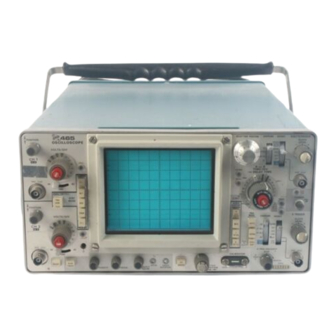
Tektronix 465 Instruction Manual
Wth options, sn b250000 & up
Hide thumbs
Also See for 465:
- Instruction manual (236 pages) ,
- Instruction manual supplement (43 pages) ,
- Instruction manual (50 pages)


Need help?
Do you have a question about the 465 and is the answer not in the manual?
Questions and answers