
Related Manuals for Performax 240-2973


Summary of Contents for Performax 240-2973
- Page 1 4" x 36" Belt/ 6" Disc Sander Questions? Problems? Please call our customer help line: (888) 315-3080 M-F 8-5 CST or by email: partsandservice@greatlakestec.com SKU: 240-2973 Operation and Safety Instructions...
-
Page 2: Table Of Contents
Assembly and adjustments…………………………………………………………. . Operation……………………………………………………………………………. Maintenance…………………………………………………………………………. Troubleshooting……………………………………………………………………… Exploded view and parts list………………………………………………………… Warranty……………………………………………………………………………... Technical data 4" x 36" Belt/6" Disc Sander SKU: 240-2973 Motor: 120 V, 60 Hz, 4.3 A, 1/2 HP Motor speed: 3450 RPM (no load) Disc diameter: 6" Disc Specifications:... -
Page 3: General Safety Rules
General safety rules Safety is a combination of common sense, staying alert, and knowing how your belt/disc sander SAVE THESE SAFETY INSTRUCTIONS. works. WARNING: To avoid mistakes that could cause serious injury, do not plug in the sander until the following steps have been read and understood. 1. - Page 4 General safety rules (continued) 13. NEVER LEAVE A RUNNING TOOL UNATTENDED. Turn the power switch to OFF. Do not leave the tool until it has come to a complete stop. 14. NEVER STAND ON A TOOL. Serious injury could result if the tool tips or is accidentally hit. DO NOT store anything above or near the tool.
-
Page 5: Specific Safety Rules For Belt/Disc Sander
Specific safety rules for belt/disc sander WARNING: Do not operate this tool until it is completely assembled and installed according to the instructions. 1. This sander is designed to sand wood or wood-like products only. Sanding or grinding other materials could result in fire, injury, or damage to the workpiece. 2. - Page 6 Specific safety rules for belt/disc sanders (continued) 13. Do not sand with the workpiece unsupported. Support the workpiece with the backstop or table. The only exception is curved work performed on the outer sanding drum. 14. Always remove scrap pieces and other objects from the table, backstop, or belt before turning the sander ON.
-
Page 7: Electrical Information
Electrical information Grounding instructions IN THE EVENT OF A MALFUNCTION OR BREAKDOWN, grounding provides the path of least resistance for electric current and reduces the risk of electric shock. This tool is equipped with an electric cord that has an equipment grounding conductor and a grounding plug. The plug MUST be plugged into a matching outlet that is properly installed and grounded in accordance with ALL local codes and ordinances. - Page 8 Electrical information (continued) Guidelines for using extension cords WARNING: This tool is for indoor use only. Do not expose to rain or use in damp locations. Make sure your extension cord is in good condition. When using an extension cord, be sure to use one heavy enough to carry the current your product will draw.
-
Page 9: Know Your Belt/Disc Sander
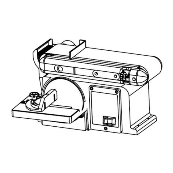
Know your belt/disc sander... -
Page 10: Assembly And Adjustments
Assembly and adjustments WARNING! Always ensure the sander is unplugged prior to attempting any assembly, installation or changing of parts and accessories. Unpacking WARNING: To avoid injury from accidental starting, turn switch OFF and remove plug from power source outlet before making any adjustments. Carefully unpack the belt/disc sander and all its parts, and compare against the list below. - Page 11 Assembly and adjustments (continued) Installation of Sanding Disc and Guard 1. Peel backing away from sanding disc. 2. Align perimeter of disc with plate, and press disc firmly into position on plate, leaving no loose edges. 3. Position disc guard against lower 1/3 of disc, aligning holes as shown. And use a screwdriver to fasten the provided screws and washers securely.
- Page 12 Assembly and adjustments (continued) 3. Adjust the table so that the edge is a maximum of 1/16 inch from the disc. Holding the table in this position, tighten the three bolts on the top of the table. Note: The table may have to be re-adjusted when tilted. WARNING: To avoid trapping the workpiece or fingers between the table and the sanding disc, the table edge should be adjusted to a maximum of 1/16 inch from the sanding disc.
- Page 13 Assembly and adjustments (continued) Mounting the Sander to the Workbench CAUTION: If during operation there is any tendency for the sander to tip over, slide or walk on the supporting surface, the sander should be properly mounted to a workbench or stand. 1.
- Page 14 Assembly and adjustments (continued) Sanding belt tracking adjustment 1. Plug in the power cord. 2. Turn the switch ON and OFF to make sure the sanding belt is correctly centered and not sliding off the idler and drive roller drums. a.
- Page 15 Assembly and adjustments (continued) Install a sanding disc 1. Remove the two screws from the sanding disc guard and remove the guard. 2. Remove the used sanding disc. 3. Wipe the sanding disc plate clean. 4. Peel the backing from the new sanding disc, align the disc with the plate and press the sanding disc firmly on to the plate.
- Page 16 Assembly and adjustments (continued) Square the tables To ensure accurate end sanding, the work tables must be square to the sanding surfaces prior to using the tables for disc sanding. 1. Adjust the table to be 90° with the sanding surface. 2.
-
Page 17: Operation
Operation ON/OFF Switch The keyed switch is intended to prevent unauthorized use of the sander. WARNING: Remove the safety key whenever the sander is not in use. Place the key in a safe place and out of the reach of children. 1. - Page 18 Operation (continued) End sanding and outside curve sanding with the disc Use for sanding the ends of small and narrow workpieces and outside curved edges. Always work on the left side of the disc (downward rotation side), holding the workpiece firmly with light pressure against the sanding disc.
- Page 19 Operation (continued) Miter gauge – Disc sander A miter-gauge is supplied with your sander, and can be used on the disc table. The miter gauge head can be set anywhere up to 60º (right or left) by loosening the lock-knob, setting the miter gauge head to the desired angle, and retightening the lock-knob.
-
Page 20: Maintenance
Maintenance (continued) Adjust the Drive belt 1. Remove the drive belt housing cover (1). 2. Loosen the 3 screws (2) allowing the pulley to slip and the drive belt (3) to loosen. The drive belt should be seated correctly in the motor pulley and the drive pulley. 3. -
Page 21: Troubleshooting
Troubleshooting Service on these tools should only be performed by an authorized, qualified technician. Problem Cause Solution Sanding Grains easily 1. Sanding belt/disc has been 1. Ensure sanding accessories are rub off belt or discs. stored in an incorrect stored away from extremely environment. - Page 22 Problem Cause Solution Motor 1. Motor overloaded. 1. Reduce load on motor (pressure on overheats. 2. Extension cord too long object being sanded). and of insufficient gauge 2. Utilize an extension cord of appropriate (weight). gauge and length or plug tool directly into outlet.
-
Page 23: Exploded View And Parts List
Exploded view and parts list... - Page 24 Exploded view and parts list (continued) Item # Stock # Description Item # Stock # Description 90228-001 Screw M4x6 90228-047 Screw M5x16 90228-002 Flat Washer 4 90228-048 Adjust Knob 90228-003 Base Cover 90228-049 Flat Washer 6 90228-004 Screw ST4.2x10 90228-050 Rubber Washer 90228-005 Lock Washer 4...
-
Page 25: Warranty
Warranty ® PERFORMAX (4" x 36" BELT/ 6" DISC SANDER) WARRANTY 30-DAY MONEY BACK GUARANTEE: ® This brand power tool carries our 30-Day Money Back Guarantee. If you are not PERFORMAX ® completely satisfied with your brand power tool for any reason within thirty (30)
Need help?
Do you have a question about the 240-2973 and is the answer not in the manual?
Questions and answers
I need a safety key where can I get one
The safety key for Performax part number 240-2973 can be obtained by contacting the customer help line at (888) 315-3080, Monday through Friday, 8 AM to 5 PM CST.
This answer is automatically generated