Table of Contents
Advertisement
Advertisement
Table of Contents

Related Manuals for Atag Blauwe Engel S-HR Series


Summary of Contents for Atag Blauwe Engel S-HR Series
- Page 1 These instructions to be retained by user. CE PIN 0063AS3538...
-
Page 3: Table Of Contents
Contents Introduction ..............................4 Regulations ..............................4 Description of the appliance ........................5 Scope of the supply ............................ 5 Mounting of the boiler ..........................5 Dimensions ............................6 Connecting the boiler ..........................7 Central heating system ........................8 Expansion vessel ..........................9 Underfloor heating systems (plastic pipes) .................. -
Page 4: Introduction
Separate instructions for use are supplied with the unit for users of The ATAG Blauwe Engel is a central heating unit with an ATAG central heating units. ATAG is not liable for the optional integrated hot water function. These units must... -
Page 5: Description Of The Appliance
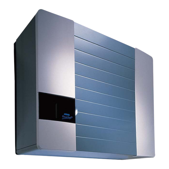
Scope of the supply Description of the appliance The boiler is supplied ready for use. The supply kit is The ATAG Blauwe Engel S-HR boiler is a room sealed, composed as follows: condensing and modulating central heating boiler, with Boiler with casing;... -
Page 6: Dimensions
5.1 Dimensions table 1 Dimensions (* see figure 2) ceiling S R Q figure 1 Dimensions (in mm) Installation instructions S-HR series page 6... -
Page 7: Connecting The Boiler
½ i " ½ i " ½ i " ½ i " ½ i " ¾ i " ¾ i " ¾ i " table 2 connection diameters Connecting the boiler The boiler has the following connection pipes; The central heating pipes. These can be connected to the installation by means of compression fittings;... -
Page 8: Central Heating System
6.1 Central heating system If an unacceptable temperature is detected, then the control will repeatedly try to achieve water flow, and if this The boiler pipes can be connected to the installation by does not work then the boiler will switch off. means of compression fittings. -
Page 9: Expansion Vessel
If the S-HR When using more than one boiler in an installation boiler is provided with a ATAG Comfort cylinder the overall please refer to the cascade installation instructions. depth will be equal. The content of the two expansion vessels is 20 litres. -
Page 10: Underfloor Heating Systems (Plastic Pipes)
figure 5 expansion vessel module The space which is required for mounting the expansion figure 7 side view of the module with S-HR boiler vessel module corresponds with the required space for (dimensions in mm) mounting an S-HR boiler. They included template and 6.3 Underfloor heating system (plastic pipes) mounting strip for the S-HR boiler which can be used for the expansion vessel module. -
Page 11: Gas Connection
6.4 Gas connection 6.6 Hot water supply S-HR 15, 24 and 35 The appliance pipe is fitted with an internal thread, into Depending of the comfort preferences different external hot which the tail piece of the gas tap can be screwed. water cylinders can be connected to the boiler. -
Page 12: Flue Gas Exhaust System And Air Supply System
6.7 Flue gas exhaust system and air supply We recommend that you use a stainless steel flue gas outlet material. Using the ATAG icicle-free roof outlet system prevents ice from building up on the roof outlet. The appliance connection diameter is 80 mm, to which Flue systems must comply with the current regulations. - Page 13 In cold and/or humid weather water vapour may condense on leaving the flue terminal. The effect of such ‘steaming’ must be considered. The terminal must not be located in a place where it is likely to cause a nuisance. For protection of combustibles, refer to IS 813 section 9.10.1.
-
Page 14: External Hot Water Cylinders
All connections should be designed in accordance with the enclosed regulations.; Should it be necessary to change it, the mains power supply cable may only be replaced with an ATAG mains power supply cable (item No. S4407300). The ATAG room thermostat and controls must be connected to their allocated connections. - Page 15 Installation instructions S-HR series page 15...
-
Page 16: Boiler Controls
9.1 Explanation of the function keys Boiler controls Key functions from the and the extensive The boiler is provided with a fully automatic micropro- indication are: cessor control. This control simplifies operation by undertaking all major control functions. Initially when Central Heating program key, see chapter power to the unit is switched on it will remain on standby. -
Page 17: Filling And Venting The Boiler And Installation
Activate the automatic venting program by pressing 10 Filling and venting the boiler the pump key which means the pump lamp will be and installation illuminated. Allow the control to finish its venting program. The pump will circulate a number of times Filling of the system is carried out in the normal way. -
Page 18: Commissioning The Boiler
11.3 Adjustments 11 Commissioning the boiler In the Control Tower a number of adjustments can be Before the boiler is fired, ensure that the boiler and the made. These adjustments can be fed in easily by means system are well vented and free of air. Purge the gas line of the keys on the boiler. - Page 19 ° 5 o l f o l f ° 0 n i l ° 4 * ATAG Brain thermostat l a i ° 4 Most of the adjustments which are stated in l u f o l f tables 7 and 8 are unnecessary when in o l f °...
- Page 20 Installers adjustments Adjustments whereby technical knowledge is required have been classified under the installers level. Access to this level is obtained after feeding in a code, after which adjustments for user and installer are visible. For going to the “Adjustments Parameters” chapter the Mode key should be pressed once after which it is shown with the text.
-
Page 21: Isolating The Boiler
Service chapter. Green key function After the access code has been fed in it is possible to The green key function can be used in order to activate the temporarily manually adjust the number of revolutions factory settings. By this means the modified settings are of the fan in the service chapter (table 10). -
Page 22: Commissioning
connect the digital pressure gauge hose to the 13 Commissioning uppermost measuring nipple of the gas block according to figure 12(open it before fitting the hose); The top of the casing is hooked behind a locking edge and is locked behind the door on the front of the casing with a screw. -
Page 23: Checking The Co
connect the digital pressure gauge hose to the 13.3 Checking the CO uppermost measuring nipple of the gas block The CO percentage is factory-set. This can be checked according to figure 13; by means of the following actions: activate the manual control by briefly pressing the put the boiler into operation by means of the service “-”... -
Page 24: Maintenance
The following components require extra attention during the 14 Maintenance service procedure and when dismantling and reassenbling the burner: Maintenance or changes to the unit may only ensure that the orange gasket that fits around the be carried out by an authorised technician. ceramic brick has not heat hardened or perished in any way, if it has, it is essential that the gasket is replaced before continuing to reassemble the boiler. -
Page 25: Technical Specifications
15 Technical specifications a i l ° 0 ° 0 ° 0 ° 0 ° 0 ° ° 0 ° o i t ° 0 ³ ° ° 0 ° 5 a l i a i l ° 0 ° 0 ³... -
Page 26: Diagram Showing Various Parts Of The Boiler
16 Diagram showing various parts of the boiler figure 16 boiler diagram G gas pipe A flow connection central heating R return connection central heating C condensation pipe E expansion vessel (only S-HR 24T and 35T) expansion vessel pipe (only S-HR 51T) K cold water pipe (S-HR-T) W hot water pipe (S-HR-T) T1 flow sensor... - Page 27 C 11 13 14 figure 17 boiler description Control Tower heat exchanger water filter return central heating ignition unit three-way valve (S-HR-T) fan unit circulation pump air inlet damper thermostatic mixing valve (S-HR-T) gas block flue gas discharge safety valve combustion air supply automatic air vent air unit...
-
Page 28: Example Diagrams For Connecting The Boiler
17 Example diagrams for connecting the boiler 17.1 Radiator installation without thermostat valves figure 18 connecting of the boiler to a radiator installation without thermostat valves 1 ATAG Blauwe Engel S-HR boiler 2 expansion vessel 3 outside sensor ARV1215U 4 drain points... -
Page 29: Radiator Installation With Thermostat Valves Only
17.2 radiator installation with thermostat valves only figure 19 connecting of the boiler to a radiator installation with thermostat valves only 1 ATAG Blauwe Engel S-HR boiler 2 expansion vessel 3 outside sensor ARV1215U 4 drain points 5 ATAG room thermostat... -
Page 30: Error Indication
18 Error indication When detected, errors are indicated on the display. Some, of a temporary nature, will not usually result in the boiler locking out. Whilst the control system will try its utmost to prevent lockout, and may temporarily switch off the unit, any fault which could potentially damage the appliance will result in lockout. -
Page 31: Ce-Certificate United Kingdom
19 CE-Certificate United Kingdom Installation instructions S-HR series page 31... -
Page 32: Ce-Certificate Ireland
20 CE-Certificate Ireland Installation instructions S-HR series page 32... - Page 36 This renewed publication cancels all previous installation instructions. The company reserves the right to change the specifications and dimensions without prior notice E. & O. E.
- Page 37 Ignition phase Burner active on central heating Burner active on hot water Fan check Distributor for UK ATAG Heating UK Ltd. Burner off when room thermostat is demanding Unit M1 Pump overrun phase for central heating Hilton Business Park Pump overrun phase for hot water...
Need help?
Do you have a question about the Blauwe Engel S-HR Series and is the answer not in the manual?
Questions and answers