Table of Contents
Advertisement
Available languages
Available languages
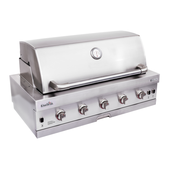
M E DALLION B U I LT-I N G RI LL
4 & 5 B U RN E R
M E DALLION PARRI LLA I NCORP ORADA
4 y 5 QU E MADOR
If you have questions or need assistance during assembly, please call 1-800-448-2177
Si tiene alguna pregunta o si Necesita ayuda durante el Ensamblado, llámenos Al 1-800-448-2177
9/13/18 • G622-001-010801
463277519
463278519
©
2018 Char-Broil, LLC. Columbus, GA, 31904. Printed in China. Imprimé en Chine. Impreso en China.
P RODUCT G U I DE
G UíA DE L P RODUCTO
M O D EL
M O D ELO
S E R IAL N U M B E R
NÚ M E R O D E S E R I E
• See rating label on grill for serial number.
• El número de serie se encuentra en la etiqueta
deespecificaciones de la parrilla.
DATE P U R C H AS E D
FE C HA D E C OM P RA
NOTE: If you are planning to convert your grill from Natural Gas to Propane
Gas, it is highly recommended that you perform the conversion BEFORE grill
installation.
NOTA: Si planea convertir su parrilla de Gas Natural a Gas Propano, se
recomienda encarecidamente que realice la conversión ANTES de la insta-
lación de la parrilla.
CONVERSION KIT | KIT DE CONVERSION
#2429018
1
463277519
463278519
Easily converts from (NG) Natural Gas to (LP) liquid propane.
Se convierte fácilmente de (NG) gas natural a (LP) propano líquido.
Advertisement
Table of Contents

Related Manuals for Char-Broil 463278519


Summary of Contents for Char-Broil 463278519
- Page 1 If you have questions or need assistance during assembly, please call 1-800-448-2177 Si tiene alguna pregunta o si Necesita ayuda durante el Ensamblado, llámenos Al 1-800-448-2177 9/13/18 • G622-001-010801 © 2018 Char-Broil, LLC. Columbus, GA, 31904. Printed in China. Imprimé en Chine. Impreso en China.
- Page 2 PAG E 11 DANGER: Indicates a imminently hazardous situation which, if notavoided, will result in death or serious injury. RE PLACE M E NT PARTS DIAG RAM - 463278519 PAG E 22 RE PLACE M E NT PARTS LIST - 463278519...
- Page 3 FOR YOU R SAFETY - I NSTALLI NG YOU R G RI LL W A R N I N G W A R N I N G D A N G E R • Keep grill area clear and free from materials that Perform the following checks prior to the first •...
-
Page 4: Grill Installation
It is best to identify the location Grill Model Dim. A Dim. B Dim. C Dim. D Dim. E of the grill prior to beginning any set up. 463278519 34 7/8” 21.5/8” 11” 14 9/16” 33 7/16” 4 Burner 885mm... - Page 5 Note that this regulator can not be used for LP (propane) C A U T I O N The grill model 463278519 and model 463277519 are set for use with natural Grill shown installed in island gas. Both appliances are designed for conversion to LP gas also. CONVERSION ELECTRONIC CONTROL MODULE: TO LP GAS MUST BE PERFORMED BY A CERTIFIED GAS TECHNICIAN.
- Page 6 PLAN N I NG FOR I NSTALLATION enclosure. This allows for easy access to connect the gas piping in the enclosure AFTER INSTALLING THE GRILL IN THE ENCLOSURE: to the shut-off valve. If a gas supply stub-up is used inside the grill enclosure, 1.
- Page 7 LEAK CH ECKI NG YOU R G RI LL Le a k Testin g Turn all grill control knobs to OFF. Turn ON the home gas source. Use a clean paint brush and a 50/50 mild soap and water solution. Brush soapy solution onto areas indicated. (see Figure C). If “growing”...
- Page 8 FOR YOU R SAFETY - WH I LE OPE RATI NG YOU R G RI LL Before each use of your Grill: W A R N I N G C A U T I O N Perform a Valve Check For Safe Use of Your Grill and to Avoid •...
- Page 9 FOR YOU R SAFETY - LIG HTI NG YOU R G RI LL LIG HTI NG TH E MAI N BU RN E RS Main Burner Ignitor Lighting Main Burner Match-Lighting • Do not lean over the grill while lighting. •...
- Page 10 CARE AN D MAI NTE NANCE OF YOU R G RI LL C l e a n i n g t h e B u r n e r A s s e m b l y Follow these instructions to clean and/or replace parts of burner assembly or if you FIREBOX have trouble igniting griddle.
- Page 11 G RI LL LIG HTS - OPE RATION AN D BU LB RE PLACE M E NT Ligh t Operatio n • If your grill is hot, make sure the grill has been turned OFF and allowed to cool. • Ensure the Grill Light Switch is in the OFF position.
- Page 12 LLAS PÁGINA 21 PELIGRO: Indica una situación inminentemente peligrosa que, si no se evita, ocasionará la muerte o lesiones graves. DIAGRAMA DE PIEZAS DE REPUESTO - 463278519 PÁGINA 22 LISTA DE PIEZAS DE REPUESTO - 463278519 PÁGINA 24 P E L I G R O...
- Page 13 PARA SU SEG U RI DAD, I NSTALACIÓN DE SU PARRI LLA A D V E R T E N C I A A D V E R T E N C I A P E L I G R O •...
- Page 14 Modelo de parrilla Dim. A Dim. B Dim. C Dim. D Dim. E aire libre. Lo mejor es identificar la ubicación de la parrilla antes de comenzar cualquier 463278519 34 7/8” 21.5/8” 11” 14 9/16” 33 7/16” preparación. 4 quemadores...
- Page 15 2 y 5 psi. Con este cambio también se requirió que se de BTU de la parrilla es de 40,000 BTU/h para el modelo 463278519 y de 45,000 BTU/h conectara un regulador en línea entre el regulador de servicio y el regulador del aparato si para el modelo 463277519.
- Page 16 PLAN I FICACIÓN PARA LA I NSTALACIÓN posterior del gabinete de la parrilla. Esto permite un acceso fácil para conectar la tubería DESPUÉS DE INSTALAR LA PARRILLA EN EL RECINTO: de gas en el gabinete a la válvula de cierre. Si se usa un conector de suministro de gas 1.
- Page 17 CONTROLAR LAS FUGAS DE SU PARRI LLA P r u e b a d e f u g a s Gire todas las perillas de control de la parrilla a la posición OFF. Encienda la fuente de gas del hogar. Use un pincel limpio, y una solución de agua y jabón suave 50/50.
- Page 18 PARA SU SEG U RI DAD, OPE RAR SU PARRI LLA Antes del cada uso de la parrilla: A D V E R T E N C I A P R E C A U C I Ó N Realice un control de válvula Para un uso seguro de su parrilla y para •...
- Page 19 PARA SU SEG U RI DAD, E NCE N DE R SU PARRI LLA E NCE N DI DO DE LOS QU E MADORES PRI NCI PALES Encendido del encendedor del quemador principal Encendido con cerillo del quemador principal • No se incline sobre la parrilla mientras se enciende. •...
- Page 20 CU I DADO Y MANTE N I M I E NTO DE SU PARRI LLA Limpieza del conjunto de quemadores. CÁMARA DE COMBUSTIÓN Siga estas instrucciones para limpiar y/o reemplazar partes del conjunto del quemador o si tiene problemas para encender la plancha. 1 .
- Page 21 LUCES DE LA PARRILLA - FUNCIONAMIENTO Y SUSTITUCIÓN DE BOMBILLAS Operación de las luces • Si su parrilla está caliente, asegúrese de que la parrilla se haya colocado en la posición OFF y se haya dejado enfriar. • Asegúrese de que el Interruptor de luz de la parrilla esté en la posición de OFF. •...
- Page 22 ASSEMBLY REPLACEMENT PARTS DIAGRAM - 463278519 C H A R B R O I L . C O M C H A R B R O I L . C O M P a g e 2 2 P a g e 2 2...
- Page 23 REPLACEMENT PARTS LIST - 463278519 Key Qty Description Key Qty Description FIREBOX FRAME TOP LID ROTISSERIE BRACKET SUPPORT TEMPERATURE GAUGE CONTROL PANEL BEZEL, F/ TEMPERATURE GAUGE HOSE VALVE ASSEMBLY LOGO PLATE BEZEL F/ CONTROL KNOB HANDLE F/ LID STOP PIN, F/ NG...
- Page 24 ASSEMBLY LISTA DE PIEZAS DE REPUESTO - 463278519 Llave Cantidad Descripción Llave Cantidad Descripción MARCO DE FUEGO TAPA SUPERIOR SOPORTE SOPORTE ROTISSERIE INDICADOR DE TEMPERATURA PANEL DE CONTROL BISEL, F / MEDIDOR DE TEMPERATURA CONJUNTO DE VÁLVULA DE MANGUERA PLACA DE LOGOTIPO...
- Page 25 REPLACEMENT PARTS DIAGRAM - 463277519 C H A R B R O I L . C O M P a g e 2 5...
- Page 26 REPLACEMENT PARTS LIST - 463277519 Key Qty Description Key Qty Description FIREBOX FRAME TOP LID ROTISSERIE BRACKET SUPPORT TEMPERATURE GAUGE CONTROL PANEL BEZEL, F/ TEMPERATURE GAUGE HOSE VALVE ASSEMBLY LOGO PLATE BEZEL F/ CONTROL KNOB HANDLE F/ LID STOP PIN, F/ NG FRONT BUMPER, F/ TOP LID CONTROL KNOB TOP LID HARDWARE...
- Page 27 LISTA DE PIEZAS DE REPUESTO - 463277519 Clave Cant. Descripción Clave Cant. Descripción BASTIDOR DE LA CÁMARA DE COMBUSTIÓN TAPA SUPERIOR SOPORTE DE LA CÁMARA DEL ASADOR INDICADOR DE TEMPERATURA BISEL, PARA INDICADOR DE TEMPERATURA PANEL DE CONTROL PLACA DE LOGOTIPO CONJUNTO DE VÁLVULA DE LA MANGUERA MANIJA PARA TAPA BISEL, PARA PERILLA DE CONTROL...
- Page 28 ASSEMBLY / MONTAJE - 463278519 C H A R B R O I L . C O M P a g e 2 8...
- Page 29 ASSEMBLY / MONTAJE - 463278519 C H A R B R O I L . C O M P a g e 2 9...
- Page 30 ASSEMBLY / MONTAJE - 463278519 C H A R B R O I L . C O M P a g e 3 0...
- Page 31 ASSEMBLY / MONTAJE - 463278519 Blue/Azul Red/Rojo C H A R B R O I L . C O M P a g e 3 1...
- Page 32 ASSEMBLY / MONTAJE - 463277519 C H A R B R O I L . C O M P a g e 3 2...
- Page 33 ASSEMBLY / MONTAJE - 463277519 C H A R B R O I L . C O M P a g e 3 3...
- Page 34 ASSEMBLY / MONTAJE - 463277519 C H A R B R O I L . C O M P a g e 3 4...
- Page 35 ASSEMBLY / MONTAJE - 463277519 Blue/Azul Red/Rojo C H A R B R O I L . C O M P a g e 3 5...
- Page 36 ASSEMBLY / MONTAJE - 463277519 and 463278519 Securing your grill to your enclosure Asegurando su parrilla a su recinto Place your grill into the enclosure and ensure it is in it' s final location. Coloque su parrilla en el gabinete y asegúrese de que esté en su Using the included L-brackets, place one of the brackets into location ubicación final.
-
Page 37: Troubleshooting
TROU BLESHOOTI NG EMERGENCIES: If a gas leak cannot be stopped, or a fire occurs due to gas leakage, call the fire department. EMERGENCIES POSSIBLE CAUSE PREVENTION / SOLUTION • • Gas leaking from cracked/cut/burned hose. Damaged hose. Turn off gas at source on natural gas system or at LP cyl- inder. - Page 38 TROU BLESHOOTI NG PROBLEM POSSIBLE CAUSE PREVENTION / SOLUTION ELECTRONIC IGNITION: Burner(s) will not light using ignitor. • • See Section I of Electronic Ignition System. (See Electronic Ignition Troubleshooting also) No spark, no ignition noise. • • See Section II of Electronic Ignition System. Continued on next page.
- Page 39 SOLUCIÓN DE PROBLE MAS EMERGENCIAS: Si no se puede detener una fuga de gas, o si se produce un incendio debido a una fuga de gas, llame al departamento de bomberos. E M E R G E N C I A S C A U S A P O S I B L E P R E V E N C I Ó...
- Page 40 SOLUCIÓN DE PROBLE MAS P R O B L E M A C A U S A P O S I B L E P R E V E N C I Ó N / S O L U C I Ó N ENCENDIDO ELECTRÓNICO: Los quemadores no se encienden con el encendedor.
- Page 41 LI M ITE D WARRANTY This warranty only applies to units purchased from an authorized retailer. Manufacturer warrants to the original consumer-purchaser only that this product shall be free from defects in workmanship and materials after correct assembly and under normal and reasonable home use for the periods indicated below beginning on the date of purchase*. The manufacturer reserves the right to require that defective parts be returned, postage and or freight pre-paid by the consumer for review and examination.
- Page 42 GARANTÍA LI M ITADA Esta garantía solo se aplica a las unidades compradas en un minorista autorizado. El fabricante únicamente garantiza al comprador-consumidor original que este producto estará libre de defectos materiales y de materiales después de corregir el montaje y bajo uso doméstico normal y razonable durante los periodos indicados a continuación a partir de la fecha de la compra*.
- Page 43 Mail to: | Envoyer à: | Correo a: privacidad Char-Broil Warranty Registration P.O. Box 1240 If you prefer not to receive special offers and promotions from Char-Broil, please Columbus, Ga 31902-1240 check here: Si vous préférez recevoir des offres et promotions spéciales de Char-Broil, veuillez vérifier ici:...
- Page 44 2017 Instrucciones de ensamblado. © © The product associated with this guide was manufactured in China. Tel producto asociado con esta guía ha sido fabricado en China. 2018 Char-Broil, LLC. Columbus, GA, 31904. Printed in China. Imprimé en Chine. Impreso en China. ©...
Need help?
Do you have a question about the 463278519 and is the answer not in the manual?
Questions and answers