Table of Contents
Advertisement
Quick Links
Advertisement
Table of Contents

Related Manuals for ESD CAN-USB/2

Summary of Contents for ESD CAN-USB/2
- Page 1 CAN-USB/2 Hardware Manual • Doc. No.: C.2066.21 / Rev. 1.6 Page 1 of 28 esd electronics gmbh Vahrenwalder Str. 207 • 30165 Hannover • Germany http://www.esd.eu Phone: +49 (0) 511 3 72 98-0 • Fax: +49 (0) 511 3 72 98-68...
- Page 2 design.
- Page 3 Date of print: 2019-06-17 Document type DOC0800 number: PCB version: CAN-USB/2 Rev. 1.2 Document History The changes in the document listed below affect changes in the hardware as well as changes in the description of the facts, only. Revision Chapter...
-
Page 4: Safety Instructions
This NOTICE statement contains the general mandatory sign and gives information that must be heeded and complied with for a safe use. INFORMATION INFORMATION Notes to point out something important or useful. Page 4 of 28 Hardware Manual • Doc. No.: C.2066.21 / Rev. 1.6 CAN-USB/2... - Page 5 ● When working with the CAN-USB/2 follow the instructions below and read the manual carefully to protect yourself from injury and the CAN-USB/2 from damage. ● Do not use damaged or defective cables to connect the CAN-USB/2 and follow the CAN wiring hints in chapter: "Correct Wiring of Electrically Isolated CAN Networks".
-
Page 6: Table Of Contents
Grounding......................24 Short Circuit in CAN Wiring....................24 CAN_H/CAN_L-Voltage ......................24 CAN Transceiver Resistance Test..................25 Support by esd........................25 8. License............................26 Declaration of Conformity......................27 Order Information........................28 Page 6 of 28 Hardware Manual • Doc. No.: C.2066.21 / Rev. 1.6... -
Page 7: Overview
LEDs Figure 1: Block-circuit diagram of CAN-USB/2 module The CAN-USB/2 module is an intelligent CAN interface with an ARM7 micro controller for local CAN data management. The module supports the USB 2.0 Hi-Speed interface with data transfer rates of 480 Mbit/s. -
Page 8: Case View With Led And Connector Description
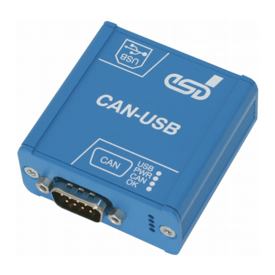
Case View with LED and Connector Description 2. Case View with LED and Connector Description Figure 2: CAN connector and LEDs Figure 3: USB Interface CAN-USB/2 Hardware Manual • Doc. No.: C.2066.21 / Rev. 1.6 Page 9 of 28... -
Page 9: Led-Displays
CAN interface is initialized and in mode “Automatic slow flashing Baud rate Detection” (from firmware version 1.0.0.4 (approx. 1 Hz) and CAN driver version 2.5.2 on) Table 1: Description of LED display Page 10 of 28 Hardware Manual • Doc. No.: C.2066.21 / Rev. 1.6 CAN-USB/2... -
Page 10: Hardware Installation
Read the safety instructions at the beginning of this document carefully, before you start with the hardware installation! Connect the CAN bus via the DSUB9 connector of the CAN-USB/2 as described in chapter “Correctly Wiring Electrically Isolated CAN Networks“. -
Page 11: Technical Data
4.2 USB Interface and Microcontroller USB interface USB 2.0, bit rate up to 480 Mbit/s Microcontroller ARM7 microcontroller Table 3: USB interface and microcontroller Page 12 of 28 Hardware Manual • Doc. No.: C.2066.21 / Rev. 1.6 CAN-USB/2... -
Page 12: Can Interface
4.4 Software Support Device drivers for Windows ® and Linux ® are available. Drivers for other operating systems, especially real-time operating systems, are available on request. CAN-USB/2 Hardware Manual • Doc. No.: C.2066.21 / Rev. 1.6 Page 13 of 28... -
Page 13: Connector Assignments
CAN physical layer of CAN interface x (x... 1 - 4) Shield ... shielding (connected with the case of the DSUB9 connector and with the case of the CAN-USB/2) - ... reserved for future applications, do not connect! Page 14 of 28 Hardware Manual •... -
Page 14: Usb Socket
USB signal lines Data+ and Data- GND... Reference potential Shield ... shielding (connected with the case of the USB connector and with the case of the CAN-USB/2) CAN-USB/2 Hardware Manual • Doc. No.: C.2066.21 / Rev. 1.6 Page 15 of 28... -
Page 15: Correctly Wiring Electrically Isolated Can Networks
Therefore the practical maximum number of nodes, bus length and stub length are typically much lower. esd has concentrated her recommendations concerning CAN wiring on the specifications of the ISO 11898-2. Thus this wiring hints forgoes to describe the special features of the derived standards CANopen, ARINC825, DeviceNet and NMEA2000. -
Page 16: Light Industrial Environment (Single Twisted Pair Cable)
6.2.1 General Rules NOTICE esd grants the EU Conformity of the product, if the CAN wiring is carried out with at least single shielded single twisted pair cables that match the requirements of ISO 11898-2. Single shielded double twisted pair cable wiring as described in chapter 6.3. ensures the EU Conformity as well. -
Page 17: Cabling
9-pin DSUB-termination connectors with integrated termination resistor and male and ● female contacts are available from esd (order no. C.1303.01). DSUB termination connectors with male contacts (order no. C.1302.01) or female contacts ● (order no. C.1301.01) and additional functional earth contact are available, if CAN termination and grounding of CAN_GND is required. -
Page 18: Heavy Industrial Environment (Double Twisted Pair Cable)
CAN_L CAN_GND wire shield n.c. n.c. connector case connector case Shield n.c. = not connected earth (FE) Figure 6: CAN wiring for heavy industrial environment CAN-USB/2 Hardware Manual • Doc. No.: C.2066.21 / Rev. 1.6 Page 19 of 28... -
Page 19: Device Cabling
CAN bus line via short cable stubs. This is normally realised by so called T- connectors. When using esd's CAN-T-Connector (order no.: C.1311.03) it should be noted that the shield potential of the conductive DSUB housing is not looped through this T- Connector type. -
Page 20: Electrical Grounding
5000 Table 5: Recommended cable lengths at typical bit rates (with esd-CAN interfaces) Optical couplers are delaying the CAN signals. esd modules typically reach a wire length of ● 37 m at 1 Mbit/s within a proper terminated CAN network without impedance disturbances like e.g. -
Page 21: Examples For Can Cables
Correctly Wiring Electrically Isolated CAN Networks 6.6 Examples for CAN Cables esd recommends the following two-wire and four-wire cable types for CAN network design. These cable types are used by esd for ready-made CAN cables, too. 6.6.1 Cable for light industrial Environment Applications (Two-Wire) -
Page 22: Can Troubleshooting Guide
- there are no open circuits in CAN_H or CAN_L wiring - your bus system has two terminating resistors (one at each end) and that they are 120 Ω each. CAN-USB/2 Hardware Manual • Doc. No.: C.2066.21 / Rev. 1.6 Page 23 of 28... -
Page 23: Electrical Grounding
(see figure at previous page). 4. Measure the DC voltage between CAN_L and CAN_GND (see figure at previous page). Normally the voltage should be between 2.0 V and 3.0 V. Page 24 of 28 Hardware Manual • Doc. No.: C.2066.21 / Rev. 1.6 CAN-USB/2... -
Page 24: Can Transceiver Resistance Test
If you have executed the fault diagnostic steps of this troubleshooting guide and you even can not find a solution for your problem our support department will be able to assist. Please contact our support via email at support@esd.eu or by phone +40-511-37298-130. CAN-USB/2 Hardware Manual •... -
Page 25: License
8. License The CAN-USB/2 uses the open source FreeRTOS operating system. For the full license text please see esd's "3rd party licensor notice" document that is part of the product's documentation on the enclosed CD. Page 26 of 28 Hardware Manual • Doc. No.: C.2066.21 / Rev. 1.6... -
Page 26: Declaration Of Conformity
Declaration of Conformity 9. Declaration of Conformity CAN-USB/2 Hardware Manual • Doc. No.: C.2066.21 / Rev. 1.6 Page 27 of 28... -
Page 27: Order Information
- CAN-Data rate up to 1 MBit/s - integrated Firmware - Powering via USB Each CAN-USB/2 type includes a CD-ROM with CAN layer 2 software driver for Windows and Linux, demo programs and tools as well as documentation and manuals. Software...
Need help?
Do you have a question about the CAN-USB/2 and is the answer not in the manual?
Questions and answers