Table of Contents
Advertisement
Quick Links
1484450/3
CA44, CA44S, CA46 and CA46S
Installation and Maintenance Instructions
IM-P148-37 ST Issue 3
Air and Gas Traps
IM-P148-37
1. Safety information
2. General
product information
3. Installation
4. Commissioning
5. Operation
6. Maintenance
7. Spare parts
© Copyright 2015
ST Issue 3
1
Printed in GB
Advertisement
Table of Contents

Related Manuals for Spirax Sarco CA44


Summary of Contents for Spirax Sarco CA44
- Page 1 IM-P148-37 1484450/3 ST Issue 3 CA44, CA44S, CA46 and CA46S Air and Gas Traps Installation and Maintenance Instructions 1. Safety information 2. General product information 3. Installation 4. Commissioning 5. Operation 6. Maintenance 7. Spare parts © Copyright 2015 IM-P148-37 ST Issue 3...
-
Page 2: Safety Information
Determine the correct installation situation and direction of fluid flow. iv) Spirax Sarco products are not intended to withstand external stresses that may be induced by any system to which they are fitted. It is the responsibility of the installer to consider these stresses and take adequate precautions to minimise them. -
Page 3: Protective Clothing
1.8 Temperature Allow time for temperature to normalise after isolation to avoid danger of burns. Viton - CA44 and CA46 main valve cone: If the the main valve cone (made of Viton) has been subjected to a temperature approaching 315°C (599°F) or higher it may have decomposed and formed hydrofluoric acid. -
Page 4: Residual Hazards
1.16 Returning products Customers and stockists are reminded that under EC Health, Safety and Environment Law, when returning products to Spirax Sarco they must provide information on any hazards and the precautions to be taken due to contamination residues or mechanical damage which may present a health, safety or environmental risk. -
Page 5: General Description
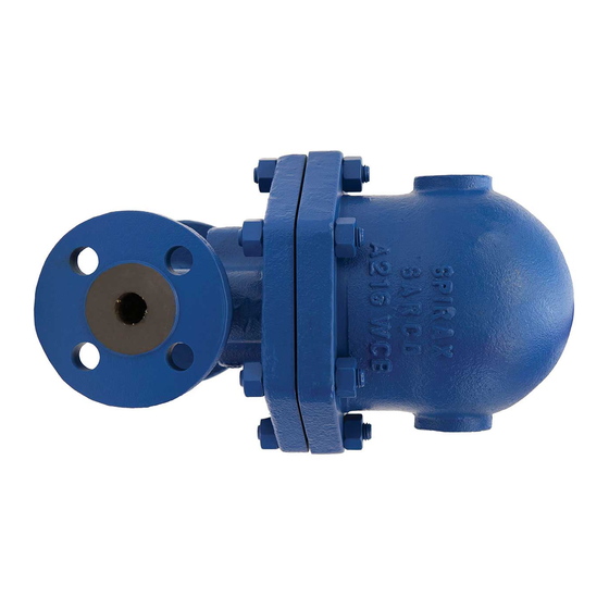
DN15 and DN20 Flanged The CA44 is a carbon steel ball float air and gas trap. It is available with a soft valve cone and has horizontal flanged connections. The cover will be drilled and tapped ½" BSP or NPT for the purpose of fitting a balance line. - Page 6 2.2 CA44 and CA44S - Carbon steel Fig. 1 CA44 and CA44S DN15 and DN20 DIN flange Fig. 2 CA44S Sizes and pipe connections DN40 and DN50 DIN flange CA44 DN15 and DN20 flanged CA44S 1" screwed BSP or NPT with BSP or NPT balance line.
-
Page 7: Operating Range
Operating range CA44 Pressure bar g CA44S Pressure bar g The product must not be used in this region. A - B Flanged EN 1092 PN40, ASME 300, screwed and socket weld A - C Flanged JIS / KS 20K A - D Flanged ASME 150 ∆... - Page 8 2.3 CA46 and CA46S - Austenitic stainless steel Fig. 3 CA46 and CA46S DN15 and DN20 DIN flange Fig. 4 CA46S DN40 and DN50 DIN flange Sizes and pipe connections CA46 DN15 and DN20 flanged CA46S DN15, DN20, DN25, DN40 and DN50 flanged Standard flanges are EN 1092 PN40 with DIN face-to-face dimensions and BS 1560 class ASME 150 and ASME 300 and JIS / KS 20K with drilled and tapped bolt holes with DIN face-to-face dimensions.
- Page 9 Operating range CA46 - DN15 and DN20 flanged Pressure bar g CA46S - DN15, DN20 and DN25 flanged Pressure bar g CA46S - DN40 and DN50 flanged Pressure bar g The product must not be used in this region. A - B Flanged EN 1092 PN40 and ASME 300 A - C Flanged ASME 150 (DN15, DN20 and DN25 only) and JIS / KS 20K D - D Flanged ASME 150 (DN40 and DN50 only) ∆...
-
Page 10: Installation
5. Operation The CA44(S) and CA46(S) float traps are continuous discharge traps, removing liquid from air and gas systems. As soon as liquid enters the main chamber of the trap, the float rises and the lever mechanism attached to it opens the main valve - keeping the system drained of liquid at all times. - Page 11 Air receiver Balance line Strainer CA14 air trap draining small receiver Fig. 5 Installation with balance line arrangement IM-P148-37 ST Issue 3...
-
Page 12: Maintenance
Undo the cover bolts (2) and lift off the cover. Remove the float assembly (8 + 9 CA44 and CA46 only) by extracting the pivot pin (16). Remove the support (14), pivot frame (15) and the valve seat (5) by unscrewing the set screws (7). - Page 13 Fig. 6 CA44S and CA46S DN40 and DN50 Note: The trap shown is the DN40 and DN50 CA44S / CA46S. However the type of internals and the method of maintenance is no different from that used in the smaller sizes of CA44(S) and CA46 (S).
-
Page 14: Spare Parts
(packet of 3 sets) 3, 6 *The CA44 and CA46 use a soft Viton valve head, where as the CA44S and CA46S use a stainless steel valve head. Note: The trap shown is the DN40 and DN50 CA44S / CA46S. However the type of internals and the method of maintenance is no different from that used in the smaller sizes of CA44(S) and CA46 (S). - Page 15 DN40 and 50 CA44S and CA46S only 15 14 7 *CA44 and CA46 only Main valve assembly with float Fig. 7 CA44S and CA46S DN40 and 50 (see note under 'Available spares') IM-P148-37 ST Issue 3...
- Page 16 IM-P148-37 ST Issue 3...
Need help?
Do you have a question about the CA44 and is the answer not in the manual?
Questions and answers