Spirax Sarco EasiHeat Installation And Maintenance Instructions Manual
Htg steam side control water heating compact heat transfer solution
Hide thumbs
Also See for EasiHeat:
Table of Contents
Advertisement
Spirax EasiHeat
TM
HTG Steam Side Control Water Heating
Compact Heat Transfer Solution
Installation and Maintenance Instructions
IM-P481-10-US
September 2017
1. Safety information
2. General product
information
3. Installation
4. Commissioning
5. Operation
6. Maintenance
© Copyright 2017
Printed in USA
IM-P481-10-US 9/2017
1
Advertisement
Table of Contents

Related Manuals for Spirax Sarco EasiHeat


Summary of Contents for Spirax Sarco EasiHeat
- Page 1 Spirax EasiHeat HTG Steam Side Control Water Heating Compact Heat Transfer Solution Installation and Maintenance Instructions IM-P481-10-US September 2017 1. Safety information 2. General product information 3. Installation 4. Commissioning 5. Operation 6. Maintenance © Copyright 2017 Printed in USA...
-
Page 2: All Rights Reserved
Copyright © Spirax-Sarco Limited 2017 All rights reserved Spirax-Sarco Limited grants the legal user of this product (or device) the right to use the Work(s) solely within the scope of the legitimate operation of the product (or device). No other right is granted under this licence. -
Page 3: Safety Information
Warning - Lifting The Spirax EasiHeat unit should be lifted by a suitable forklift truck, from the base, placed in position and securely bolted to the floor. On no account is the Spirax EasiHeat unit to be lifted by any other part, other than the base. -
Page 4: Intended Use
Determine the correct installation situation and direction of fluid flow. iv) Spirax Sarco products are not intended to withstand external stresses that may be induced by any system to which they are fitted. It is the responsibility of the installer to consider these stresses and take adequate precautions to minimise them. -
Page 5: Protective Clothing
1.9 Tools and consumables Before starting work ensure that you have suitable tools and / or consumables available. Use only genuine Spirax Sarco replacement parts. 1.10 Protective clothing Consider whether you and / or others in the vicinity require any protective clothing to protect against the hazards of, for example, chemicals, high/low temperature, radiation, noise, falling objects, and dangers to eyes and face. - Page 6 1.11 Permits to work All work must be carried out or be supervised by a suitably competent person. Installation and operating personnel should be trained in the correct use of the product according to the Installation and Maintenance Instructions. Where a formal 'permit to work' system is in force it must be complied with. Where there is no such system, it is recommended that a responsible person should know what work is going on and, where necessary, arrange to have an assistant whose primary responsibility is safety.
-
Page 7: General Product Information
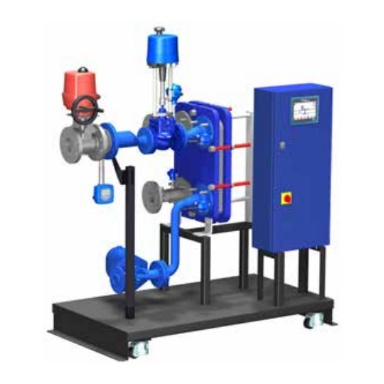
2. General product information 2.1 General information The Spirax EasiHeat HTG system uses steam to provide accurate heating of potable hot water or hot water for processes. Systems are supplied fully assembled and pressure tested ready for installation. and are supplied fully assembled and pressure tested ready for installation. - Page 8 Spirax EasiHeat™ Heating Steam Side Control nomenclature Building EHHSC = Spirax EasiHeat™ Heating EHHSC heating unit Steam Side Control 1" reduced trim Split range: 1" reduced trim & 1" 1" Split range: 1" & 1½" Control 1½" valve size Split range: 1½" & 2"...
- Page 9 110V UL SIMS TOUCH SCREEN Panel type 110V UL PROCESS CONTROLLER Panel Energy E = With energy monitoring options monitoring Level 1 - SMS Text and E-mail Remote Level 2 - 3G web access access Level 3 - Both of the above (R1+R2) Modbus RTU BACnet MS/TP (RS485)
-
Page 10: Installation
The installation of an appropriately sized safety valve, to protect any lower pressured equipment on either the hot or cold side of the plate heat exchanger, is strongly recommended. Spirax Sarco supplies a range of traps, strainers, separators, safety valves and pressure reducing equipment. 3.2 Air supply If a pneumatic control system is installed, connect a compressed air supply (65 to 116 psi g) to the pressure regulator mounted on the control valve. -
Page 11: Electrical Specifications
High limit isolation valve 24 Vac PT100 temperature sensors 3 wire Note: Power supply 10 - 16 A 3.5 Electrical connections The following are available for customer connection to the Spirax EasiHeat system if required: Volt free contacts Terminal designation Description Type... - Page 12 Remote operation and retransmission connections Terminal designation Description Type Remote set point 4-20 mA input Remote enable 24 Vdc signal Retransmission value 4-20 mA output 001- 001+ 24.3 CHANNEL 13 REMOTE SYSTEM CHANNEL 0 4-20mA ENABLE RETRANSMISSION REMOTE PID OF PV OR VALVE Fig.
- Page 13 Terminal layout overview X1 - X5 X6 - X8 X9 - X10A X10B – 10G PT100 4 - 20 mA 4 - 20 mA actuator Bypass inputs inputs outputs signals pump X13A-C X14 - X16 Bypass High limit volt free remote valve valve...
- Page 14 4. Commissioning We strongly recommend that you use the service and support of a Spirax Sarco commissioning engineer. Details of this service can be found by contacting Spirax Sarco. Note: Pre commissioning requirements: In most new installations, dirt collects in the steam pipeline during construction of the system.
- Page 15 Open the secondary (cold side) isolating valves downstream of the Spirax EasiHeat. Start the main secondary water circulating pump(s) if fitted. Check and confirm there is secondary water circulation through the Spirax EasiHeat. If the circulation is okay, switch on the main power to the control panel (local isolator).
- Page 16 TVA flowmeter commissioning chart To navigate around the first level menu use the up and down arrows, to enter any sub menu use the right arrow. Fig. 10 TVA configuration displays Normal run mode Configuration Default = 7452 but user display sequence sub-menus settable.
- Page 17 Fig. 11 PULSE The next menu Sorce will need FLOW to be selected. Obtain the correct flow data from the Spirax EasiHeat specification sheet supplied for accuracy, thereafter navigate down the menu and input: - Minimum flow = 4 mA...
- Page 18 4.3 HMI quick start commissioning procedure: The HMI display is a 7" touch screen, and the following procedures detail a basic set-up of the control system from initial power up. A more detailed description of each individual feature can be found in the full operation and maintenance manual. Fig.
- Page 19 (see Section 4.3.3). The system will advance automatically to allow the selection of the relevant Spirax EasiHeat unit - The type of Spirax EasiHeat unit that is available is dependent on the flag selection. IM-P481-10-US 9/2017...
- Page 20 The next screen (Figure 17) requires confirmation of the system to be configured. Fig. 17 Select the EHHSC option, the selection shall be confirmed by the icon becoming highlighted with a blue surround and a continue button shall be revealed. Press the continue button to advance to the system configuration menu.
- Page 21 Fig. 19 System configuration should match the mechanical configuration of the EasiHeat Steam side control and control system of the plant, proper configuration will show or hide options available after configuration. Some of the screens may contain additional options which with specified configuration may be hidden;...
- Page 22 Spirax EasiHeat mechanical and control system configuration options are detailed as follows: Fig. 20 High-limit selection Independently installed controlled controlled (default) Fig. 21 ¼ turn actuator selection Pneumatic Valpes DP27E Fig. 22 Linear actuator selection Electrical Pneumatic Siemens Fig. 23 Linear actuator control signals...
- Page 23 Remote set point set point EasiHeat selected The system configuration is now complete and the continue navigation button at the right-base of the screen can be used to navigate to the next page which is the Start Page (Figure 8 - Blue hand).
- Page 24 TVA not installed and local set point selected If the Spirax EasiHeat unit is not fitted with a TVA flowmeter then the system configuration is now complete and the continue navigation button at the right-base of the screen can be used to navigate to next page which is the Start Page (Figure ?? - Blue hand).
- Page 25 A continue button will appear after system configuration which will navigate to the logged energy data for the Spirax EasiHeat system. Press the continue button to navigate to the energy set up page. Fig. 29 Accurately enter specific energy data to ensure valid energy data can be calculated.
- Page 26 In addition enter the custom fuel set points by selecting the custom fuel type. Fig. 30 Custom fuel parameters to be set: Fuel calorific value Fuel specific gravity Fuel emission factor Fuel conversion heat factor Energy setting will not affect control process, to obtain correct values of the calculated energy, the accurate data settings are essential.
- Page 27 In addition enter the custom fuel set points by selecting the custom fuel type. Fig. 31 IM-P481-10-US 9/2017...
- Page 28 4.5.1 Home mimic This button will always navigate you back to the overview of the Spirax EasiHeat system that has been selected and configured. From this home screen the overall status and control of the Spirax EasiHeat systems operation can be performed, depending on the security level access.
- Page 29 In case of configuring unit as a SRDHW the following mimic will be used, which contains two linear actuator valves. Images shown below are dialogue pages that are only available for engineers access, which allow control over the valves and pumps, it is possible to enter those dialogs by pressing the screen surface at one of the unit devices (valves or pump).
- Page 30 BACnet temperature set point and enter the Spirax EasiHeat system PID associated ramp up and ramp down time bases. If the configuration were set to BACnet, it is possible to override the configuration and change it to local enable.
-
Page 31: Enable Control
This pop-up menu depending on the configuration, allows the user to select one of three control modes for the Spirax EasiHeat or view the remote or BACnet enable status. If the configuration were set to BACnet, it is possible to override the configuration and change it to local enable configuration. - Page 32 Zoom The zoom pop-up provides a more detailed view of the key process parameters. Fig. 36 4.3.2 PID set points This page allows setting of the PID control factors (entries available only for engineers). Press on the white data box to make changes Fig.
- Page 33 Desired value (local, Proportional band (P factor of remote or BACnet set the PID control) point) Current value of the Proportional gain (P factor of controlled variable (T2 the PID control) temperature) Manipulated value (valve Integral factor (I factor of the position request) PID control) PID real time trend page...
-
Page 34: Settings Menu
4.3.3 Settings menu The settings displayed (with blue surround) are default settings after the country flag has been selected, changes can be made if required. Fig. 39 Time / date configuration page Language selection page Temperature units selection IM-P481-10-US 9/2017... - Page 35 There is also the possibility of changing the language (from the pre-configured options) by using the following selection menu without affecting the engineering units: Fig. 40 In addition, engineers are able to set or change the actual time and date for PLC and HMI. Fig.
-
Page 36: Alarms Menu
4.3.4 Alarms menu The following page shows all active alarms, an active alarm is indicated on all the mimic screens via the alarm bell in the top left hand corner of the screen. Fig. 42 There are also navigations to further alarm set point pages as well as the historical alarm list, located on the right of the display. - Page 37 Band alarm Band alarm temperature set point Band alarm delay time set point Band alarm reset time set point IM-P481-10-US 9/2017...
- Page 38 Reset high-limit alarm latch Historical alarm page (PLC controlled high-limit only) Fig. 43 Alarms indication icon Manual alarm indication icon Caution - high-limit setting: • Care should be taken to ensure sufficient difference between the process set point and the high-limit set point, to avoid any unwanted high limit tripping. •...
- Page 39 4.3.5 Trend menu This menu provides historical trend monitoring of the process values, useful for analysing the historical reactions of the Spirax EasiHeat system to process conditions. Fig. 44 Scroll trend Zoom in Zoom out Move trend to Refresh Scroll trend...
-
Page 40: Service Menu
4.3.6 Service menu The following page provides service information and allows engineering level users to navigate to pages containing process information. Fig. 45 Save trends to USB memory stick. This LED if green confirms that the memory stick is connected and the data format is correct (FAT32 only allowed). - Page 41 Next service due at number of hours Process enable event count High-limit event count Local Spirax Sarco engineer contact details dialog page Hardware monitoring pages (input / output overview) Restore saved set points IM-P481-10-US 9/2017...
-
Page 42: Hardware Monitoring
4.3.7 Hardware monitoring The following pages provide only an overview of the input and outputs; it is not possible to set any set points. Fig. 46 Figures 47, 48, 49 and 50 display the analogue input and output values. Fig. 47 IM-P481-10-US 9/2017... - Page 43 Fig. 48 Digital input Fig. 49 Analogue inputs Fig. 50 Analogue retransmission outputs IM-P481-10-US 9/2017...
- Page 44 Local Spirax Sarco engineer contact details dialog page Spirax Sarco, Inc (803) 714 2000 Fig. 51 4.5.8 Energy pages Energy monitoring pages provide the user access to view the total value of the power and carbon use, total of CO emission and calculated total cost of energy that has been used.
- Page 45 To finalise the mechanical commissioning of the system: Open all condensate drain valves. Slowly open the steam inlet valve. Monitor the process temperature to ensure that it is within the acceptable limits. The Spirax EasiHeat unit is now ready for service. IM-P481-10-US 9/2017...
-
Page 46: Fault Finding
Scaling value incorrect on the HMI (this data is found on Remote set point the Spirax Sarco engineers is not showing 4-20 mA page) correctly Polarity of 4-20 mA Reverse polarity and wire as per... -
Page 47: Maintenance
Intervals between tests should not exceed a six month period. We do not recommend the installation of a self-acting high limit control to the Spirax EasiHeat system. 6.3 Scale formulation Within open systems, where there is continual make-up water, there is a risk of scale formation. - Page 48 For additional technical information, contact: Spirax Sarco Applications Engineering Department Spirax Sarco, Inc. • 1150 Northpoint Blvd. • Blythewood, SC 29016 Phone 1-800-883-4411 • www.spiraxsarco.com/global/us IM-P481-10-US 9/2017...
Need help?
Do you have a question about the EasiHeat and is the answer not in the manual?
Questions and answers