Table of Contents
Advertisement
IM-P703-04
CTLS Issue 3
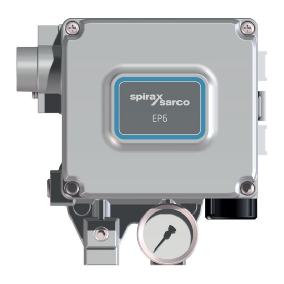
EP6
ATEX Electro-pneumatic Positioner
Installation and Maintenance Instructions
1. Safety information
2. General product information
3. Installation
4. Commissioning
5. Maintenance
6. Spare parts
7. Fault finding
8. Approvals
EP6 ATEX Electro-pneumatic Positioner
© Copyright 2021
1
IM-P703-04 CTLS Issue 3
Advertisement
Table of Contents

Subscribe to Our Youtube Channel
Related Manuals for Spirax Sarco EP6


Summary of Contents for Spirax Sarco EP6
- Page 1 CTLS Issue 3 ATEX Electro-pneumatic Positioner Installation and Maintenance Instructions 1. Safety information 2. General product information 3. Installation 4. Commissioning 5. Maintenance 6. Spare parts 7. Fault finding 8. Approvals EP6 ATEX Electro-pneumatic Positioner © Copyright 2021 IM-P703-04 CTLS Issue 3...
-
Page 2: Safety Information
(For NEPSI - according to the requirements of GB3836.1-2010 and GB3836.2-2010) and meet the requirements of the product explosion-proof mark, and the installation of the cable entry device Use must follow its instructions. EP6 ATEX Electro-pneumatic Positioner IM-P703-04 CTLS Issue 3... -
Page 3: Pressure Systems
Ensure that any pressure is isolated and safely vented to atmospheric pressure. Consider double isolation (double block and bleed) and the locking or labelling of closed valves. Do not assume that the system has depressurised even when the pressure gauge indicates zero. EP6 ATEX Electro-pneumatic Positioner IM-P703-04 CTLS Issue 3... -
Page 4: Protective Clothing
Customers and stockists are reminded that under EC Health, Safety and Environment Law, when returning products to Spirax Sarco they must provide information on any hazards and the precautions to be taken due to contamination residues or mechanical damage which may present a health, safety or environmental risk. -
Page 5: Product Return Procedure
Date of purchase Original order number iii. Serial number Please return all items to your local Spirax Sarco branch. Please ensure all items are suitably packed for transit (preferably in the original cartons). EP6 ATEX Electro-pneumatic Positioner IM-P703-04 CTLS Issue 3... -
Page 6: General Product Information
2. General product information 2.1 Introduction The EP6 is a 2 wire loop powered positioner requiring a 4-20 mA control signal, and is designed for use with linear and rotary pneumatic valve actuators. The positioner compares the electrical signal from a controller with the actual valve position and varies a pneumatic output signal to the actuator accordingly. - Page 7 ATEX / IECEx / KCs INMETRO CCC / NEPSI / ATEX / IECEx Fig. 1 EP6 ATEX Electro-pneumatic Positioner IM-P703-04 CTLS Issue 3...
-
Page 8: Operating Principle
(7) to stop the air coming into the chamber (10) through the SUPPLY. As a result, the actuator will stop operating and the positioner will return to its normal condition. EP6 ATEX Electro-pneumatic Positioner IM-P703-04 CTLS Issue 3... - Page 9 Nozzle Pilot 13 Feedback Lever Spool 14 Span lever (rotary motion) Supply chamber 15 Span adjuster 16 Span spring Seat Poppet 17 Zero adjuster Chamber Fig. 2 Linear positioner with an actuator EP6 ATEX Electro-pneumatic Positioner IM-P703-04 CTLS Issue 3...
- Page 10 (7) to stop the air coming into the chamber (10) through the SUPPLY. As a result, the actuator will stop operating and the positioner will return to its normal condition. EP6 ATEX Electro-pneumatic Positioner IM-P703-04 CTLS Issue 3...
- Page 11 11 Actuator spring Flapper 12 Actuator stem Nozzle 13 Cam Pilot 14 Span lever Spool 15 Span spring Supply chamber 16 Zero adjuster Seat Poppet Chamber Fig. 3 Rotary positioner with an actuator EP6 ATEX Electro-pneumatic Positioner IM-P703-04 CTLS Issue 3...
-
Page 12: Installation
-20 °C to +60 °C. The positioner enclosure is rated to IP66. Connection of air supply pressure (1.4 to 7 bar g) and control signal (4 - 20 mA) should be considered prior to choice of location. EP6 ATEX Electro-pneumatic Positioner IM-P703-04 CTLS Issue 3... -
Page 13: Tools For Installation
Fig. 5 Installation example Before proceeding with the installation, ensure following components are available. Positioner Mounting kit Air supply pipe and couplings Signal pipe and couplings to actuator Conduit gland connector EP6 ATEX Electro-pneumatic Positioner IM-P703-04 CTLS Issue 3... - Page 14 M8 cap head screw M8 hex head screw M8 spring washer M8 plain washer M8 nut Actuator coupling M6 cap head screw M5 nut Nut, spring washer and screw supplied with EP6/PP6 positioner EP6 ATEX Electro-pneumatic Positioner IM-P703-04 CTLS Issue 3...
- Page 15 Fit pin into relevant hole according to stroke 20, 30, 50 or 70 (observe markings on front face) Fig. 6 Exploded view of central mount assembly (PP6 positioner shown, for EP6 spacers are not required) EP6 ATEX Electro-pneumatic Positioner IM-P703-04 CTLS Issue 3...
- Page 16 M8 hex head screw M8 spring washer Actuator yoke or pillar M8 plain washer M8 nut M6 cap head screw UY1/UY3/UY4 M5 nut Nut, spring washer and screw supplied with EP6/PP6 positioner EP6 ATEX Electro-pneumatic Positioner IM-P703-04 CTLS Issue 3...
- Page 17 - see table on previous page and Figure xx for details Actuator coupling Discard when fitting UBC UBC only Fig. 7.2 Exploded view of side mount assembly (PP6 positioner shown) EP6 ATEX Electro-pneumatic Positioner IM-P703-04 CTLS Issue 3...
- Page 18 Fig. 8 Proper way to insert feedback pin between feedback lever and lever spring Fig. 9 Feedback lever and valve stem Stroke : 30 mm Stroke : 70 mm Fig. 10 Feedback lever and location of the feedback pin EP6 ATEX Electro-pneumatic Positioner IM-P703-04 CTLS Issue 3...
- Page 19 Components Positioner Rotary bracket set (2 pieces) Mounting kit Air supply pipe and couplings Signal pipe and couplings to actuator Conduit gland connector Fig. 12 Namur type EP6 ATEX Electro-pneumatic Positioner IM-P703-04 CTLS Issue 3...
- Page 20 Fig. 13 Positioner and mounting kit H = 50 H = 30 Ball valve actuator H = 20 Choose correct holes according to actuator stem height (H) See Figure 14 (both ends) EP6 ATEX Electro-pneumatic Positioner IM-P703-04 CTLS Issue 3...
- Page 21 Spirax actuator (BVA300) stem height is 30mm, assemble brackets as shown in Fig. 13 Please note, set rotation position of the actuator stem as shown in Fig. 13 when assembling, especially important for double acting actuators. EP6 ATEX Electro-pneumatic Positioner IM-P703-04 CTLS Issue 3...
- Page 22 For best performance, set the air supply pressure to about 0.5 bar g above the pressure required to fully travel the actuator. Check all connections for leaks. Please note however that the EP6 bleeds air in normal operation at a rate of approximately 2.5 LPM at 1.4 bar supply pressure.
- Page 23 When increasing input signal Supply 3.9.2.3 - Piping and cam direction setting for rotary single actuator Bearing Bearing Span Span When increasing When increasing input signal input signal Supply Supply Direct action Reverse action EP6 ATEX Electro-pneumatic Positioner IM-P703-04 CTLS Issue 3...
- Page 24 Note: For central mount reverse the Span lever When increasing input signal Supply 3.9.3.2 Piping and cam direction setting for rotary double actuator Bearing Span Direct action Supply Bearing Span Reverse action Supply EP6 ATEX Electro-pneumatic Positioner IM-P703-04 CTLS Issue 3...
- Page 25 3.9.4 Electrical connections The EP6 only requires a 4 - 20 mA signal. Unscrew junction box cover. Note: Ensure resistance from earth post to local earth (e.g. pipework) is less than 1 Ohm. Connection to the unit is through the conduit entry port, using a suitable ATEX cable gland (not supplied). See section 4.2.1.
- Page 26 Lock nut Connecting body Compounding charging box (flameproof type sealing fitting) Union cover Union coupling Conduit tube Insulated wire Fig. 15 Fig. 16 Pressure-proof packing union Flame proof type compound charge box EP6 ATEX Electro-pneumatic Positioner IM-P703-04 CTLS Issue 3...
- Page 27 Screw on junction box cover and fix with M3 set screw. Ground (M4) Black Ground (M4) Ground Spare bolt (M4) Controller (A0) (DCS/PLC sourcing output card) Fuse < 62mA Fig. 17 Connecting cables EP6 ATEX Electro-pneumatic Positioner IM-P703-04 CTLS Issue 3...
- Page 28 Adjust shaft Span lever Note: Views show side mount with lever Fig. 18 Span Installation (side = DA, central = RA) Lock screw Adjust shaft Roller M6 thread Fig. 19 Linear span assembly EP6 ATEX Electro-pneumatic Positioner IM-P703-04 CTLS Issue 3...
- Page 29 M6 Tap hole like the above Fig. 18 (RA) Span lever Feedback lever Adjust shaft Span Roller M6 top Note: Views show side mount with lever Fig. 20 Span Installation (side = RA, central = DA) EP6 ATEX Electro-pneumatic Positioner IM-P703-04 CTLS Issue 3...
- Page 30 Bearing Counterclockwise Fig. 21 Cam Installment (DA) Fig. 22 Cam Installment (RA) Clockwise M3 x 5L, truss head bolt Indicator M6 nut Nord lock washer Rotary main shaft Fig. 23 Parts (Standard) EP6 ATEX Electro-pneumatic Positioner IM-P703-04 CTLS Issue 3...
-
Page 31: Adjustment - Zero Point
Set input signal at 4mA (or 20mA) as the initial ampere and rotate the adjuster of zero unit handle upward or downward to adjust actuator’s zero point. Please refer to the below figure to increase or decrease the zero point. Fig. 24 Zero unit EP6 ATEX Electro-pneumatic Positioner IM-P703-04 CTLS Issue 3... -
Page 32: Adjustment - Span
Above two steps are required several times until both zero and span are properly set. After proper setting, tighten lock screw. Lock screw Lock screw Fig. 25 Linear span unit Fig. 26 Rotary span unit EP6 ATEX Electro-pneumatic Positioner IM-P703-04 CTLS Issue 3... -
Page 33: Adjustment - A/M Switch (Auto/Manual)
A f t e r u s i n g “ M a n u a l ” function, Auto/Manual switch should be returned to “Auto”. Auto manual switch Fig. 27 A/M switch adjustment Manual Auto EP6 ATEX Electro-pneumatic Positioner IM-P703-04 CTLS Issue 3... -
Page 34: Regular Maintenance
Make visual checks to ensure that the valve assembly is operating correctly. Wipe the unit with a damp cloth or antistatic products 6. Spare parts There are no spares for the positioner EP6 ATEX Electro-pneumatic Positioner IM-P703-04 CTLS Issue 3... -
Page 35: Fault Finding
Check for a gap or damages between the nozzle and the flapper. level and does not If damaged, please contact local Spirax Sarco office, quoting serial number.. come back down. Check if the positioner’s nozzle has been blocked. Also, check if the pressure... - Page 36 Certification No. : DNV 21.0017X Ambient temperature : -20 ~ 60°C (-4 ~ 140°F) 1) Rating : Ex dmb IIB T5 Certification No. : 21-KA2BO-0312X Ambient temperature : -20 ~ 70°C (-4 ~ 158°F) EP6 ATEX Electro-pneumatic Positioner IM-P703-04 CTLS Issue 3...
-
Page 37: Declaration Of Conformity
On behalf of: Spirax Sarco Ltd, (name, function): M Sadler Steam Business Development Engineering Product Integrity & Compliance Manager (place and date of issue): Cheltenham 2021-10-15 GNP234-EU-C/01 issue 3 (EN) Page 1/1 EP6 ATEX Electro-pneumatic Positioner IM-P703-04 CTLS Issue 3... - Page 38 EP6 ATEX Electro-pneumatic Positioner IM-P703-04 CTLS Issue 3...
- Page 39 EP6 ATEX Electro-pneumatic Positioner IM-P703-04 CTLS Issue 3...
- Page 40 EP6 ATEX Electro-pneumatic Positioner IM-P703-04 CTLS Issue 3...
Need help?
Do you have a question about the EP6 and is the answer not in the manual?
Questions and answers