Table of Contents
Advertisement
Quick Links
1484050/3
IM-P148-39
CMGT Issue 3
CAS14 and CAS14S
Austenitic Stainless Steel
Ball Float Air and Gas Traps - ½", ¾" and 1"
Installation and Maintenance Instructions
1. Safety information
2. General product information
3. Installation
4. Commissioning
5. Operation
6. Maintenance
7. Spare parts
© Copyright 2018
IM-P148-39 CMGT Issue 3
1
Printed in GB
Advertisement
Table of Contents

Related Manuals for Spirax Sarco CAS14


Summary of Contents for Spirax Sarco CAS14
- Page 1 1484050/3 IM-P148-39 CMGT Issue 3 CAS14 and CAS14S Austenitic Stainless Steel Ball Float Air and Gas Traps - ½", ¾" and 1" Installation and Maintenance Instructions 1. Safety information 2. General product information 3. Installation 4. Commissioning 5. Operation 6. Maintenance 7.
-
Page 2: Safety Information
DN25 - 50 DN15 - 20 CA16/CA16S DN25 DN15 - 20 CA44/CA44S DN25 - 50 DN15 - 20 CA46/CA46S DN25 - 50 CAS14/CAS14S DN15 - 25 BRair, BRoil and Airodyn Group 2 Group 2 Product Gases Liquids BRair BRoil Airodyn... -
Page 3: Pressure Systems
Determine the correct installation situation and direction of fluid flow. Spirax Sarco products are not intended to withstand external stresses that may be induced by any system to which they are fitted. It is the responsibility of the installer to consider these stresses and take adequate precautions to minimise them. -
Page 4: Protective Clothing
1.9 Tools and consumables Before starting work ensure that you have suitable tools and/or consumables available. Use only genuine Spirax Sarco replacement parts. 1.10 Protective clothing Consider whether you and/or others in the vicinity require any protective clothing to protect against the hazards of, for example, chemicals, high/low temperature, radiation, noise, falling objects, and dangers to eyes and face. -
Page 5: Returning Products
Customers and stockists are reminded that under EC Health, Safety and Environment Law, when returning products to Spirax Sarco they must provide information on any hazards and the precautions to be taken due to contamination residues or mechanical damage which may present a health, safety or environmental risk. -
Page 6: General Product Information
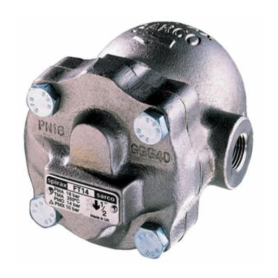
2. General product information 2.1 General description The CAS14 and CAS14S are austenitic stainless steel ball float gas/air drain traps. They provide efficient condensate drainage from compressed air and other gas systems, allowing the process to operate to its optimum potential. - Page 7 Fig. 1 CAS14 Screwed (vertical down) Valve spring Fig. 2 Section of the main valve assembly - DN25 (1") only IM-P148-39 CMGT Issue 3...
- Page 8 225 °C (437 °F) Minimum operating temperature -20 °C (-4 °F) Note: For lower operating temperatures consult Spirax Sarco. Designed for a maximum cold hydraulic test pressure of: 37.5 bar g (544 psi g) PMX - Maximum differential pressure The maximum differential pressure depends on the specific gravity of the liquid being drained.
-
Page 9: Installation
Ensure adequate space is left to remove the body from the cover for maintenance. Minimum withdrawal distance distance for the CAS14 ½" and ¾" is 135 mm (5.6") for the 1" it is 145 mm (5.8"). S6 separator Fig 3616 Fig. -
Page 10: Operation
4. Commissioning After installation or maintenance ensure that the system is fully functioning. Carry out tests on any alarms or protective devices. 5. Operation The compressed air ball float drain trap is a continuous discharge trap, removing condensate the instant it forms. - Page 11 6.2 How to fit the main valve assembly Undo the cover bolts (2). Place two screwdrivers between the body and cover on either side and lever off the body, keeping bolt holes aligned. Remove the pivot pin (14) and float assembly (8). Remove the two main valve assembly screws (7) and pivot frame (12).
-
Page 12: Spare Parts
Always order spares by using the description given in the column headed 'Available spares' and state the size and type of trap. Example: 1 - Maintenance kit for a Spirax Sarco ½" CAS14 austenitic stainless steel ball float air and gas trap. Fig. 5... - Page 13 Main valve assembly Note: Item 16 is required for the 1" size only Table 1 Recommended tightening torques Item Part (lbf ft) Cover bolt M10 x 30 20 - 25 (15 - 18) Main valve seat 17 A/F 50 - 55 (37 - 40) Main valve assembly screws Pozidrive...
- Page 14 IM-P148-39 CMGT Issue 3...
- Page 15 IM-P148-39 CMGT Issue 3...
- Page 16 IM-P148-39 CMGT Issue 3...
Need help?
Do you have a question about the CAS14 and is the answer not in the manual?
Questions and answers