Advertisement
Quick Links
Operating and Maintenance Instructions
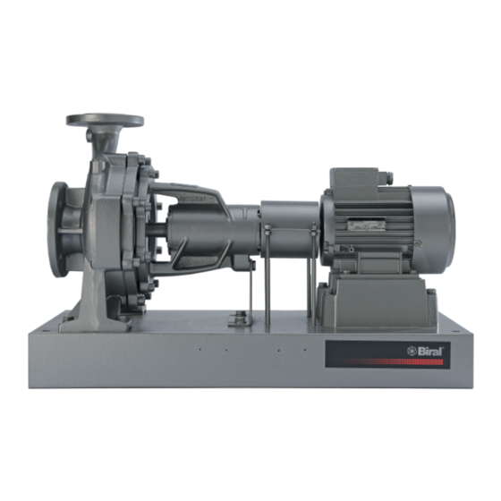
Volute-Casing Centrifugal Pumps
Series NT
Order No.:
Machine No.:
Operating data, dimensions and other additional information can be found in the order-specific part of the
documentation.
These Operating and Maintenance
Instructions contain information from
the pump manufacturer. They may need
to be supplemented by instructions of
the operator company for its personnel.
These instructions do not take account
of specific information relating to opera-
tion and maintenance of the process
plant into which the pump is integrated.
Such information can only be given by
the persons responsible for construc-
tion and planning of the plant (plant
manufacturer).
Such specific instructions relating to
operation and maintenance of the
process plant into which the pump is
integrated have priority over the
instructions of the pump manufac-
turer. The plant manufacturer must
on principle observe the limits of
use!
Refer to the operating instructions of
the plant manufacturer!
Pump Ident. No.:
Pump Type:
Contents
4. Description
Important note:
This operating manual is to be supplemented
by the order-related informations.
1
VM No.:
460.0002 GB
Edition:
Ident No.:
550 088
Retain
for future
use!
07.00
Advertisement

Subscribe to Our Youtube Channel
Related Manuals for Biral NT Series


Summary of Contents for Biral NT Series
-
Page 1: Table Of Contents
Operating and Maintenance Instructions VM No.: 460.0002 GB Edition: 07.00 Ident No.: 550 088 Volute–Casing Centrifugal Pumps Retain for future Series NT use! Order No.: Pump Ident. No.: Machine No.: Pump Type: Operating data, dimensions and other additional information can be found in the order–specific part of the documentation. -
Page 2: General
General Pump designation The exact designation can be found in the order–spe- cific documents (see data sheet). Proper use Information on proper use of the pumps is provided in the technical data sheet. The pumped liquid must not contain any abrasive con- stituents nor corrode the pump materials. -
Page 3: Safety
Safety These operating instructions contain basic safety Dangers in the event of non–compliance with instructions installation, operation safety instructions maintenance. It is therefore essential that they are read Failure to comply with the safety instructions may result by fitters and all specialist staff and customer personnel in danger to persons, and place the environment and prior to installation and start–up. -
Page 4: Transportation And Intermediate Storage
Safety instructions for maintenance, inspection Transportation and Intermediate Stor- and installation The operating company must ensure that all maintenance, inspection and installation tasks are Packaging performed by authorized and qualified specialist Attention must be paid to the figurative markings on the personnel who have thoroughly studied the operating packaging. - Page 5 Preservation / Storage of centrifugal pumps Note: The preservatives listed are to be regarded as a recommendation. Alternatively, technically equivalent 3.3.1 Preservation products from other manufacturers can be used. In the case of storage or prolonged standstill, the When handling preservatives, the safety hints con- pumps must be protected against corrosion.
- Page 6 Description / Principle design of the pump The pictorial presentation may not correspond with the pump supplied. The actual design will be stated in the specific order documents. Volute casing Impeller Bearing bracket Shaft Shaft seal Contact protection to EN 809 by coupling guard Earthing connection to EN 809 at the base plate...
-
Page 7: Installation/Mounting
Installation/Mounting Installation 5.2.3 Characteristics of a floor/concrete foundation For installation methods and locations, please see in- The foundation must be horizontal, flat and clean, and stallation drawing. be capable of bearing the full load upon it. Note: Concrete foundations must be executed with Other methods of installation are not permissible standard concrete of strength class B 25 as a minimum. - Page 8 Checking the coupling alignment Note: The permissible axial and radial deviation, measured on the front face of the coupling and the 5.4.1 Checking the coupling alignment in case of hori- coupling circumference respectively, may be max. zontal setup on base plate 0.1 mm, but as far as possible should be kept below A complete delivered pump aggregate has been care–...
- Page 9 Laying the pipelines 5.7.4 Cleaning pipelines prior to attachment Prior to assembly, all pipeline parts and valves must be 5.7.1 Nominal widths thoroughly cleaned. The nominal diameters of the pipelines need not No impurities must reach the pump from necessarily correspond to those of the inlet and outlet the pipeline system (e.g.
- Page 10 Safety and control devices 5.8.1 Manometers We recommend to provide suitable pressure gauges in the inlet and pressure pipelines, and in the pressurized auxiliary pipelines. 5.8.2 Safety devices in the inlet, delivery and auxiliary pipelines Safety devices in the form of stop valves must be installed in the pipelines, if not already provided, to allow the pipelines to be shut off and disconnected during maintenance and repair work.
-
Page 11: Start-Up/Shutdown
Start–up/Shutdown Preparations for (initial) start–up 6.2.4 Drive Switch on the motor. 6.1.1 Filling and bleeding the pump Refer to the operating instructions of the drive motor Prior to starting up, the pump and the suction and inlet manufacturer. pipeline must be filled with delivery fluid. During bleeding, the stop valves in the inlet and delivery 6.2.5 Minimum rate of flow... - Page 12 S Additional devices Switch off any additional devices (external flushing, external sealing, quench). In the case of double–acting mechan- ical seals, the pump and system must be depressurized before switching off the sealing pressure. It must be ensured that the pump does not run back- wards after switching off.
-
Page 13: Maintenance/Repair
Maintenance/Repair Maintenance 7.1.2.2 Shaft seal The shaft is sealed either by a stuffing box or S The instructions in Section 2, Safety, must be mechanical seal. observed in maintenance and repair work. S Stuffing box S Regular monitoring and maintenance of the pump Any increased leakages at the stuffing box in the and the drive motor are essential for optimum ser- initial operating hours are normally eliminated in the... - Page 14 Repair 7.2.1 Dismounting the centrifugal pump Before dismounting, the following work must be carried General out: The system operator is responsible for ensuring that in- S Electrical danger must be eliminated! The motor struction in safety is provided. The personnel must be made aware of all hazards that can arise in connection must be secured against being switched on.
- Page 15 7.2.2 Mounting the centrifugal pump Designation Producer Brand name Before remounting check all parts for wear to DIN 51825 and aging and, as necessary, replace with Agip Agip GR MU3 K3K–20 original replacement parts. Clean all parts before mounting. Always fit new ARAL Aralub HL3 K3K–20...
- Page 16 Following the mounting the centrifugal pump, the Replacement parts following operations are to be performed. The application guidelines in accordance with DIN 24 296 can be taken as a basis for spare parts stock hold- S Align coupling (please refer to Section 5.4 above). ing (see Section 7.3.2).
-
Page 17: Operating Faults, Causes And Remedial Action
Operating Faults, Causes and Remedial Action Faults with reference number for cause and remedial action The table below is intended as a guide to identifying faults and their possible causes. If faults occur which are not listed here, or which cannot be traced back to the listed causes, we recommend consulting the factory, or one of our branch offices or sales offices. - Page 18 Pump twisted. Check pipelines for twists in connections. Excessive axial thrust. Clean relief bore holes in impeller. – – Specified coupling half gap not complied with. Set coupling half gap as per installation diagram. Motor voltage incorrect. Use motor with correct voltage. Motor runs only to two phases.
-
Page 19: Associated Documentation
Associated Documentation Sectional drawing – Series NT Sizes at bearing bracket size 360, 470 and 530 Design of the bearing and impeller protection with bearing bracket size 530 Shaft seal: Stuffing box with internal sealing Design with intermediate ring Abbreviation: Stuffing box with Mechanical seal external sealing... - Page 20 Sectional drawing – Series NT Two–stage sizes at bearing bracket size 360 Mechanical seal unbalanced Mechanical seal unbalanced Casing cover design with pump size U3...D 2/40–250 and 2/50–250 Denomination Part No. Denomination Part No. Connections ––––––––––––––––––––––––––––––––––––– ––––––––––––––––––––––––––––––––––––– –––––––––––––––––––––––– Volute casing 102.01 Intermediate ring 509.01...
- Page 21 Sectional drawing – Series NT Sizes at bearing bracket size 228 Denomination Part No. –––––––––––––––––––––––––––––– Volute casing 102.01 Casing cover 161.01 Casing cover 161.03 Casing cover 161.05 Casing cover 161.06 Casing cover 161.08 Shaft 210.01 Shaft 210.04 Impeller 230.01 Groove ball bearing 321.01 Groove ball bearing 321.02...
- Page 22 Sectional drawing – Series NT Sizes at bearing bracket size 585 Denomination Part No. –––––––––––––––––––––––––––––– Volute casing 102.01 Casing cover 161.01 Casing cover 161.03 Casing cover 161.05 Casing cover 161.08 Supporting foot 183.01 Shaft 210.01 Impeller 230.01 Groove ball bearing 321.03 Groove ball bearing 321.04...
- Page 23 Sectional drawing – Series NT Denomination Part No. Sizes at bearing bracket size 700 –––––––––––––––––––––––––––––– Volute casing 102.01 Casing cover 161.01 Suction cover 162.01 Pump stool 181.01 Foot 182.01 Supporting foot 183.10 Shaft 210.01 Impeller 230.01 Groove ball bearing 321.04 Radial roller bearing 322.01 Bearing bracket...
- Page 24 These operating instructions are supplemented by the following documents: Acceptance of order Data sheet Installation drawing Sectional drawing Part list Subject to technical changes. Biral AG Südstrasse 10 CH 3110 Münsingen/Switzerland Telefon 031 7209000 Telefax 031 7215644 VM 460.0002 GB/07.00 – Ident–Nr. 550 088...
- Page 25 - DIN EN 292 T.2 - DIN EN 292 T.2 Dichiarazione di conformità Declaration of conformity Noi, ditta Biral, dichiariamo sotto la nostra We, the Biral Company, taking sole responsibility, responsabilità assoluta che i prodotti declare that the products Pompe centrifughe normalizzate NT/NB...
Need help?
Do you have a question about the NT Series and is the answer not in the manual?
Questions and answers