
Related Manuals for UNI-T UT70A


Summary of Contents for UNI-T UT70A
-
Page 1: Table Of Contents
Model UT70A: OPERATING MANUAL TABLE OF CONTENTS TITLE PAGE HIGHLIGHTS NOTES FOR SAFE USAGE FIGURATION AND ACCESSORIES ELECTRIC SYMBOL GENERAL INFORMATION SPECIFICATIONS 1.DC Voltage (DCV) 2.AC Voltage (ACV) 3.DC Current (DCA) 4.AC Current (ACA) 5.Resistance 6.Capacitance 7. Inductance 8.Auto range frequency test 9.Transistor hFE measurement... - Page 2 Model UT70A: OPERATING MANUAL TABLE OF CONTENTS TITLE PAGE 11. Transistor Parameter Measurement (hFE) 12. Diode (or PN node of transistor) Measurement( ) 13. Continuity Buzzer Test 14. TTL LOGIC Test MAINTENANCE FUSE AND BATTERY replacement Accessories...
-
Page 3: Highlights
Model UT70A: OPERATING MANUAL Operating Manual of UT70A Multimeter HIGHLIGHTS UT70A Multimeter is a hand-held digital multimeter with advanced design, multiple functions, novel figuration, large display screen and reliable performance. This meter is fully capable to measure voltage and current both AC... - Page 4 Model UT70A: OPERATING MANUAL 5) Set the Range Selector to a proper position. 6) The measured value shall not exceed the maximum range of each measurement to protect the meter from damage and electric shock to user. 7) Range Selector shall not be switched during measurement to avoid damage to the meter.
-
Page 5: Figuration And Accessories
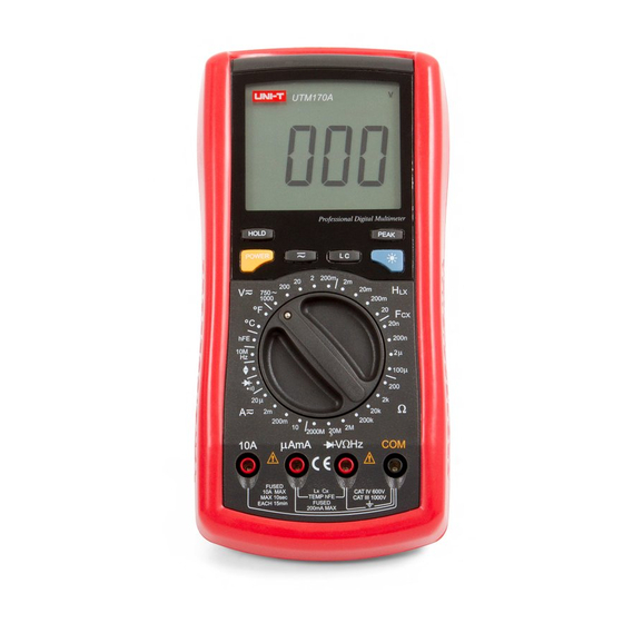
Model UT70A: OPERATING MANUAL FIGURATION AND ACCESSORIES 1) The Meter Structure(see figure1) 1. Front case 2. Functional buttons 3. Function/Range selector 4. Input terminal 5. LCD window... - Page 6 Model UT70A: OPERATING MANUAL 2) Input Terminal of UT70A Input Terminal Description For short Input terminal for current "A" Terminal 0.2A-10A. "mA"Terminal Input terminal for voltage, "V/ " resistance, frequency, Terminal diode, continuity, TTL LOGIC. Common terminal for current, "COM"Terminal...
-
Page 7: Electric Symbol
Model UT70A: OPERATING MANUAL ELECTRIC SYMBOL AC (Alternating Current) DC (Direct Current) AC or DC Grounding Double Insulated Deficiency of Built-In Battery Continuity buzzer Diode Fuse Warning. Refer to the Operating Manual Conforms to Standards of European Union... -
Page 8: General Information
Model UT70A: OPERATING MANUAL GENERAL INFORMATION l Maximum voltage between any terminal and the ground: 1000V l 3 1/2 digits large screen displaying size: 53 mm x 62 mm, Max reading 1999. l Simultaneous display function and unit icon. l Automatic power off after 15 non-operated minutes l Automatic polarity, over range "OL"... -
Page 10: Specifications
Model UT70A: OPERATING MANUAL SPECIFICATIONS(2) 3.DC Current (DCA) Range Resolution Accuracy Input protection (0.8%+1) F. 0.5A/250V (1.5%+1) F. 10A/250V (2%+5) Remarks: 4. AC Current (ACA) Range Resolution Accuracy Input protection (1%+3) F. 0.5A/250V (1.8%+3) F. 10A/250V (3%+7) 5. Resistance Range... - Page 13 Model UT70A: OPERATING MANUAL SPECIFICATIONS(5) In Fahrenheit ( Range Resolution Accuracy Input protection (3%+4) F - 32 F - 752 (1%+4) 250 Vrms 1832 2.5% F - 1832...
-
Page 14: Operation Instruction
Model UT70A: OPERATING MANUAL OPERATION INSTRUCTION(1) -
Page 15: Introduction Of Functional Buttons
Model UT70A: OPERATING MANUAL OPERATION INSTRUCTION(2) 1. Introduction of functional buttons 2. DC Voltage Measurement (DCV)(see figure2) - Page 16 Model UT70A: OPERATING MANUAL OPERATION INSTRUCTION(3) WARNING: Not to measure a Voltage higher than 1000V. A reading might be available but it may result in damage to the internal circuit.
-
Page 17: Ac Voltage Measurement (Acv)
Model UT70A: OPERATING MANUAL OPERATION INSTRUCTION(4) 3.AC Voltage Measurement (ACV)(see figure3) WARNING: Not to measure a Voltage higher than 750V. A reading might be available but it may result in damage to the internal circuit. -
Page 18: Current Measurement (Dca)
Model UT70A: OPERATING MANUAL OPERATION INSTRUCTION(5) 4. Current Measurement (DCA)(see figure4) WARNING: Turn off the circuit power to be tested before linking the meter with the circuit. Measurement of Voltage in this mode is forbidden. -
Page 19: Ac Current Measurement (Aca)
Model UT70A: OPERATING MANUAL OPERATION INSTRUCTION(6) 5.AC Current Measurement (ACA)(see figure5) WARNING: Turn off the circuit power to be tested before linking the meter with the circuit. Measurement of Voltage in this mode is forbidden. -
Page 20: Resistance Measurement
Model UT70A: OPERATING MANUAL OPERATION INSTRUCTION(7) 6. Resistance Measurement ( )(see figure6) -
Page 21: Inductance Measurement (L)
Model UT70A: OPERATING MANUAL OPERATION INSTRUCTION(8) WARNING: It is not allowed to make a measurement in a live return circuit. Return circuit power shall be cut off and capacitor/s in return circuit shall be discharged (large capacitance value in particular) before measuring. -
Page 22: Capacitance Measurement (C)
Model UT70A: OPERATING MANUAL OPERATION INSTRUCTION(9) WARNING: Inductance test shall be stay away from any strong magnetic field to ensure an accurate measurement. 8. Capacitance Measurement (C)(see figure8) -
Page 23: Frequency Measurement (10Mhz)
Model UT70A: OPERATING MANUAL OPERATION INSTRUCTION(10) WARNING: It is not allowed to make measurement of capacitance on live circuit. The capacitor to be tested shall be discharged by short-circuiting before test. 9. Frequency Measurement (10MHz)(see figure9) -
Page 24: Temperature Measurement
Model UT70A: OPERATING MANUAL OPERATION INSTRUCTION(11) 10.Temperature Measurement ( C or F)(see figure10) 11.Transistor Parameter Measurement (hFE) -
Page 25: Diode (Or Pn Node Of Transistor) Measurement( )
Model UT70A: OPERATING MANUAL OPERATION INSTRUCTION(12) 12. Diode (or PN node of transistor) Measurement( ) WARNING: No voltage signal shall be introduced into measurement. 13. Continuity Buzzer Test WARNING: Continuity buzzer test cannot be made in live return circuit. Power in live return circuit shall be cut off and capacitor (large capacitance value in particular) shall be discharged before test. -
Page 26: Ttl Logic Test
Model UT70A: OPERATING MANUAL OPERATION INSTRUCTION(13) 14.TTL LOGIC Test... -
Page 27: Maintenance
Model UT70A: OPERATING MANUAL MAINTENANCE WARNING! This digital multimeter is a precise electronic instrument and no alternation shall be made to its circuit. Furthermore, the following points shall be attended: 1) not connect it to any DC voltage higher than 1000 V or AC voltage higher than 750 V. -
Page 28: Fuse And Battery Replacement
Model UT70A: OPERATING MANUAL FUSE AND BATTERY replacement 1) Turn OFF the Power, and remove the test leads from terminals 2) Remove all rubber foot and screws from the back case. 3) Separate the back case from the front case. - Page 29 Model UT70A: OPERATING MANUAL...
- Page 30 Model UT70A: OPERATING MANUAL Copyright 2001 Uni-Trend International Limited. All rights reserved. Manufacturer: UNI-TREND TECHNOLOGY(DONG GUAN)LIMITED Address: Dong Fang Da Dao, Bei Shan Dong Fang Industrial Development District, Hu Men Town, Dong Guan City, Guang Dong Province, China Headquarters: Uni-Trend International Limited...
Need help?
Do you have a question about the UT70A and is the answer not in the manual?
Questions and answers