
Related Manuals for Lenze EPM-T9 Series


Summary of Contents for Lenze EPM-T9 Series
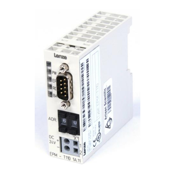
- Page 1 Show/Hide Bookmarks EDSPM-TXXX !Qz& System Manual epm-t007 Global Drive I/O system IP20 EPM-T110, EPM-T2xx, EPM-T3xx, EPM-T4xx, EPM-T83x, EPM-T9xx...
-
Page 2: Table Of Contents
Show/Hide Bookmarks Preface Contents Preface Contents The I/O system IP20 ............1.2-1 How to use this System Manual . -
Page 3: The I/O System Ip20
The increasing number of peripherals has increased the amount of wiring required. This is where distributed I/O systems bring order to the chaos. Lenze has developed two new product concepts with IP20 protection which are suitable for both basic digital applications and more complex automation tasks. -
Page 4: How To Use This System Manual
...) are included in the corresponding Catalogues, Operating Instructions, and Manuals. The required documentation can be ordered at your Lenze sales partner or downloaded as PDF file from the internet. The System Manual is designed as a loose-leaf collection so that we are able to Paper or PDF inform you quickly and specifically about news and changes. -
Page 5: Products To Which The System Manual Applies
Show/Hide Bookmarks Preface How to use this System Manual 1.3.2 Products to which the System Manual applies 1.3.2 Products to which the System Manual applies EPM-T XX XxDC24V XX XxDC24V XX XxDC24V XX XxDC24V XX XxDC24V XX XxDC24V XX XxDC24V XX XxDC24V XX XxDC24V XX XxDC24V... -
Page 6: Legal Regulations
Manual. The specifications, processes, and circuitry described in this System Manual are for guidance only and must be adapted to your own specific application. Lenze does not take responsibility for the suitability of the process and circuit proposals. - Page 7 Show/Hide Bookmarks Guide Contents Guide Contents Glossary ..............2.2-1 2.2.1 Terminology and abbreviations used...
-
Page 8: Guide
Show/Hide Bookmarks Guide Glossary Terminology and abbreviations used 2.2.1 Glossary 2.2.1 Terminology and abbreviations used Analog input data Analog input and output data Any frequency inverter, servo inverter or DC speed controller Controller Analog output data Control Area Network Communication profile to DS 301, published by CiA (CAN in CANopen Automation) Communauté... -
Page 9: Edspm-Txxx-3.0
Show/Hide Bookmarks Guide Glossary 2.2.1 Terminology and abbreviations used Parameter data output object SDO-Tx Synchronous serial interface Lenze system bus System bus (CAN) Period Underwriters Laboratories Verband deutscher Elektrotechniker Cross-reference to a chapter with the corresponding page number 2.2-2 EDSPM-TXXX-3.0-04/2004... -
Page 10: Total Index
Show/Hide Bookmarks Guide Total index Total index 16xdig. I/O compact (single-wire conductor) 2/4xcounter - Connection, 5.13-2 - Description, 6.3-1 - Counter mode - Features, 6.3-1 2 × 32 bit-counter with GATE and set/reset, 12.4-35 - Overview, 6.3-1 2 × 32-bit counter with GATE and RES edge-triggered, - Status display, 6.3-5 12.4-45 2 ×... - Page 11 Show/Hide Bookmarks Guide Total index 4xanalog input /output 8xdigital output 1A - Connection, 5.5-2 - Connection, 5.12-2 - Description, 5.5-1 - Status display, 5.12-2 - Features, 5.5-1 - Technical data, 5.12-3 - Overview, 5.5-1 - Terminal assignment, 5.12-2 - Status display, 5.5-2 - Technical data, 5.5-2 4xanalog output - Terminal assignment, 5.5-2...
- Page 12 Show/Hide Bookmarks Guide Total index CANopen Description - 16xdig. I/O compact (single-wire conductor), 6.3-1 - Connecting, 5.2-2, 6.2-2, 6.3-2, 6.4-2, 6.5-2 - 16xdig. I/O compact (three-wire conductor), 6.4-1 - Connection to the module, Pin assignment, 5.2-2, - 16xdigital input, 5.4-1 6.2-2, 6.3-2, 6.4-2, 6.5-2 - 16xdigital output 1A, 5.6-1 - Networking via, 10.1-1...
- Page 13 Show/Hide Bookmarks Guide Total index Enclosure, 4.2-1 Input data - Transfer at 1xcounter/16xdigital input, 12.6-2 Error Response, 9.5-2, 10.5-2 - Transmitting - SSI interface, 12.5-3 - transmitting with 2/4xcounter, 12.4-4 - Transmitting with analog modules, 12.3-7 Installation Fault indications - CANopen, 8.5-1 - at 8xdig.
- Page 14 Show/Hide Bookmarks Guide Total index Network status, 9.3-1, 10.3-1 Parameter setting, 12.1-1 - 1xcounter/16xdigital input Display of the parameter data, 12.6-1 Networking Input data transfer, 12.6-2 - CANopen, 10.1-1 Meaning of the parameter data, 12.6-1 Output data transfer, 12.6-2 - via system bus (CAN), 9.1-1 - 2/4xcounter Display of the parameter data, 12.4-1 Node address...
- Page 15 Show/Hide Bookmarks Guide Total index SSI interface - Connection, 5.14-2 Technical data, 4.1-1 - Description, 5.14-1 - 16xdig. I/O compact (single-wire conductor), 6.3-7 - 16xdig. I/O compact (three-wire conductor), 6.4-7 - Features, 5.14-1 - 16xdigital input, 5.4-2 - Overview, 5.14-1 - 16xdigital output 1A, 5.6-2 - Parameter setting, 12.5-1 - 1xcounter/16xdigital input, 5.15-3...
- Page 16 Show/Hide Bookmarks Guide Total index Troubleshooting and fault elimination, 13.1-1 Warranty, 1.4-1 User data, 9.4-1, 10.4-1 Write Request, 9.5-2, 10.5-2 Write Response, 9.5-2, 10.5-2 Vibration resistance, 4.2-1 Writing parameters, 9.5-4, 10.5-4 2.3-7 EDSPM-TXXX-3.0-04/2004...
-
Page 17: List Of Illustrations
Show/Hide Bookmarks Guide List of illustrations List of illustrations Fig. 5.2-1 Overview of CAN gateway ..........5.2-1 Fig. - Page 18 Show/Hide Bookmarks Guide List of illustrations Fig. 6.2-3 Coding switch a CAN gateway ......... . 6.2-2 Fig.
- Page 19 Show/Hide Bookmarks Guide List of illustrations Fig. 9.8-1 Heartbeat Protocol ..........9.8-1 Fig.
- Page 20 Show/Hide Bookmarks Guide List of illustrations Fig. 12.4-22 Signal characteristic of 2/4xcounter in mode 8 considering as example the counters 0.1 and 0.2 ......12.4-15 Fig.
- Page 21 Show/Hide Bookmarks Guide List of illustrations Fig. 12.4-57 Signal characteristic of 2/4xcounter in the mode 28 (downcounter) ....12.4-42 Fig. 12.4-58 Signal characteristic of 2/4xcounter in the mode 29 (upcounter) .
- Page 22 Show/Hide Bookmarks Guide List of illustrations Fig. 12.6-7 Counter access of 1xcounter/16xdigital input in the mode 1 ....12.6-7 Fig. 12.6-8 Signal characteristic of 1xcounter/16xdigital input in the mode 1 (upcounter) .
- Page 23 Show/Hide Bookmarks Safety instructions Contents Safety instructions Contents Layout of the safety instructions ..........3.2-1 3.1-1 EDSPM-TXXX-3.0-04/2004...
-
Page 24: Edspm-Txxx-3.0
Show/Hide Bookmarks Safety instructions Layout of the safety instructions Layout of the safety instructions All safety information given in these Instructions have the same structure: Pictograph (indicates the type of danger) Signal word! (indicates the severity of danger) Note (describes the danger and informs the reader how to avoid danger) Pictograph Signal word... - Page 25 Show/Hide Bookmarks Technical data Contents Technical data Contents General data/operating conditions ..........4.2-1 4.1-1 EDSPM-TXXX-3.0-04/2004...
- Page 26 Show/Hide Bookmarks Technical data General data/operating conditions General data/operating conditions Standards and application Conformity Low-Voltage Directive (73/23/EWG) conditions Approvals UL508 Industrial Control Equipment Vibration resistance 1G/12G, in accordance with IEC 60068-2-6 / 60068-2-27 Climatic conditions RH1 in accordance with EN 61131-2 (without moisture condensation, relative humidity 50 % ...
- Page 27 Show/Hide Bookmarks The modular system Contents The modular system Contents CAN gateway ............5.2-1 8×digital input .
-
Page 28: Can Gateway
Show/Hide Bookmarks The modular system CAN gateway CAN gateway The CAN gateway is the interface between the process level and the master bus Description system. The control signals at the process level are transmitted by the electronic modules. These modules are connected with the CAN gateway via the backplane bus (EPM-T9XX). - Page 29 Show/Hide Bookmarks The modular system CAN gateway Connecting system bus (CAN)/CANopen epm-t023 Fig. 5.2-2 Connection to the system bus (CAN)/CANopen with 9-pole Sub-D plug Pin Assignment Not assigned CAN-LOW CAN-GND Not assigned Not assigned Not assigned CAN-HIGH Not assigned Not assigned Use the coding switch to set the baud rate.
- Page 30 Coding switch value [kbit/s] 1000 Bold print = Lenze setting 1. Switch off the voltage supply of the module. 2. Use the coding switch to set the required baud rate. – Select ”9x”, when using the ”system bus (CAN)” protocol (x = value for the required baud rate) –...
- Page 31 Show/Hide Bookmarks The modular system CAN gateway Status display Status Meaning PW (yellow) Module supply voltage on ER (red) Incorrect data transmission on the backplane bus. Signals error-free data transmission on the backplane bus. RD (green) RD (green) See table below BA (yellow) See table below PW (yellow)
-
Page 32: Dimensions, 7
Show/Hide Bookmarks The modular system CAN gateway Type CAN gateway Technical data Voltage supply DC 24 V / max. 700 mA (DC 20.4 ... 28.8 V) Max. current consumption of electronic modules Connectable cable cross-section ≤ 2.5 mm (≥ AWG 14) Communication •... -
Page 33: 8×Digital Input
Show/Hide Bookmarks The modular system 8×digital input 8×digital input The module 8×digital input detects the binary control signals of the process level Description and transfers them to the master bus system. 8 digital inputs Features Suitable for switches and proximity switches LED displays the states of the digital inputs Overview epm-t015... - Page 34 Show/Hide Bookmarks The modular system 8×digital input Status display and terminal assignment DI 8xDC24V – EPM – T210 1A DC 24 V (DC 18 … 28.8 V) epm-t025 epm-t026 Fig. 5.3-2 Front view and connection of 8×digital input Status display .0 ..7; LED (green) is Terminal strip assignment details lit when a HIGH level is recognised HIGH l...
-
Page 35: 16×Digital Input
Show/Hide Bookmarks The modular system 16×digital input 16×digital input The module 16×digital input detects the binary control signals of the process level Description and transfers them to the master bus system. Note! The chapter ”Parameter setting” describes how to parameterise the module. - Page 36 Show/Hide Bookmarks The modular system 16×digital input Status display and terminal DI 16xDC24V assignment – EPM – T211 DC 24 V (DC 18 … 28.8 V) epm-t125 epm-t121 Fig. 5.4-2 Front view and connection of 16×digital input 2 × status display .0 ..7; LED Terminal strip assignment details (green) is lit when a HIGH level is ) i lit...
-
Page 37: 8×Digital Output 1A
Show/Hide Bookmarks The modular system 8×digital output 1A 8×digital output 1A The module 8×digital output 1A detects the binary control signals from the master Description bus system and transports them to the process level via the outputs. The digital outputs are supplied via an external voltage supply (DC 24 V). Note! The chapter ”Parameter setting”... - Page 38 Show/Hide Bookmarks The modular system 8×digital output 1A Status display and terminal assignment DO 8xDC24V 1A – EPM – T220 1A DC 24 V (DC 18 … 35 V) epm-t017 epm-t016 Fig. 5.5-2 Front view and connection of 8×digital output 1A Status display L+;...
-
Page 39: 16×Digital Output 1A
Show/Hide Bookmarks The modular system 16×digital output 1A 16×digital output 1A The module 16×digital output 1A detects the binary control signals from the Description master bus system and transports them to the process level via the outputs. The digital outputs are supplied via an external voltage source (DC 24 V). Note! The chapter ”Parameter setting”... - Page 40 Show/Hide Bookmarks The modular system 16×digital output 1A Status display and terminal DO 16xDC24V 1A assignment – EPM – T223 1A DC 24 V (DC 18 … 35 V) epm-t126 epm-t122 Fig. 5.6-2 Front view and connection of 16×digital output 1A Status display L+;...
-
Page 41: 8×Digital Output 2A
Show/Hide Bookmarks The modular system 8×digital output 2A 8×digital output 2A The module 8×digital output 2A detects the binary control signals from the master Description bus system and transports them to the process level via the outputs. The digital outputs are supplied via an external voltage source (DC 24 V). Note! The chapter ”Parameter setting”... - Page 42 Show/Hide Bookmarks The modular system 8×digital output 2A Status display and terminal assignment DO 8xDC24V 1A – EPM – T220 1A DC 24 V (DC 18 … 35 V) epm-t017 epm-t016 Fig. 5.7-2 Front view and connection of 8×digital output 2A Status display L+;...
-
Page 43: 4×Relay
Show/Hide Bookmarks The modular system 4×relay 4×relay The module 4×relay detects the binary control signals from the master bus system Description and transports them to the process level via the outputs. The module has four relays with a switch each (NO contact). Note! The chapter ”Parameter setting”... - Page 44 Show/Hide Bookmarks The modular system 4×relay Status display and terminal +5 V assignment DO 4xRELAIS ‚ EPM – T222 1A epm-t020 epm-t021 Fig. 5.8-2 Front view and connection of 4×relay Status display; LED (green) is lit when Terminal strip assignment a relay output is triggered a relay out ut is triggered details...
-
Page 45: Xrelay, 5
Show/Hide Bookmarks The modular system 4×relay Technical data Maximum relay contact switching capacity Relay contact life I [A] ‚ ƒ „ … U [V] 20 30 50 200 300 3 4 5 epm-t018 epm-t019 Fig. 5.8-3 Diagrams for the module 4×relay Contact current Number of switching cycles ×... -
Page 46: 8×Digital Input / Output
Show/Hide Bookmarks The modular system 8×digital input / output 8×digital input / output The channels of the module 8×digital input / output can be used either as digital Description inputs or outputs. The digital inputs or outputs are supplied via an external voltage source. - Page 47 Show/Hide Bookmarks The modular system 8×digital input / output Status display and terminal assignment DIO 8xDC24V 1A – DC 24 V (DC +18 … +35 V) EPM – T230 1A epm-t027 epm-t028 Fig. 5.9-2 Front view and connection of 8×digital input / output Status display L+;...
- Page 48 Show/Hide Bookmarks The modular system 8×digital input / output Type 8×digital input / output Technical data Voltage supply DC 5 V / 50 mA (via backplane bus) Connectable cable cross-section ≤ 2.5 mm (≥ AWG 14) Digital inputs / outputs Number 8, can be optionally parameterised as inputs or outputs Electrical isolation from backplane bus...
-
Page 49: 4×Analog Input
Show/Hide Bookmarks The modular system 4×analog input 5.10 5.10 4×analog input The module 4×analog input has four analog inputs which can be parameterised Description individually. The module assigns a total of eight bytes of input data in the process image (two bytes per input). The analog inputs are isolated with regard to the backplane bus. - Page 50 Show/Hide Bookmarks The modular system 5.10 4×analog input Status display and terminal assignment AI 4x16BIT EPM – T310 1A 10 epm-t029 Fig. 5.10-2 Front view 4×analog input Status display LED (red) is lit in case of a wire breakage in the measuring range of 4 ... 20 mA LED (red) is blinking at an input current of >40 mA F0 Analog input E.0 F1 Analog input E.1...
- Page 51 Show/Hide Bookmarks The modular system 4×analog input 5.10 Connection Two-wire connection Four-wire connection µP µP epm-t036 epm-t033 Fig. 5.10-3 Sensor connection Analog input E.0 Analog input E.2 Connection to backplane bus HF shield termination through large-surface connection to PE Sensor: Voltage or current source Thermal element Resistor...
- Page 52 Show/Hide Bookmarks The modular system 5.10 4×analog input Type 4×analog input Technical data Voltage supply DC 5 V / 240 mA (via backplane bus) Connectable cable cross-section ≤ 2.5 mm (≥ AWG 14) Analog inputs Number Input area Voltage -10 ... +10 V -4 ...
- Page 53 Show/Hide Bookmarks The modular system 4×analog output 5.11 5.11 4×analog output The module 4×analog output has four analog outputs which can be parameterised Description individually. The analog outputs are isolated with regard to the backplane bus. Note! The chapter ”Parameter setting” describes how to parameterise the module.
- Page 54 Show/Hide Bookmarks The modular system 5.11 4×analog output Status display and terminal assignment AO 4x12BIT DC 24 V µP (DC 19.2 … 28.8 V) – EPM – T320 1A 10 epm-t030 epm-t037 Fig. 5.11-2 Front view and connection of 4×analog output Status display L+;...
- Page 55 Show/Hide Bookmarks The modular system 4×analog output 5.11 Type 4×analog output Technical data Voltage supply DC 5 V / 20 mA (via backplane bus) External voltage supply DC 24 V / 200 mA (DC 19.2 ... 28.8 V) Connectable cable cross-section ≤...
- Page 56 Show/Hide Bookmarks The modular system 4×analog input / output 5.12 5.12 4×analog input / output The module 4×analog input / output has two analog inputs and two analog outputs Description which can be parameterised individually. The analog inputs and outputs are isolated from the backplane bus and the voltage supply.
- Page 57 Show/Hide Bookmarks The modular system 5.12 4×analog input / output Status display and terminal assignment AI/AO 2/2x12BIT DC 24 V µP (DC 20.4 … 28.8 V) – EPM – T330 1A. 10 epm-t127 epm-t123 Fig. 5.12-2 Front view and connection of 4×analog input / output Status display L+;...
- Page 58 Show/Hide Bookmarks The modular system 4×analog input / output 5.12 Type Technical data 4×analog input / output Voltage supply DC 5 V / 100 mA (via backplane bus) External voltage supply DC 24 V / 110 mA (DC 20.4 ... 28.8 V) Short-circuit current 30 mA Connectable cable cross-section...
-
Page 59: 2/4×Counter
Show/Hide Bookmarks The modular system 2/4×counter 5.13 5.13 2/4×counter The module 2/4×counter detects the pulses of the connected encoders and Description processes these pulses according to the mode selected. The module has two 32-bit counters or four 16-bit counters. Each 32-bit counter has a digital output which can be triggered depending on the mode. - Page 60 Show/Hide Bookmarks The modular system 5.13 2/4×counter Status display and terminal assignment 2 Counter 2 DO ‚ OUT0 DC 24 V (DC 18 … 30 V) – ‚ OUT1 EPM – T410 1A 10 epm-t038 epm-t039 Fig.
- Page 61 Show/Hide Bookmarks The modular system 2/4×counter 5.13 Mode of Function Function OUT0 OUT0 OUT1 OUT1 Auto Auto Compare Compare Reload Reload Load Load [dec] 2 counters 2 × 32-bit counters GATE GATE • • – (counting direction up) • • 2 ×...
- Page 62 Show/Hide Bookmarks The modular system 5.13 2/4×counter Mode of Function Function OUT0 OUT0 OUT1 OUT1 Auto Auto Compare Compare Reload Reload Load Load [dec] 2 counters 32-bit counter • • – – G/RES G/RES Encoder 1 edge • • – –...
- Page 63 Show/Hide Bookmarks The modular system 2/4×counter 5.13 Type Technical data 2/4×counter Order designation EPM-T410 Voltage supply DC 5 V / 80 mA (via backplane bus) Connectable cable cross-section ≤ 2.5 mm (≥ AWG 14) Counters Number 2 × 32-bit counter or 4 × 16-bit counter Operating modes 36 modes Counting frequency...
-
Page 64: Ssi Interface
Show/Hide Bookmarks The modular system SSI interface 5.14 5.14 SSI interface Description An SSI interface (Synchronous Serial Interface) is a synchronously pulsed, serial interface. SSI interface module permits the connection of absolutely coded sensors with SSI interfaces. The module converts the serial information of the sensor into a parallel information and makes it available to the control. - Page 65 Show/Hide Bookmarks The modular system 5.14 SSI interface Status display and terminal assignment – µP DC 24 V (DC 18 … 28.8 V) – EPM – T411 1A. 10 epm-t124 epm-t130 Fig. 5.14-2 Front view and connection of SSI interface Status display L+;...
- Page 66 Show/Hide Bookmarks The modular system SSI interface 5.14 Type SSI interface Technical data Voltage supply DC 5 V / 200 mA (via backplane bus) External voltage supply DC 24 V / 50 mA mA (DC 18 ... 28.8 V) Connectable cable cross-section ≤...
-
Page 67: 1×Counter/16×Digital Input
Show/Hide Bookmarks The modular system 1×counter/16×digital input 5.15 5.15 1×counter/16×digital input The module 1×counter/16×digital input detects the binary control signals of the Description process level and transfers them to the master bus system. In addition, a counter can be triggered via the first two inputs. Note! The chapter ”Parameter setting”... - Page 68 Show/Hide Bookmarks The modular system 5.15 1×counter/16×digital input Status display and terminal 1C/DI 16xDC24V assignment ‚ ƒ EPM – T430 1A – DC 24 V (DC 18 … 28.8 V) epm-t128 epm-t131 Fig. 5.15-2 Front view and connection 1×counter/16×digital input 2 ×...
- Page 69 Show/Hide Bookmarks The modular system 1×counter/16×digital input 5.15 Type 1×counter/16×digital input Technical data Voltage supply DC 5 V / 100 mA (via backplane bus) Connectable cable cross-section ≤ 1.5 mm (≥ AWG 16) Digital inputs Rated input voltage DC 24 V (DC 18 ... 28.8 V) Number of inputs Level LOW: DC 0 ...
-
Page 70: Terminal Module
Show/Hide Bookmarks The modular system Terminal module 5.16 5.16 Terminal module The terminal module offers two terminal strips with 11 terminals each. All terminals Description of a terminal strip are connected with each other. The terminal strips are potential-free. Sensors which must be supplied with external voltage, for instance, can be wired with the help of the terminal module with a minimum of effort. -
Page 71: Terminal Module, 5
Show/Hide Bookmarks The modular system 5.16 Terminal module Type Terminal module Technical data Terminals Terminal strips 2 spring-mounted clamps, not plug-in Terminals per strip Max. current capacity per terminal strip Connectable cable cross-section ≤ 2.5 mm (≥ AWG 14) Dimensions Width 25.4 mm Height... - Page 72 Show/Hide Bookmarks The compact system Contents The compact system Contents 8×dig. I/O compact ............6.2-1 16×dig.
-
Page 73: 8×Dig. I/O Compact
Show/Hide Bookmarks The compact system 8×dig. I/O compact 8×dig. I/O compact The 8×dig. I/O compact module consists of a CAN gateway which serves as an Description interface to the master bus system as well as eight digital inputs/outputs (optionally configurable) and two terminal strips. The channels can be optionally used as digital inputs or outputs. - Page 74 Show/Hide Bookmarks The compact system 8×dig. I/O compact Connecting system bus (CAN)/CANopen epm-t023 Fig. 6.2-2 Connection to the system bus (CAN)/CANopen with 9-pole Sub-D plug Pin Assignment Not assigned CAN-LOW CAN-GND Not assigned Not assigned Not assigned CAN-HIGH Not assigned Not assigned Use the coding switch to set the baud rate.
- Page 75 Coding switch value [kbit/s] 1000 Bold print = Lenze setting 1. Switch off the voltage supply of the module. 2. Use the coding switch to set the required baud rate. – Select ”9x”, when using the ”system bus (CAN)” protocol (x = value for the required baud rate) –...
- Page 76 Show/Hide Bookmarks The compact system 8×dig. I/O compact Status display Status Meaning PW (yellow) Supply voltage is applied ER (red) Incorrect data transmission between microcontroller and digital inputs/outputs Error-free data transmission between microcontroller and digital inputs/outputs RD (green) RD (green) See table below BA (yellow) See table below...
-
Page 77: Fig. 6.2-4 Front View Of 8×Dig. I/O Compact
Show/Hide Bookmarks The compact system 8×dig. I/O compact Status display and terminal assignment DIO 8xDC24V 1A X4– ADR. DIO 8xDC24V 1A 2x11COM – PE EPM-T830 1A.10 epm-t042 Fig. 6.2-4 Front view of 8×dig. I/O compact Status display for digital inputs/outputs at terminal strip X3 LED (yellow) is lit when supply voltage is applied. -
Page 78: Fig. 6.2-5 Wiring Diagram Of 8×Dig. I/O Compact
Show/Hide Bookmarks The compact system 8×dig. I/O compact Connection X3/1 X3/2 X3/3 X3/4 X3/5 X3/6 X3/7 X3/8 X3/9 µC X3/10 – DC 24 V X4 X4– (DC +18 … +35 V) – epm-t041 Fig. 6.2-5 Wiring diagram of 8×dig. I/O compact Emergency-off switch X4, X4–... - Page 79 Show/Hide Bookmarks The compact system 8×dig. I/O compact Type 8×dig. I/O compact Technical data Voltage supply DC 24 V / 55 mA (DC 20.4 ... 28.8 V) Connectable cable cross-section ≤ 2.5 mm (≥ AWG 14) Communication • Communication protocol System bus (CAN) •...
-
Page 80: Fig. 6.3-1 16×Dig. I/O Compact (Single-Wire Conductor)
Show/Hide Bookmarks The compact system 16×dig. I/O compact (single-wire conductor) 16×dig. I/O compact (single-wire conductor) The 16×dig. I/O compact (single-wire conductor) module consists of 1 CAN Description gateway which serves as the interface to the master bus system as well as 8 digital inputs, 4 digital inputs/outputs (optionally configurable) and 4 digital outputs. - Page 81 Show/Hide Bookmarks The compact system 16×dig. I/O compact (single-wire conductor) Connecting system bus (CAN)/CANopen epm-t023 Fig. 6.3-2 Connection to the system bus (CAN)/CANopen with 9-pole Sub-D plug Pin Assignment Not assigned CAN-LOW CAN-GND Not assigned Not assigned Not assigned CAN-HIGH Not assigned Not assigned Use the coding switch to set the baud rate.
- Page 82 Coding switch value [kbit/s] 1000 Bold print = Lenze setting 1. Switch off the voltage supply of the module. 2. Use the coding switch to set the required baud rate. – Select ”9x”, when using the ”system bus (CAN)” protocol (x = value for the required baud rate) –...
- Page 83 Show/Hide Bookmarks The compact system 16×dig. I/O compact (single-wire conductor) Status display Status Meaning PW (yellow) Supply voltage is applied ER (red) Incorrect data transmission between microcontroller and digital inputs/outputs Error-free data transmission between microcontroller and digital inputs/outputs RD (green) RD (green) See table below BA (yellow)
-
Page 84: Fig. 6.3-4 Front View Of 16×Dig. I/O Compact (Single-Wire Conductor)
Show/Hide Bookmarks The compact system 16×dig. I/O compact (single-wire conductor) Status display and terminal assignment DI 8xDC24V DIO/DO 4/4xDC24V 1A ADR. 8xDC24V DIO 4xDC24V 1A DO 4xDC24V 1A – PE EPM-T831 1A.10 epm-t051 Fig. 6.3-4 Front view of 16×dig. I/O compact (single-wire conductor) Status display for digital inputs / outputs at the terminal strips X3 and X4 LED (yellow) is lit when the supply voltage is applied. -
Page 85: Fig. 6.3-5 Wiring Diagram Of 16×Dig. I/O Compact (Single-Wire Conductor)
Show/Hide Bookmarks The compact system 16×dig. I/O compact (single-wire conductor) Connection X3/1 X3/2 X3/3 X3/4 X3/5 X3/6 X3/7 X3/8 X3/9 X3/10 X4/1 X4/2 µC X4/3 X4/4 X4/5 X5/6 X4/7 X4/8 X4/9 X4/10 – DC 24 V (DC +18 … +35 V) –... - Page 86 Show/Hide Bookmarks The compact system 16×dig. I/O compact (single-wire conductor) Type 16×dig. I/O compact (single-wire conductor) Technical data Voltage supply DC 24 V / 55 mA (DC 20.4 ... 28.8 V) Connectable cable cross-section ≤ 2.5 mm (≥ AWG 14) Communication •...
-
Page 87: Fig. 6.4-1 16×Dig. I/O Compact (Three-Wire Conductor)
Show/Hide Bookmarks The compact system 16×dig. I/O compact (three-wire conductor) 16×dig. I/O compact (three-wire conductor) Description The 16×dig. I/O compact (three-wire conductor) module consists of 1 CAN gateway which serves as the interface to the master bus system as well as 8 digital inputs, 4 digital inputs/outputs (optionally configurable) and 4 digital outputs. - Page 88 Show/Hide Bookmarks The compact system 16×dig. I/O compact (three-wire conductor) Connecting system bus (CAN)/CANopen epm-t023 Fig. 6.4-2 Connection to the system bus (CAN)/CANopen with 9-pole Sub-D plug Pin Assignment Not assigned CAN-LOW CAN-GND Not assigned Not assigned Not assigned CAN-HIGH Not assigned Not assigned Use the coding switch to set the baud rate.
- Page 89 Coding switch value [kbit/s] 1000 Bold print = Lenze setting 1. Switch off the voltage supply of the module. 2. Use the coding switch to set the required baud rate. – Select ”9x”, when using the ”system bus (CAN)” protocol (x = value for the required baud rate) –...
- Page 90 Show/Hide Bookmarks The compact system 16×dig. I/O compact (three-wire conductor) Status display Status Meaning PW (yellow) Supply voltage is applied ER (red) Incorrect data transmission between microcontroller and digital inputs/outputs Error-free data transmission between microcontroller and digital inputs/outputs RD (green) RD (green) See table below BA (yellow)
-
Page 91: Fig. 6.4-4 Front View Of 16×Dig. I/O Compact (Three-Wire Conductor)
Show/Hide Bookmarks The compact system 16×dig. I/O compact (three-wire conductor) Status display and terminal assignment DI 8xDC24V DIO/DO4/4xDC24V1A X6– X4– ADR. 8xDC24V DIO 4xDC24V 1A DO 4xDC24V 1A 4x11COM – PE EPM-T833 1A.10 epm-t045 Fig. 6.4-4 Front view of 16×dig. I/O compact (three-wire conductor) Status display for digital inputs / outputs at the terminal strips X3 and X5 LED (yellow) is lit when the supply voltage is applied. -
Page 92: Fig. 6.4-5 Wiring Diagram Of 16×Dig. I/O Compact (Three-Wire Conductor)
Show/Hide Bookmarks The compact system 16×dig. I/O compact (three-wire conductor) Connection X3/1 X3/2 X3/3 X3/4 X3/5 X3/6 X3/7 X3/8 X3/9 X3/10 X5/1 X5/2 µC X5/3 X5/4 X5/5 X5/6 X5/7 X5/8 X5/9 X5/10 X4 X4– X6 X6– – DC 24 V (DC +18 …... - Page 93 Show/Hide Bookmarks The compact system 16×dig. I/O compact (three-wire conductor) Type 16×dig. I/O compact (three-wire conductor) Technical data Voltage supply DC 24 V / 55 mA (DC 20.4 ... 28.8 V) Connectable cable cross-section ≤ 2.5 mm (≥ AWG 14) Communication •...
-
Page 94: Fig. 6.5-1 32×Dig. I/O Compact
Show/Hide Bookmarks The compact system 32×dig. I/O compact 32×dig. I/O compact The 32×dig. I/O compact module consists of 1 CAN gateway which serves as the Description interface to the master bus system as well as 24 digital inputs and 8 digital outputs. Each output can be loaded with up to 1 A. - Page 95 Show/Hide Bookmarks The compact system 32×dig. I/O compact Connecting system bus (CAN)/CANopen epm-t023 Fig. 6.5-2 Connection to the system bus (CAN)/CANopen with 9-pole Sub-D plug Pin Assignment Not assigned CAN-LOW CAN-GND Not assigned Not assigned Not assigned CAN-HIGH Not assigned Not assigned Use the coding switch to set the baud rate.
- Page 96 Coding switch value [kbit/s] 1000 Bold print = Lenze setting 1. Switch off the voltage supply of the module. 2. Use the coding switch to set the required baud rate. – Select ”9x”, when using the ”system bus (CAN)” protocol (x = value for the required baud rate) –...
- Page 97 Show/Hide Bookmarks The compact system 32×dig. I/O compact Status display Status Meaning PW (yellow) Supply voltage is applied ER (red) Incorrect data transmission between microcontroller and digital inputs/outputs Error-free data transmission between microcontroller and digital inputs/outputs RD (green) RD (green) See table below BA (yellow) See table below...
-
Page 98: Fig. 6.5-4 Front View Of 32×Dig. I/O Compact
Show/Hide Bookmarks The compact system 32×dig. I/O compact Status display and terminal assignment DI 8xDC24V DI 8xDC24V DI 8xDC24V DO 8xDC24V 1A ADR. 24xDC24V DO 8xDC24V 1A – PE EPM-T832 1A.10 epm-t049 Fig. 6.5-4 Front view of 32×dig. I/O compact Status display for digital inputs/outputs at terminal strips X3, X4, X5, and X6 LED (yellow) is lit when the supply voltage is applied. -
Page 99: Fig. 6.5-5 Wiring Diagram Of 32×Dig. I/O Compact
Show/Hide Bookmarks The compact system 32×dig. I/O compact Connection X3/1 X3/2 X3/9 X3/10 X4/1 X4/2 X4/9 X4/10 µC X5/1 X5/2 X5/9 X5/10 X6/1 X6/2 X6/9 X6/10 – DC 24 V – epm-t048 Fig. 6.5-5 Wiring diagram of 32×dig. I/O compact Load 6.5-6 EDSPM-TXXX-3.0-04/2004... - Page 100 Show/Hide Bookmarks The compact system 32×dig. I/O compact Type 32×dig. I/O compact Technical data Voltage supply DC 24 V / 55 mA (DC 20.4 ... 28.8 V) Connectable cable cross-section ≤ 2.5 mm (≥ AWG 14) Communication • Communication protocol System bus (CAN) •...
- Page 101 Show/Hide Bookmarks Mechanical installation Contents Mechanical installation Contents The modular system ............7.2-1 The compact system .
- Page 102 Show/Hide Bookmarks Mechanical installation The modular system The modular system Mounting dimensions and other dimensions 60 mm 7.5/15 mm 76 mm 76 mm 27 mm 35 mm 40 mm 76 mm 76 mm 25.4 mm 25.4 mm 110 mm 80 mm 90 mm epm-t053 Fig.
-
Page 103: Fig. 7.2-2 Mounting The Module On The Din Rail
Show/Hide Bookmarks Mechanical installation The modular system Mounting Stop! Only plug the modules on the backplane bus or remove them if the supply voltage is switched off! CLACK! #n < 33 epm-t055 Fig. 7.2-2 Mounting the module on the DIN rail Mount the DIN rail to allow the module an installation clearance of min. - Page 104 Show/Hide Bookmarks Mechanical installation The modular system Disassembly Stop! Only plug the modules on the backplane bus or remove them if the supply voltage is switched off! epm-t056 Fig. 7.2-3 Remove the module from the backplane bus Insert the screw driver into the withdrawal slot Press the screw driver upward to disengage the module Pull the module towards the front by its bottom edge.
- Page 105 Show/Hide Bookmarks Mechanical installation The compact system The compact system Mounting dimensions and other dimensions EPM-T830 EPM-T831 34 mm 34 mm 101 mm 101 mm 30 mm 7.5/15 mm 48 mm 48 mm EPM-T832 EPM-T833 34 mm 34 mm 152 mm 152 mm 48 mm 48 mm...
-
Page 106: Fig. 7.3-2 Mounting The Module On The Din Rail
Show/Hide Bookmarks Mechanical installation The compact system Mounting CLACK! epm-t057 Fig. 7.3-2 Mounting the module on the DIN rail Mount the DIN rail to allow the module an installation clearance of min. 60 mm at the top and min. 40 mm at the bottom. Lower the module on to the DIN rail at an angle of approx. - Page 107 Show/Hide Bookmarks Electrical installation Contents Electrical installation Contents Wiring according to EMC ........... . 8.2-1 Wiring of terminal strips .
-
Page 108: Wiring According To Emc
Show/Hide Bookmarks Electrical installation Wiring according to EMC Wiring according to EMC • General notes The electromagnetic compatibility of the I/O system IP20 depends on the type and accuracy of the installation. Special attention should be paid to: – Assembly –... -
Page 109: Fig. 8.3-1 Wiring Of The Terminal Strips
Show/Hide Bookmarks Electrical installation Wiring of terminal strips Wiring of terminal strips Stop! Insert the screw driver only into the rectangular opening of the terminal strip ! Using force to insert the screw driver into the round opening for the cable will destroy the spring-mounted terminal ! ... -
Page 110: Fig. 8.4-1 Connecting The Supply Voltage
Show/Hide Bookmarks Electrical installation Connecting the supply voltage Connecting the supply voltage Modular system EPM-T110 EPM-T2XX EPM-T3XX EPM-T4XX – – DC 24 V (DC 20.4 … 28.8 V) epm-t063 Fig. 8.4-1 Connecting the supply voltage Module PE connection is made via the DIN rail and established via a contact on the module’s backplane Compact system EPM-T83X... -
Page 111: Wiring Of The System Bus (Can) / Canopen
– CANopen (CAL-based communication profile DS301/DS401) Bus extension: – 25 m for max. 1 Mbit/s baud rate – up to 1 km with reduced baud rate Signal level acc. to ISO 11898 Up to 63 nodes possible Access to all Lenze parameters 8.5-1 EDSPM-TXXX-3.0-04/2004... - Page 112 ........9.4-8 9.4.7 Compatibility with Lenze drive and automation components ....9.4-9 9.4.8...
-
Page 113: Via System Bus (Can)
Via system bus (CAN) The I/O system IP20 supports the Lenze system bus (CAN). Lenze has developed the system bus on the basis of CAN. As a result, functions of the communication profile CANopen have been integrated to DS301 which came into being under the umbrella organisation of CiA (CAN in Automation) in conformance with the CAL (CAN Application Layer). -
Page 114: Identifier
Show/Hide Bookmarks Networking via system bus (CAN) Via system bus (CAN) 9.2.2 Identifier 9.2.2 Identifier The principle of CAN communication is based on a message-oriented data exchange between a transmitter and many receivers. Therefore, all nodes can transmit and receive more or less at the same time. The so-called identifier in the CAN telegram, also called COB-ID ( Communication Object Identifier ), controls which node is to receive a transmitted message. -
Page 115: Network Management (Nmt)
Show/Hide Bookmarks Networking via system bus (CAN) Network management (NMT) Network management (NMT) The master can change states for the entire CAN network via the network management. Structure of the CAN telegram used for network management: 11 bits 2 bytes of user data Identifier Command (1 byte) Device address (1 byte) - Page 116 Show/Hide Bookmarks Networking via system bus (CAN) Transmitting process data Process data telegram 9.4.1 Transmitting process data Process data are used for control-specific purposes, such as setpoint and actual values, for example. Process data or the input / output data of the I/O system IP20 are transmitted as so-called PDOs ( Process Data Objects ).
-
Page 117: Identifier Of The Process Data Objects (Pdo)
Show/Hide Bookmarks Networking via system bus (CAN) Transmitting process data 9.4.2 Identifier of the process data objects (PDO) 9.4.2 Identifier of the process data objects (PDO) The identifiers of process data objects PDO1 ... PDO10 consist of the so-called basic identifiers and the set node address: Identifier = Basic identifier + node address Basic identifiers of the process Basic identifier... -
Page 118: Assigning Individual Parameters
– First, a certain number (n) of sync telegrams must be transmitted (I140x subindex 2 = 1 ... 240). Then the PDO telegram must be received from the master. Finally, the process input data are accepted. Event-controlled reception (Lenze setting) Process output data The transmission mode is configured via the index I1800... -
Page 119: Fig. 9.4-1 Synchronisation Of Cyclical Process Data With The Help Of A Sync Telegram
Show/Hide Bookmarks Networking via system bus (CAN) Transmitting process data 9.4.4 Process data transmission mode A special telegram, the sync telegram, is required for synchronisation when cyclic Sync telegram for cyclic process data process data are transmitted. The sync telegram must be generated by another node. It initiates the transmission for the cyclic process data of the I/O system I/P20 and at the same time triggers data acceptance of cyclic process data received in the I/O system IP20. -
Page 120: Process Image Of The Modular System
Show/Hide Bookmarks Networking via system bus (CAN) Transmitting process data Process image of the modular system 9.4.5 9.4.5 Process image of the modular system The process image of the modular system is explained on the basis of the following example. In addition to the CAN gateway, maximally 32 modules can be connected. - Page 121 Show/Hide Bookmarks Networking via system bus (CAN) Transmitting process data 9.4.5 Process image of the modular system Process image Byte 0 Byte 1 Byte 2 Byte 3 Byte 4 Byte 5 Byte 6 Byte 7 PDO1-RX – – – – –...
- Page 122 Show/Hide Bookmarks Networking via system bus (CAN) Transmitting process data Process image of the modular system 9.4.5 In the I/O system shown in the example, the transmission time of the input signals Example at the module M3 (8×digital input) to the master are to be detected. The baud rate amounts to 500 kbits/s.
- Page 123 Show/Hide Bookmarks Networking via system bus (CAN) Transmitting process data 9.4.6 Process image of the compact system 9.4.6 Process image of the compact system The process image of the compact system is explained on the basis of the module 32×dig. I/O compact. Module CAN gateway 8×DI...
- Page 124 Compatibility with Lenze drive and automation components The tables below will assist you in finding out at which stage a modular system or which compact module, respectively, can be operated in combination with a Lenze drive and automation component. Compatibility is dependent on the available process data objects (PDO).
- Page 125 Networking via system bus (CAN) Transmitting process data 9.4.7 Compatibility with Lenze drive and automation components A control task requires the connection of 4 digital outputs, 10 digital inputs and Example 3 analog outputs to an 8200 vector frequency inverter.
-
Page 126: Fig. 9.4-2 Data Transmission Between I/O System Ip20 And Controller
Show/Hide Bookmarks Networking via system bus (CAN) Transmitting process data Data transmission between I/O system IP20 and controller 9.4.8 9.4.8 Data transmission between I/O system IP20 and controller The basic identifiers of PDO1-Rx and PDO1-Tx are pre-assigned in such a way that they can exchange data with the process data objects of CAN-IN3/OUT3 of a controller. - Page 127 9.4.9 Indices for setting the process data transmission Process data objects for input data Index Name Possible settings Important Lenze Selection 9.4-3 I1400 Index is available in the modular and compact system 1 COB-ID used by 2047 Defining the individual identifiers for...
- Page 128 Indices for setting the process data transmission 9.4.9 Process data objects for output data Index Name Possible settings Important Lenze Selection 9.4-3 I1800 Index is available in the modular and compact system 1 COB-ID used by 2047 Defining the individual identifiers for...
- Page 129 Show/Hide Bookmarks Networking via system bus (CAN) Transmitting parameter data Telegram structure 9.5.1 Transmitting parameter data Parameter data are the so-called indices. Parameters are usually set only once during the commissioning. Parameter data are transmitted as so-called SDOs ( Service Data Objects ) via the system bus and acknowledged by the receiver, i.e.
- Page 130 Show/Hide Bookmarks Networking via system bus (CAN) Transmitting parameter data 9.5.1 Telegram structure Instruction code Index Instruction Instruction Identifier Identifier Subindex Subindex Data 1 Data 1 Data 2 Data 2 Data 3 Data 3 Data 4 Data 4 code LOW byte HIGH byte The instruction code contains the command to be executed and information about the parameter data length.
- Page 131 Show/Hide Bookmarks Networking via system bus (CAN) Transmitting parameter data Telegram structure 9.5.1 Parameter addressing Index Instruction Instruction Identifier Identifier Subindex Subindex Data 1 Data 1 Data 2 Data 2 Data 3 Data 3 Data 4 Data 4 (Index/subindex) code LOW byte HIGH byte The index of the telegram is used to address the index to be read or written: The index value must be entered in left-justified Intel format and divided into...
- Page 132 Data 3 = 05 Output A.0 (voltage signal 0 ... +10 V, 12 bits) • Data 4 = 3B Output A.1 (Lenze setting) Data 1 ... 4 = 00 00 05 3B 11 Bit 8 bytes of user data Index...
- Page 133 Show/Hide Bookmarks Networking via system bus (CAN) Transmitting parameter data Reading a parameter (example) 9.5.3 9.5.3 Reading a parameter (example) An I/O system IP20 has the node address 2. For the first module (4×analog output) Task the function of the A.0 output is to be read. Telegram to the I/O system IP20 Formula Information...
-
Page 134: Fig. 9.6-1 Coding Switch A Can Gateway
Coding switch value [kbit/s] 1000 Bold print = Lenze setting 1. Switch off the voltage supply of the module. 2. Use the coding switch to set the required baud rate. – Select ”9x” (x = value for the required baud rate) 3. - Page 135 The node address can be changed any time with the coding switch. The setting is accepted after switching on the supply voltage. Indices for setting Index Name Possible settings Important Lenze Selection I100B Node ID 63 Display only System bus node address I2001 CAN baud rate...
-
Page 136: Fig. 9.7-1 Node Guarding Protocol
Show/Hide Bookmarks Networking via system bus (CAN) Node Guarding Node Guarding NMT-Master COB-ID = 1792 + Node-ID NMT-Slave request Remote transmit request indication response confirm 6 … 0 Node Guard COB-ID = 1792 + Node-ID time Node request Remote transmit request indication Time Life... - Page 137 Display only 9.7-1 identifier identifier = basic identifier + node address (basic identifier cannot be modified) Note! The Lenze PLC’s 9300 servo PLC and Drive PLC in connection with the function library LenzeCanDSxDrv.lib support the ”Node Guarding” function. 9.7-2 EDSPM-TXXX-3.0-04/2004...
-
Page 138: Fig. 9.8-1 Heartbeat Protocol
Show/Hide Bookmarks Networking via system bus (CAN) Heartbeat Heartbeat COB-ID = 1792 + Node-ID Heartbeat Heartbeat Producer Consumer request indication 6 … 0 indication Heartbeat indication Producer indication Time request indication 6 … 0 Heartbeat indication Consumer indication Time indication Heartbeat Consumer Time... -
Page 139: Compact System, 7
IP20 is transmitted to the fieldbus. Function is not active In the communication protocol, system bus (CAN) is not available Note! The Lenze PLC’s 9300 servo PLC and Drive PLC in connection with the function library LenzeCanDSxDrv.lib support the ”heartbeat” function. 9.8-2 EDSPM-TXXX-3.0-04/2004... -
Page 140: Reset Node
Switch the supply voltage on again Execute NMT command ”81 ” (see chapter ”Network management (NMT)”) Set I2358 Index Name Possible settings Important Lenze Selection I2358 CAN reset node Reset node 9.9-1 No function CAN reset node 9.9-1 EDSPM-TXXX-3.0-04/2004... -
Page 141: Monitoring
A time monitoring can be configured for the inputs of the process data objects PDO1-Rx ... PDO10-Rx via the index I2400 Index Name Possible settings Important Lenze Selection 65535 Monitoring time for process data input 9.10-1 I2400 Timer value {1 ms}... - Page 142 ”node guarding events” or ”heartbeat” have been received in the adjusted monitoring time. Index Name Possible settings Important Lenze Selection I6206 Error mode digital 9.10-2 255 Configures digital output monitoring output...
-
Page 143: Monitoring Of The Analog Outputs
”Pre-Operational” state. No further process data are transmitted. A change into the ”Operational” state triggers a reset. Index Name Possible settings Important Lenze Selection I6443 Error mode analog 255 Configures analog output monitoring 9.10-3 output Index is only available in the modular system All analog outputs retain the last value output. -
Page 144: Diagnostics
Show/Hide Bookmarks Networking via system bus (CAN) Diagnostics 9.11 9.11 Diagnostics The following indices can be used for the diagnostics. They display operating states. Settings are not possible. Index Information displayed Description I1014 Emergency telegram 9.11-2 I2359 Operating status of the system bus 9.11-3 I1027 Module ID read... - Page 145 By means of the emergency telegram, the I/O system IP20 communicates internal device errors to other system bus nodes with high priority. 8 bytes of user data are available. Index Name Possible settings Important Lenze Selection I1014 COB ID emergency Emergency telegram 9.11-2 Identifier 80h + node address is displayed after boot-up.
-
Page 146: Operating State Of System Bus (Can)
The bus load is too high Bus off The I/O system has disconnected itself from the system bus after receiving too many incorrect telegrams. Index Name Possible settings Important Lenze Selection I2359 CAN state 3 Display only 9.11-3 System bus status... -
Page 147: Status Of The Digital Inputs
9.11.4 Status of the digital inputs Via the index I6000 the status of the digital inputs can be displayed. Index Name Possible settings Important Lenze Selection 255 Display only 9.11-4 I6000 Digital input digital input status 1 Module 1 2 Module 2 ... -
Page 148: Status Of The Analog Inputs
9.11.6 Status of the analog inputs Via the index I6401 the status of the analog inputs can be displayed. Index Name Possible settings Important Lenze Selection 32767 Display only 9.11-5 I6401 Analog input -32768 analog input status 1 Channel 1... - Page 149 ........10.4-8 10.4.7 Compatibility with Lenze drive and automation components ....10.4-9 10.4.8...
-
Page 150: Via Canopen
”The compact system”. – Lenze setting: System bus (CAN) Additional information on CANopen can be found in the Lenze Communication Manual CAN. 10.2.1 Structure of the CAN data telegram Control field CRC delimit. -
Page 151: Identifier
Show/Hide Bookmarks Network via CANopen 10.2 Via CANopen 10.2.2 Identifier 10.2.2 Identifier The principle of CAN communication is based on a message-oriented data exchange between a transmitter and many receivers. Therefore, all nodes can transmit and receive more or less at the same time. The so-called identifier in the CAN telegram, also called COB-ID ( Communication Object Identifier ), controls which node is to receive a transmitted message. -
Page 152: Network Management (Nmt)
Show/Hide Bookmarks Network via CANopen Network management (NMT) 10.3 10.3 Network management (NMT) The master can change states for the entire CAN network via the network management. Structure of the CAN telegram used for network management: 11 bits 2 bytes of user data Identifier Command (1 byte) Device address (1 byte) - Page 153 Show/Hide Bookmarks Network via CANopen Transmitting process data 10.4 Process data telegram 10.4.1 10.4 Transmitting process data Process data are used for control-specific purposes, such as setpoint and actual values, for example. Process data or the input / output data of the I/O system IP20 are transmitted as so-called PDOs ( Process Data Objects ).
-
Page 154: Identifier Of The Process Data Objects (Pdo)
Show/Hide Bookmarks Network via CANopen 10.4 Transmitting process data 10.4.2 Identifier of the process data objects (PDO) 10.4.2 Identifier of the process data objects (PDO) The identifiers of process data objects PDO1 ... PDO10 consist of the so-called basic identifiers and the set node address: Identifier = Basic identifier + node address Basic identifiers of the process Basic identifier... -
Page 155: Assigning Individual Parameters
– First, a certain number (n) of sync telegrams must be transmitted (I140x subindex 2 = 1 ... 240). Then the PDO telegram must be received from the master. Finally, the process input data are accepted. Event-controlled reception (Lenze setting) Process output data The transmission mode is configured via the index I1800... -
Page 156: Fig. 10.4-1 Synchronisation Of Cyclical Process Data With The Help Of A Sync Telegram
Show/Hide Bookmarks Network via CANopen 10.4 Transmitting process data 10.4.4 Process data transmission mode A special telegram, the sync telegram, is required for synchronisation when cyclic Sync telegram for cyclic process data process data are transmitted. The sync telegram must be generated by another node. It initiates the transmission for the cyclic process data of the I/O system I/P20 and at the same time triggers data acceptance of cyclic process data received in the I/O system IP20. -
Page 157: Process Image Of The Modular System
Show/Hide Bookmarks Network via CANopen Transmitting process data 10.4 Process image of the modular system 10.4.5 10.4.5 Process image of the modular system The process image of the modular system is explained on the basis of the following example. In addition to the CAN gateway, maximally 32 modules can be connected. -
Page 158: Features, 5
Show/Hide Bookmarks Network via CANopen 10.4 Transmitting process data 10.4.5 Process image of the modular system Process image Byte 0 Byte 1 Byte 2 Byte 3 Byte 4 Byte 5 Byte 6 Byte 7 PDO1-RX – – – – – –... - Page 159 Show/Hide Bookmarks Network via CANopen Transmitting process data 10.4 Process image of the modular system 10.4.5 In the I/O system shown in the example, the transmission time of the input signals Example at the module M3 (8×digital input) to the master are to be detected. The baud rate amounts to 500 kbits/s.
-
Page 160: Process Image Of The Compact System
Show/Hide Bookmarks Network via CANopen 10.4 Transmitting process data 10.4.6 Process image of the compact system 10.4.6 Process image of the compact system The process image of the compact system is explained on the basis of the module 32×dig. I/O compact. Module CAN gateway 8×DI... -
Page 161: Compatibility With Lenze Drive And Automation Components
Compatibility with Lenze drive and automation components The tables below will assist you in finding out at which stage a modular system or which compact module, respectively, can be operated in combination with a Lenze drive and automation component. Compatibility is dependent on the available process data objects (PDO). - Page 162 Network via CANopen 10.4 Transmitting process data 10.4.7 Compatibility with Lenze drive and automation components A control task requires the connection of 4 digital outputs, 10 digital inputs and Example 3 analog outputs to an 8200 vector frequency inverter. The planned solution is a modular system with the following modules:...
-
Page 163: Fig. 10.4-2 Data Transmission Between I/O System Ip20 And Controller
10.4.8 Data transmission between I/O system IP20 and controller In the Lenze setting of the I/O system IP20, the basic identifiers of the PDOs are set for the communication protocol ”system bus (CAN)”. For communicating with Lenze controllers the basic identifiers for the process data object 1 must be adapted. -
Page 164: Indices For Setting The Process Data Transmission
10.4.9 Indices for setting the process data transmission Process data objects for input data Index Name Possible settings Important Lenze Selection 10.4-3 I1400 Index is available in the modular and compact system 1 COB-ID used by 2047 Defining the individual identifiers for... - Page 165 Indices for setting the process data transmission 10.4.9 Process data objects for output data Index Name Possible settings Important Lenze Selection 10.4-3 I1800 Index is available in the modular and compact system 1 COB-ID used by 2047 Defining the individual identifiers for...
-
Page 166: Transmitting Parameter Data
Show/Hide Bookmarks Network via CANopen Transmitting parameter data 10.5 Telegram structure 10.5.1 10.5 Transmitting parameter data Parameter data are the so-called indices. Parameters are usually set only once during the commissioning. Parameter data are transmitted as so-called SDOs ( Service Data Objects ) via the system bus and acknowledged by the receiver, i.e. - Page 167 Show/Hide Bookmarks Network via CANopen 10.5 Transmitting parameter data 10.5.1 Telegram structure Instruction code Index Instruction Instruction Identifier Identifier Subindex Subindex Data 1 Data 1 Data 2 Data 2 Data 3 Data 3 Data 4 Data 4 code LOW byte HIGH byte The instruction code contains the command to be executed and information about the parameter data length.
- Page 168 Show/Hide Bookmarks Network via CANopen Transmitting parameter data 10.5 Telegram structure 10.5.1 Parameter addressing Index Instruction Instruction Identifier Identifier Subindex Subindex Data 1 Data 1 Data 2 Data 2 Data 3 Data 3 Data 4 Data 4 (Index/subindex) code LOW byte HIGH byte The index of the telegram is used to address the index to be read or written: The index value must be entered in left-justified Intel format and divided into Low byte and High byte (see example).
- Page 169 Data 3 = 05 Output A.0 (voltage signal 0 ... +10 V, 12 bits) • Data 4 = 3B Output A.1 (Lenze setting) Data 1 ... 4 = 00 00 05 3B 11 Bit 8 bytes of user data Index...
- Page 170 Show/Hide Bookmarks Network via CANopen Transmitting parameter data 10.5 Reading a parameter (example) 10.5.3 10.5.3 Reading a parameter (example) An I/O system IP20 has the node address 2. For the first module (4×analog output) Task the function of the A.0 output is to be read. Telegram to the I/O system IP20 Formula Information...
-
Page 171: Fig. 10.6-1 Coding Switch A Can Gateway
Show/Hide Bookmarks Network via CANopen Setting of baud rate and node address (node ID) 10.6 10.6 Setting of baud rate and node address (node ID) Baud rate For establishing a communication, all devices must use the same baud rate for the data transfer. - Page 172 The node address can be changed any time with the coding switch. The setting is accepted after switching on the supply voltage. Indices for setting Index Name Possible settings Important Lenze Selection I100B Node ID 63 Display only System bus node address I2001 CAN baud rate...
-
Page 173: Fig. 10.7-1 Node Guarding Protocol
Show/Hide Bookmarks Network via CANopen Node Guarding 10.7 10.7 Node Guarding NMT-Master COB-ID = 1792 + Node-ID NMT-Slave request Remote transmit request indication response confirm 6 … 0 Node Guard COB-ID = 1792 + Node-ID time Node request Remote transmit request indication Time Life... - Page 174 Display only 10.7-1 identifier identifier = basic identifier + node address (basic identifier cannot be modified) Note! The Lenze PLC’s 9300 servo PLC and Drive PLC in connection with the function library LenzeCanDSxDrv.lib support the ”Node Guarding” function. 10.7-2 EDSPM-TXXX-3.0-04/2004...
-
Page 175: Fig. 10.8-1 Heartbeat Protocol
Show/Hide Bookmarks Network via CANopen Heartbeat 10.8 10.8 Heartbeat COB-ID = 1792 + Node-ID Heartbeat Heartbeat Producer Consumer request indication 6 … 0 indication Heartbeat indication Producer indication Time request indication 6 … 0 Heartbeat indication Consumer indication Time indication Heartbeat Consumer Time... - Page 176 IP20 is transmitted to the fieldbus. Function is not active In the communication protocol, system bus (CAN) is not available Note! The Lenze PLC’s 9300 servo PLC and Drive PLC in connection with the function library LenzeCanDSxDrv.lib support the ”heartbeat” function. 10.8-2 EDSPM-TXXX-3.0-04/2004...
-
Page 177: Reset Node
Switch the supply voltage on again Execute NMT command ”81 ” (see chapter ”Network management (NMT)”) Set I2358 Index Name Possible settings Important Lenze Selection I2358 CAN reset node Reset node 10.9-1 No function CAN reset node 10.9-1 EDSPM-TXXX-3.0-04/2004... -
Page 178: Monitoring
A time monitoring can be configured for the inputs of the process data objects PDO1-Rx ... PDO10-Rx via the index I2400 Index Name Possible settings Important Lenze Selection 65535 Monitoring time for process data input 10.10-1 I2400 Timer value {1 ms}... -
Page 179: 10.10.3 Digital Output Monitoring
”node guarding events” or ”heartbeat” have been received in the adjusted monitoring time. Index Name Possible settings Important Lenze Selection I6206 Error mode digital 10.10-2 255 Configures digital output monitoring output... -
Page 180: 10.10.4 Monitoring Of The Analog Outputs
”Pre-Operational” state. No further process data are transmitted. A change into the ”Operational” state triggers a reset. Index Name Possible settings Important Lenze Selection I6443 Error mode analog 255 Configures analog output monitoring 10.10-3 output Index is only available in the modular system All analog outputs retain the last value output. -
Page 181: Diagnostics
Show/Hide Bookmarks Network via CANopen Diagnostics 10.11 10.11 Diagnostics The following indices can be used for the diagnostics. They display operating states. Settings are not possible. Index Information displayed Description I1014 Emergency telegram 10.11-2 I2359 Operating status of the system bus 10.11-3 I1027 Module ID read... - Page 182 By means of the emergency telegram, the I/O system IP20 communicates internal device errors to other system bus nodes with high priority. 8 bytes of user data are available. Index Name Possible settings Important Lenze Selection I1014 COB ID emergency Emergency telegram 10.11-2 Identifier 80h + node address is displayed after boot-up.
-
Page 183: Operating State Of System Bus (Can)
The bus load is too high Bus off The I/O system has disconnected itself from the system bus after receiving too many incorrect telegrams. Index Name Possible settings Important Lenze Selection I2359 CAN state 3 Display only 10.11-3 System bus status... -
Page 184: Status Of The Digital Inputs
Status of the digital inputs 10.11.4 Status of the digital inputs Via the index I6000 the status of the digital inputs can be displayed. Index Name Possible settings Important Lenze Selection 255 Display only 10.11-4 I6000 Digital input digital input status 1 Module 1 2 Module 2 ... -
Page 185: Status Of The Analog Inputs
10.11.6 10.11.6 Status of the analog inputs Via the index I6401 the status of the analog inputs can be displayed. Index Name Possible settings Important Lenze Selection 32767 Display only 10.11-5 I6401 Analog input -32768 analog input status 1 Channel 1... - Page 186 Show/Hide Bookmarks Commissioning Contents 11.1 Commissioning 11.1 Contents 11.2 Before switching on ............11.2-1 11.3 Commissioning examples...
- Page 187 Show/Hide Bookmarks Commissioning Before switching on 11.2 11.2 Before switching on Prior to supply voltage connection, check the wiring for completeness, earth faults and short circuits the system bus wiring (CAN) – The first and last node must be connected to a 120 Ω resistor. spatial cable separation from signalling and mains cables.
-
Page 188: Controller, 2
Show/Hide Bookmarks Commissioning Commissioning examples 11.3 I/O system IP20 at the 93xx controller 11.3.1 11.3 Commissioning examples 11.3.1 I/O system IP20 at the 93xx controller Example An I/O system IP20 is to be operated on a controller of the 9300 series with six digital inputs and two digital outputs. - Page 189 Show/Hide Bookmarks Commissioning 11.3 Commissioning examples 11.3.1 I/O system IP20 at the 93xx controller Please also note relevant information on the controller in the System Manual! Settings at the controller Setting sequence: 1. Set CAN bus node address to value 1 (C0350 = 1). 2.
- Page 190 Baud rate Coding switch value [kbit/s] 1000 Bold print = Lenze setting 1. Switch the CAN gateway module voltage supply off. 2. Use the coding switch to set the required baud rate. – Select value 91. 3. Switch the CAN gateway module voltage supply on.
- Page 191 Baud rate Coding switch value [kbit/s] 1000 Bold print = Lenze setting 1. Switch the CAN gateway module voltage supply off. 2. Use the coding switch to set the required baud rate. – Select value 91. 3. Switch the CAN gateway module voltage supply on.
- Page 192 Show/Hide Bookmarks Parameter setting Contents 12.1 Parameter setting 12.1 Contents 12.2 Parameterising digital modules ..........12.2-1 12.2.1 Parameter data...
- Page 193 Show/Hide Bookmarks Parameter setting 12.1 Contents 12.5 Parameterising SSI interface ..........12.5-1 12.5.1 Parameter data...
-
Page 194: Fig. 12.2-1 Display Of The Parameter Data "Digital Module
The subindex depends on the plug-in station (max. 32 digital modules). epm-t174 Fig. 12.2-1 Display of the parameter data ” digital module” Byte Assignment Lenze setting Polarity of the transmitted Bit 0 Signal is transmitted in original signals signals form... -
Page 195: Fig. 12.3-1 Display Of The Parameter Data 4Xanalog Input
Show/Hide Bookmarks Parameter setting Parameterising analog modules 12.3 Parameter data 12.3.1 12.3 Parameterising analog modules 12.3.1 Parameter data Stop! The modules are not protected against a wrong parameter setting by the hardware. If you, for instance, apply a voltage during a project current metering, the module can be destroyed! Note! Store changed parameters in the EEPROM via index I2003... -
Page 196: Parameter Data
Parameter setting 12.3 Parameterising analog modules 12.3.1 Parameter data The following bytes with fixed assignment are available for parameter data: Byte Assignment Lenze setting Enabling / releasing Enabling / releasing Bits 0 ... 5 Reserved diagnostic alarm Bit 6 Bit 6... -
Page 197: Fig. 12.3-2 Display Of The Parameter Data 4Xanalog Output
Fig. 12.3-2 Display of the parameter data 4xanalog output The following bytes with fixed assignment are available for parameter data: Byte Assignment Lenze setting Enabling / inhibiting diagnostic Enabling / inhibiting diagnostic Bits 0 ... 5 Reserved alarm Bit 6... -
Page 198: Fig. 12.3-3 Display Of The Parameter Data 4Xanalog Input /Output
Fig. 12.3-3 Display of the parameter data 4xanalog input /output The following bytes with fixed assignment are available for parameter data: Byte Assignment Lenze setting Activating/deactivating wire Activating/deactivating wire Bit 0 Bit 0 Wire breakage detection for input E.0... - Page 199 Show/Hide Bookmarks Parameter setting Parameterising analog modules 12.3 Parameter data 12.3.1 Byte Assignment Lenze setting Bits 0 ... 3 Bits 0 ... 3 Select options for input E.0 Conversion speed Resolution 00 Select options for input E.1 Select options for input E.1...
-
Page 200: Diagnostic Data
Show/Hide Bookmarks Parameter setting 12.3 Parameterising analog modules 12.3.2 Diagnostic data 12.3.2 Diagnostic data If the diagnostic alarm is activated in byte 0 of the parameter data, the diagnostic data in the emergency telegram are transmitted to the master (see chapter ”Diagnostics”, section ”Emergency telegram”).1 4xanalog input... - Page 201 Show/Hide Bookmarks Parameter setting Parameterising analog modules 12.3 Input data / output data 12.3.3 12.3.3 Input data / output data Two bytes (LOW byte, HIGH byte) are available for input and output data, which are assigned and read via PDOs. Byte2 Format A Format B...
- Page 202 Show/Hide Bookmarks Parameter setting 12.3 Parameterising analog modules 12.3.4 Signal functions of 4xanalog input Parameter Signal function Signal range Format Tolerance bytes 2/3/4/5 Resistance with {0.01 Ω} +60.00 ±0.1 % of the final measurement with measurement with 60 Ω value two-wire connection {0.01 Ω} with...
- Page 203 Show/Hide Bookmarks Parameter setting Parameterising analog modules 12.3 Signal functions of 4xanalog input 12.3.4 Parameter Signal function Signal range Format Tolerance bytes 2/3/4/5 Current ±20 mA -20.00 {0.01 mA} +20.00 ±0.05 % of the measurement measurement final value final value -27648 27648 Lower range limit:...
- Page 204 Show/Hide Bookmarks Parameter setting 12.3 Parameterising analog modules 12.3.4 Signal functions of 4xanalog input Parameter Signal function Signal range Format Tolerance bytes 2/3/4/5 Voltage ±400 mV -400 {1 mV} +400 ±0.1 % of the final measurement measurement value value -40000 40000 Lower range limit: -474 mV...
-
Page 205: Signal Functions Of 4Xanalog Output
Show/Hide Bookmarks Parameter setting Parameterising analog modules 12.3 Signal functions of 4xanalog output 12.3.5 12.3.5 Signal functions of 4xanalog output Note! In the event of an overflow or underflow, wrong values are output. Strong signal jumps with sign reversal may occur. Parameter Signal function Signal range... - Page 206 Show/Hide Bookmarks Parameter setting 12.3 Parameterising analog modules 12.3.5 Signal functions of 4xanalog output Parameter Signal function Signal range Format Tolerance bytes 2/3/4/5 Current signal output 0 ... 20 mA 0 {0.01 mA} +20.00 ±0.2 % 16384 Lower range limit: –...
-
Page 207: Signal Functions Of 4Xanalog Input /Output
Show/Hide Bookmarks Parameter setting Parameterising analog modules 12.3 Signal functions of 4xanalog input /output 12.3.6 12.3.6 Signal functions of 4xanalog input /output Note! Short-circuit unused inputs (connect positive and negative terminals) or deactivate them by assigning the function number In the event of an overflow or underflow, wrong values are output. - Page 208 Show/Hide Bookmarks Parameter setting 12.3 Parameterising analog modules 12.3.6 Signal functions of 4xanalog input /output Parameter Signal function Signal range Format Tolerance bytes 2/3 Current measuring ±20 mA ±0.3 % of the -20.00 {0.01 mA} +20.00 final value final value -27648 +27648 Lower range limit...
- Page 209 Show/Hide Bookmarks Parameter setting Parameterising analog modules 12.3 Signal functions of 4xanalog input /output 12.3.6 Parameter Signal function Signal range Format Tolerance bytes 4/5 Voltage signal output 0 ... 10 V ±0.4 % of the 0.00 {0.01V} +10.00 final value final value +27648 Lower range limit:...
- Page 210 Show/Hide Bookmarks Parameter setting 12.3 Parameterising analog modules 12.3.7 Converting measured values for voltage and current 12.3.7 Converting measured values for voltage and current Signal Signal Signal Signal Format A Format B range [U] / [I] Decimal value Hexadecimal value Formulae for calculation Decimal value Hexadecimal value Formulae for calculation...
-
Page 211: Fig. 12.4-1 Display Of The Parameter Data Of 2/4Xcounter
Fig. 12.4-1 Display of the parameter data of 2/4xcounter The parameter data follow the assignment below: Byte Assignment Lenze setting Selecting the modes Mode, counter 0 Mode, counter 1 Note! Store changed parameters in the EEPROM via index I2003 . - Page 212 Show/Hide Bookmarks Parameter setting 12.4 Parameterising 2/4xcounter module 12.4.1 Parameter data Mode of Function Function OUT0 OUT0 OUT1 OUT1 Auto Auto Compare Compare Reload Reload Load Load [dec] 4 counters 2 × 16-bit counters – – – – – – (counting direction up/up) 2 ×...
- Page 213 Show/Hide Bookmarks Parameter setting Parameterising 2/4xcounter module 12.4 Parameter data 12.4.1 Mode of Function Function OUT0 OUT0 OUT1 OUT1 Auto Auto Compare Compare Reload Reload Load Load [dec] 2 counters 32-bit counter • • – – G/RES G/RES Encoder 1 edge •...
-
Page 214: Fig. 12.4-2 Data Input / Output Of 2/4Xcounter
Bit 0 Bit 1 Counter reading remanent on restart Counter reading cleared on restart (Lenze setting) Counter reading cleared on restart (Lenze setting) A read access to byte 9 of the output data allows setting checks at any time. Note! Count values get lost when the mains supply is switched off/on;... -
Page 215: Fig. 12.4-3 Setting The Counter Content For The 2/4Xcounter
Show/Hide Bookmarks Parameter setting Parameterising 2/4xcounter module 12.4 Input data / output data 12.4.2 The counter 0 is to be set with the figure 26959382. To make the representation Example simpler, the figure is given in a hexadecimal format. Selection Node address Baud rate 500 kbaud... -
Page 216: Fig. 12.4-4 Terminal Assignment Of The 2/4Xcounter In The Mode
Show/Hide Bookmarks Parameter setting 12.4 Parameterising 2/4xcounter module 12.4.3 2 x 32 bit counter (mode 0) 12.4.3 2 x 32 bit counter (mode 0) Terminal assignment epm-t064 Fig. 12.4-4 Terminal assignment of the 2/4xcounter in the mode 0 The mode 0 offers two 32-bit counters which can be assigned with a starting value. Each LOW-HIGH edge at input IN2 / IN5 (CLK) increments and/or decrements the CLK signal counter by 1, respectively. -
Page 217: Fig. 12.4-6 Signal Characteristic Of 2/4Xcounter In The Mode 0 (Upcounter)
Show/Hide Bookmarks Parameter setting Parameterising 2/4xcounter module 12.4 2 x 32 bit counter (mode 0) 12.4.3 Counter access epm-t065 Fig. 12.4-5 Counter access of the 2/4xcounter in the mode 0 Signal characteristic Tt0H Tt0L TreH2d TclH2d Counter xxxx xxxx 0000 0000 0000 0001 0000 0002 0000 0003... -
Page 218: Fig. 12.4-8 Terminal Assignment Of The 2/4Xcounter In The Modes 1, 3 And
Show/Hide Bookmarks Parameter setting 12.4 Parameterising 2/4xcounter module 12.4.4 Encoder (modes 1, 3, and 5) 12.4.4 Encoder (modes 1, 3, and 5) Terminal assignment +24 V DC In1 (RES) In2 (A) In3 (B) Out0 In4 (RES) In5 (A) In6 (B) Out1 epm-t070 Fig. -
Page 219: Fig. 12.4-9 Counter Access Of The 2/4Xcounter In The Modes 1, 3 And
Show/Hide Bookmarks Parameter setting Parameterising 2/4xcounter module 12.4 Encoder (modes 1, 3, and 5) 12.4.4 Counter access epm-t141 Fig. 12.4-9 Counter access of the 2/4xcounter in the modes 1, 3 and 5 Signal characteristic in mode 1 Every HIGH-LOW edge at input IN2 / IN5 (A) increments the counter by 1 if a HIGH level is applied to input IN3 / IN6 (B) at this time. -
Page 220: Fig. 12.4-12 Signal Characteristic Of 2/4Xcounter In The Mode 3 (Upcounter)
Show/Hide Bookmarks Parameter setting 12.4 Parameterising 2/4xcounter module 12.4.4 Encoder (modes 1, 3, and 5) The counter is incremented by 1 on Signal characteristic in mode 3 a LOW-HIGH edge at input IN2 / IN5 (A) and a LOW level at the input IN3 / IN6 (B). -
Page 221: Fig. 12.4-14 Signal Characteristic Of 2/4Xcounter In The Mode 5 (Upcounter)
Show/Hide Bookmarks Parameter setting Parameterising 2/4xcounter module 12.4 Encoder (modes 1, 3, and 5) 12.4.4 The counter is incremented by 1 on Signal characteristic in mode 5 a LOW-HIGH edge at input IN2 / IN5 (A) and a LOW level at the input IN3 / IN6 (B). -
Page 222: Fig. 12.4-16 Terminal Assignment Of The 2/4Xcounter In The Mode 6
Show/Hide Bookmarks Parameter setting 12.4 Parameterising 2/4xcounter module 12.4.5 Measuring the pulse width, fref 50 kHz (mode 6) 12.4.5 Measuring the pulse width, f 50 kHz (mode 6) Terminal assignment +24 V DC In1 (RES) In2 (PULSE) In3 (DIR) Out0 In4 (RES) In5 (PULSE) In6 (DIR) -
Page 223: Fig. 12.4-18 Signal Characteristic Of 2/4Xcounter In The Mode 6 (Upcounter)
Show/Hide Bookmarks Parameter setting Parameterising 2/4xcounter module 12.4 Measuring the pulse width, fref 50 kHz (mode 6) 12.4.5 Counter access epm-t078 Fig. 12.4-17 Counter access of the 2/4xcounter in the mode 6 Signal characteristic PULSE TreH2d 50kHz Counter Result XXXX XXXX epm-t077 Fig. -
Page 224: 16 Bit Counter (Modes 8
Show/Hide Bookmarks Parameter setting 12.4 Parameterising 2/4xcounter module 12.4.6 4 × 16 bit counter (modes 8 ... 11) 12.4.6 4 × 16 bit counter (modes 8 ... 11) Terminal assignment +24 V DC n.c. Counter 0.2 In2 (CLK) In3 (CLK) Counter 0.1 n.c. -
Page 225: Fig. 12.4-22 Signal Characteristic Of 2/4Xcounter In Mode
Show/Hide Bookmarks Parameter setting Parameterising 2/4xcounter module 12.4 4 × 16 bit counter (modes 8 ... 11) 12.4.6 Counter access epm-t081 Fig. 12.4-21 Counter access of the 2/4xcounter in the modes 8 ... 11 Signal characteristic Tt0H Tt0L CLK 0.1 TclH2d Counter 0.1 FFFE... -
Page 226: Fig. 12.4-23 Terminal Assignment Of The 2/4Xcounter In The Modes 12 And 13
Show/Hide Bookmarks Parameter setting 12.4 Parameterising 2/4xcounter module 12.4.7 2 × 32 bit counter with GATE and RES level-triggered (mode 12 and 13) 12.4.7 2 × 32 bit counter with GATE and RES level-triggered (mode 12 and 13) Terminal assignment epm-t082 Fig. -
Page 227: Fig. 12.4-24 Counter Access Of The 2/4Xcounter In The Modes 12 And 13
Show/Hide Bookmarks Parameter setting Parameterising 2/4xcounter module 12.4 2 × 32 bit counter with GATE and RES level-triggered (mode 12 and 13) 12.4.7 Counter access epm-t084 Fig. 12.4-24 Counter access of the 2/4xcounter in the modes 12 and 13 12.4-17 EDSPM-TXXX-3.0-04/2004... -
Page 228: Fig. 12.4-25 Signal Characteristic Of 2/4Xcounter In The Mode 12
Show/Hide Bookmarks Parameter setting 12.4 Parameterising 2/4xcounter module 12.4.7 2 × 32 bit counter with GATE and RES level-triggered (mode 12 and 13) Signal characteristic Gate Tt0H Tt0L TclH2d TreH2d Counter 0 xxxx xxxx 0000 0000 0000 0001 0000 0002 0000 0003 epm-t083 Fig. -
Page 229: Fig. 12.4-26 Terminal Assignment Of The 2/4Xcounter In The Modes 14 And 15
Show/Hide Bookmarks Parameter setting Parameterising 2/4xcounter module 12.4 2 × 32 bit counter with GATE, RES level-triggered and auto reload (mode 14 and 15) 12.4.8 12.4.8 2 × 32 bit counter with GATE, RES level-triggered and auto reload (mode 14 and 15) Terminal assignment epm-t082... -
Page 230: Fig. 12.4-27 Counter Access Of The 2/4Xcounter In The Modes 14 And 15
Show/Hide Bookmarks Parameter setting 12.4 Parameterising 2/4xcounter module 12.4.8 2 × 32 bit counter with GATE, RES level-triggered and auto reload (mode 14 and 15) Counter access epm-t086 Fig. 12.4-27 Counter access of the 2/4xcounter in the modes 14 and 15 12.4-20 EDSPM-TXXX-3.0-04/2004... -
Page 231: Fig. 12.4-28 Signal Characteristic Of 2/4Xcounter In The Mode 14 (Upcounter)
Show/Hide Bookmarks Parameter setting Parameterising 2/4xcounter module 12.4 2 × 32 bit counter with GATE, RES level-triggered and auto reload (mode 14 and 15) 12.4.8 Signal characteristic Compare Load Compare Load Compare Load 0000 0004 0000 0002 0000 0004 0000 0002 0000 0004 0000 0002 Gate... -
Page 232: Fig. 12.4-29 Terminal Assignment Of The 2/4Xcounter In The Modes 16 And 18
Show/Hide Bookmarks Parameter setting 12.4 Parameterising 2/4xcounter module 12.4.9 Measuring the frequency (modes 16 and 18) 12.4.9 Measuring the frequency (modes 16 and 18) Terminal assignment +24 V DC In1 (RES) In2 (CLK) In3 (START) Out0 In4 (STOP) n.c. n.c. Out1 epm-t087 Fig. - Page 233 Show/Hide Bookmarks Parameter setting Parameterising 2/4xcounter module 12.4 Measuring the frequency (modes 16 and 18) 12.4.9 Mode 16: OUT signal The output OUT 0 is set to HIGH level when the measuring process starts, and is set to LOW level, when the measuring process is completed. The output OUT1 indicates the output signal of OUT0 in an inverted way.
-
Page 234: Fig. 12.4-30 Counter Access Of The 2/4Xcounter In The Modes 16 And 18
Show/Hide Bookmarks Parameter setting 12.4 Parameterising 2/4xcounter module 12.4.9 Measuring the frequency (modes 16 and 18) Counter access epm-t088 Fig. 12.4-30 Counter access of the 2/4xcounter in the modes 16 and 18 12.4-24 EDSPM-TXXX-3.0-04/2004... -
Page 235: Fig. 12.4-31 Signal Characteristic Of 2/4Xcounter In The Mode 16
Show/Hide Bookmarks Parameter setting Parameterising 2/4xcounter module 12.4 Measuring the frequency (modes 16 and 18) 12.4.9 Signal characteristic in mode 16 START STOP Counter 1 Counter 0 Out0 Out1 epm-t089 Fig. 12.4-31 Signal characteristic of 2/4xcounter in the mode 16 OUT0 = HIGH Measuring process in progress Signal characteristic in mode 18... -
Page 236: Fig. 12.4-33 Terminal Assignment Of The 2/4Xcounter In The Modes 17 And 19
Show/Hide Bookmarks Parameter setting 12.4 Parameterising 2/4xcounter module 12.4.10 Measuring the period (modes 17 and 19) 12.4.10 Measuring the period (modes 17 and 19) Terminal assignment +24 V DC In1 (RES) In2 (CLK) In3 (START) Out0 In4 (STOP) n.c. n.c. Out1 epm-t087 Fig. -
Page 237: Fig. 12.4-34 Counter Access Of The 2/4Xcounter In The Modes 17 And 19
Show/Hide Bookmarks Parameter setting Parameterising 2/4xcounter module 12.4 Measuring the period (modes 17 and 19) 12.4.10 OUT signal Mode 17: The output OUT 0 is set to HIGH level when the measuring process starts, and is set to LOW level, when the measuring process is completed. The output OUT1 indicates the output signal of OUT0 in an inverted way. -
Page 238: Fig. 12.4-35 Signal Characteristic Of 2/4Xcounter In The Mode 17
Show/Hide Bookmarks Parameter setting 12.4 Parameterising 2/4xcounter module 12.4.10 Measuring the period (modes 17 and 19) Signal characteristic in mode 17 START STOP Counter 0 Counter 1 Out0 Out1 epm-t091 Fig. 12.4-35 Signal characteristic of 2/4xcounter in the mode 17 OUT0 = HIGH Measuring process in progress Signal characteristic in mode 19... -
Page 239: Fig. 12.4-37 Terminal Assignment Of The 2/4Xcounter In The Mode 20
Show/Hide Bookmarks Parameter setting Parameterising 2/4xcounter module 12.4 Measuring the pulse width, fref programmable (mode 20) 12.4.11 12.4.11 Measuring the pulse width, f programmable (mode 20) Terminal assignment +24 V DC In1 (RES) In2 (PULSE) In3 (DIR) Out0 In4 (RES) In5 (PULSE) In6 (DIR) Out1... -
Page 240: Fig. 12.4-38 Counter Access Of The 2/4Xcounter In The Mode 20
Show/Hide Bookmarks Parameter setting 12.4 Parameterising 2/4xcounter module 12.4.11 Measuring the pulse width, fref programmable (mode 20) Counter access epm-t095 Fig. 12.4-38 Counter access of the 2/4xcounter in the mode 20 12.4-30 EDSPM-TXXX-3.0-04/2004... -
Page 241: Fig. 12.4-39 Signal Characteristic Of 2/4Xcounter In The Mode 20 (Upcounter)
Show/Hide Bookmarks Parameter setting Parameterising 2/4xcounter module 12.4 Measuring the pulse width, fref programmable (mode 20) 12.4.11 Signal characteristic GATE PULSE TreH2d Counter Result 0000 0000 epm-t097 Fig. 12.4-39 Signal characteristic of 2/4xcounter in the mode 20 (upcounter) PULSE TreH2d Counter Result 0000... -
Page 242: Fig. 12.4-41 Terminal Assignment Of The 2/4Xcounter In The Modes 21 And 22
Show/Hide Bookmarks Parameter setting 12.4 Parameterising 2/4xcounter module 12.4.12 Measuring the pulse width with GATE, fref programmable (modes 21 and 22) 12.4.12 Measuring the pulse width with GATE, f programmable (modes 21 and 22) Terminal assignment +24 V DC IN1 (RES) IN2 (PULSE) IN3 (GATE) Out0... -
Page 243: Fig. 12.4-42 Counter Access Of The 2/4Xcounter In The Modes 21 And 22
Show/Hide Bookmarks Parameter setting Parameterising 2/4xcounter module 12.4 Measuring the pulse width with GATE, fref programmable (modes 21 and 22) 12.4.12 Counter access epm-t099 Fig. 12.4-42 Counter access of the 2/4xcounter in the modes 21 and 22 Signal characteristic in mode 21 GATE PULSE TreH2d... -
Page 244: Fig. 12.4-44 Signal Characteristic Of 2/4Xcounter In The Mode 22 (Downcounter)
Show/Hide Bookmarks Parameter setting 12.4 Parameterising 2/4xcounter module 12.4.12 Measuring the pulse width with GATE, fref programmable (modes 21 and 22) Signal characteristic in mode 22 GATE PULSE TreH2d Counter Result 0000 0000 epm-t101 Fig. 12.4-44 Signal characteristic of 2/4xcounter in the mode 22 (downcounter) 12.4-34 EDSPM-TXXX-3.0-04/2004... -
Page 245: 32 Bit Counter With Gate And Set/Reset (Modes 23
Show/Hide Bookmarks Parameter setting Parameterising 2/4xcounter module 12.4 2 × 32 bit counter with GATE and set/reset (modes 23 ... 26) 12.4.13 12.4.13 2 × 32 bit counter with GATE and set/reset (modes 23 ... 26) Terminal assignment epm-t082 Fig. 12.4-45 Terminal assignment of the 2/4xcounter in the modes 23 ... 26 In the modes 23 to 26, two 32-bit counters are available, which are controlled via a gate signal (gate). - Page 246 Show/Hide Bookmarks Parameter setting 12.4 Parameterising 2/4xcounter module 12.4.13 2 × 32 bit counter with GATE and set/reset (modes 23 ... 26) Counter access epm-t084 Fig. 12.4-46 Counter access of the 2/4xcounter in the modes 23 ... 26 12.4-36 EDSPM-TXXX-3.0-04/2004...
-
Page 247: Fig. 12.4-47 Signal Characteristic Of 2/4Xcounter In The Mode 23 (Upcounter, Set Function)
Show/Hide Bookmarks Parameter setting Parameterising 2/4xcounter module 12.4 2 × 32 bit counter with GATE and set/reset (modes 23 ... 26) 12.4.13 Signal characteristic in mode 23 GATE Tt0H Tt0L TreH2d TclH2d Counter 0 xxxx xxxx 0000 0004 0000 0005 0000 0006 0000 0007 0000 0008... -
Page 248: Fig. 12.4-50 Signal Characteristic Of 2/4Xcounter In The Mode 26 (Downcounter, Reset Function)
Show/Hide Bookmarks Parameter setting 12.4 Parameterising 2/4xcounter module 12.4.13 2 × 32 bit counter with GATE and set/reset (modes 23 ... 26) Signal characteristic in mode 26 epm-t105 Fig. 12.4-50 Signal characteristic of 2/4xcounter in the mode 26 (downcounter, reset function) OUT0 LOW active Load counter Compare reached... -
Page 249: Fig. 12.4-51 Terminal Assignment Of The 2/4Xcounter In The Mode 27
Show/Hide Bookmarks Parameter setting Parameterising 2/4xcounter module 12.4 2 x 32 bit counter with G/RES (mode 27) 12.4.14 12.4.14 2 x 32 bit counter with G/RES (mode 27) Terminal assignment epm-t142 Fig. 12.4-51 Terminal assignment of the 2/4xcounter in the mode 27 The mode 27 offers two 32-bit counters which can be assigned with a starting value. -
Page 250: Fig. 12.4-5 Counter Access Of The 2/4Xcounter In The Mode
Show/Hide Bookmarks Parameter setting 12.4 Parameterising 2/4xcounter module 12.4.14 2 x 32 bit counter with G/RES (mode 27) Counter access epm-t143 Fig. 12.4-52 Counter access of the 2/4xcounter in the mode 27 Signal characteristic epm-t146 Fig. 12.4-53 Signal characteristic of 2/4xcounter in the mode 27 (upcounter) epm-t147 Fig. -
Page 251: Encoder With G/Res (Modes 28
Show/Hide Bookmarks Parameter setting Parameterising 2/4xcounter module 12.4 Encoder with G/RES (modes 28 ... 30) 12.4.15 12.4.15 Encoder with G/RES (modes 28 ... 30) Terminal assignment epm-t144 Fig. 12.4-55 Terminal assignment of the 2/4xcounter in the modes 28 ...30 The modes 28 to 30 offer two encoders that can be pre-assigned with a starting value. - Page 252 Show/Hide Bookmarks Parameter setting 12.4 Parameterising 2/4xcounter module 12.4.15 Encoder with G/RES (modes 28 ... 30) Counter access epm-t145 Fig. 12.4-56 Counter access of the 2/4xcounter in the modes 28 ... 30 Signal characteristic in mode 28 Every HIGH-LOW edge at input IN2 / IN5 (A) increments the counter by 1 if a HIGH level is applied to input IN3 / IN6 (B) at this time.
- Page 253 Show/Hide Bookmarks Parameter setting Parameterising 2/4xcounter module 12.4 Encoder with G/RES (modes 28 ... 30) 12.4.15 The counter is incremented by 1 on Signal characteristic in mode 29 a LOW-HIGH edge at input IN2 / IN5 (A) and a LOW level at the input IN3 / IN6 (B).
- Page 254 Show/Hide Bookmarks Parameter setting 12.4 Parameterising 2/4xcounter module 12.4.15 Encoder with G/RES (modes 28 ... 30) The counter is incremented by 1 on Signal characteristic in mode 30 a LOW-HIGH edge at input IN2 / IN5 (A) and a LOW level at the input IN3 / IN6 (B).
-
Page 255: 32 Bit Counter With Gate And Res Edge-Triggered (Mode 31 And 32)
Show/Hide Bookmarks Parameter setting Parameterising 2/4xcounter module 12.4 2 × 32 bit counter with GATE and RES edge-triggered (mode 31 and 32) 12.4.16 12.4.16 2 × 32 bit counter with GATE and RES edge-triggered (mode 31 and 32) Terminal assignment epm-t154 Fig. - Page 256 Show/Hide Bookmarks Parameter setting 12.4 Parameterising 2/4xcounter module 12.4.16 2 × 32 bit counter with GATE and RES edge-triggered (mode 31 and 32) Counter access epm-t155 Fig. 12.4-63 Counter access of the 2/4xcounter in the modes 31 and 32 12.4-46 EDSPM-TXXX-3.0-04/2004...
- Page 257 Show/Hide Bookmarks Parameter setting Parameterising 2/4xcounter module 12.4 2 × 32 bit counter with GATE and RES edge-triggered (mode 31 and 32) 12.4.16 Signal characteristic epm-t156 Fig. 12.4-64 Signal characteristic of 2/4xcounter in the mode 31 12.4-47 EDSPM-TXXX-3.0-04/2004...
-
Page 258: 32 Bit Counter With Gate, Res Edge-Triggered And Auto Reload (Mode 33 And 34)
Show/Hide Bookmarks Parameter setting 12.4 Parameterising 2/4xcounter module 12.4.17 2 × 32 bit counter with GATE, RES edge-triggered and auto reload (mode 33 and 34) 12.4.17 2 × 32 bit counter with GATE, RES edge-triggered and auto reload (mode 33 and 34) Terminal assignment epm-t154... - Page 259 Show/Hide Bookmarks Parameter setting Parameterising 2/4xcounter module 12.4 2 × 32 bit counter with GATE, RES edge-triggered and auto reload (mode 33 and 34) 12.4.17 Counter access epm-t158 Fig. 12.4-66 Counter access of the 2/4xcounter in the modes 33 and 34 12.4-49 EDSPM-TXXX-3.0-04/2004...
- Page 260 Show/Hide Bookmarks Parameter setting 12.4 Parameterising 2/4xcounter module 12.4.17 2 × 32 bit counter with GATE, RES edge-triggered and auto reload (mode 33 and 34) Signal characteristic epm-t159 Fig. 12.4-67 Signal characteristic of 2/4xcounter in the mode 33 (upcounter) 12.4-50 EDSPM-TXXX-3.0-04/2004...
-
Page 261: X 32 Bit Counter With Gate (Mode 35)
Show/Hide Bookmarks Parameter setting Parameterising 2/4xcounter module 12.4 2 x 32 bit counter with GATE (mode 35) 12.4.18 12.4.18 2 x 32 bit counter with GATE (mode 35) Terminal assignment epm-t160 Fig. 12.4-68 Terminal assignment of the 2/4xcounter in the mode 35 The mode 35 offers two 32-bit counters which can be assigned with a starting value. -
Page 262: Fig. 12.4-17 Counter Access Of The 2/4Xcounter In The Mode
Show/Hide Bookmarks Parameter setting 12.4 Parameterising 2/4xcounter module 12.4.18 2 x 32 bit counter with GATE (mode 35) Counter access epm-t161 Fig. 12.4-69 Counter access of the 2/4xcounter in the mode 35 Signal characteristic epm-t162 Fig. 12.4-70 Signal characteristic of 2/4xcounter in the mode 35 (upcounter) epm-t163 Fig. -
Page 263: Encoder With Gate (Modes 36
Show/Hide Bookmarks Parameter setting Parameterising 2/4xcounter module 12.4 Encoder with GATE (modes 36 ... 38) 12.4.19 12.4.19 Encoder with GATE (modes 36 ... 38) Terminal assignment epm-t164 Fig. 12.4-72 Terminal assignment of the 2/4xcounter in the modes 36 ... 38 The modes 36 to 38 offer two encoders that can be pre-assigned with a starting value. -
Page 264: Fig. 12.4-73 Counter Access Of The 2/4Xcounter In The Modes 36, 37 And 38
Show/Hide Bookmarks Parameter setting 12.4 Parameterising 2/4xcounter module 12.4.19 Encoder with GATE (modes 36 ... 38) Counter access epm-t165 Fig. 12.4-73 Counter access of the 2/4xcounter in the modes 36, 37 and 38 Signal characteristic in mode 36 Every HIGH-LOW edge at input IN2 / IN5 (A) increments the counter by 1 if a HIGH level is applied to input IN3 / IN6 (B) at this time. -
Page 265: Fig. 12.4-76 Signal Characteristic Of 2/4Xcounter In The Mode 37 (Upcounter)
Show/Hide Bookmarks Parameter setting Parameterising 2/4xcounter module 12.4 Encoder with GATE (modes 36 ... 38) 12.4.19 The counter is incremented by 1 on Signal characteristic in mode 37 a LOW-HIGH edge at input IN2 / IN5 (A) and a LOW level at the input IN3 / IN6 (B). -
Page 266: Fig. 12.4-78 Signal Characteristic Of 2/4Xcounter In The Mode 38 (Upcounter)
Show/Hide Bookmarks Parameter setting 12.4 Parameterising 2/4xcounter module 12.4.19 Encoder with GATE (modes 36 ... 38) The counter is incremented by 1 on Signal characteristic in mode 38 a LOW-HIGH edge at input IN2 / IN5 (A) and a LOW level at the input IN3 / IN6 (B). -
Page 267: Fig. 12.5-1 Display Of The Parameter Data Of The Ssi Interface
Show/Hide Bookmarks Parameter setting Parameterising SSI interface 12.5 Parameter data 12.5.1 12.5 Parameterising SSI interface 12.5.1 Parameter data The following can be defined via the parameter data of the SSI interface: Baud rate Coding type Evaluation of the combined E/A.0 For the SSI interface, four bytes of parameter data are available, which are assigned via SDOs. - Page 268 Show/Hide Bookmarks Parameter setting 12.5 Parameterising SSI interface 12.5.1 Parameter data The parameter data are assigned as follows: Byte Assignment Lenze setting reserved reserved Baud rate Baud rate = 300 kBaud = 100 kBaud = 300 kBaud = 600 kBaud = 300 kBaud h ...
-
Page 269: Fig. 12.5-2 Data Input /Output Of Ssi Interface
Show/Hide Bookmarks Parameter setting Parameterising SSI interface 12.5 Input data / output data 12.5.2 12.5.2 Input data / output data epm-t172 Fig. 12.5-2 Data input /output of SSI interface For data input / output, four bytes are available which are transmitted (Rx PDO) or output (Tx PDO) by PDOs. -
Page 270: Fig. 12.5-3 Counter Access Ssi Interface, Hold Function Deactivated
Show/Hide Bookmarks Parameter setting 12.5 Parameterising SSI interface 12.5.2 Input data / output data Counter access epm-t187 Fig. 12.5-3 Counter access SSI interface, Hold function deactivated epm-t191 Fig. 12.5-4 Counter access SSI interface, Hold function activated 12.5-4 EDSPM-TXXX-3.0-04/2004... -
Page 271: Fig. 12.5-5 Example - How To Assign Parameter Data When Using Ssi Interface
Show/Hide Bookmarks Parameter setting Parameterising SSI interface 12.5 Input data / output data 12.5.2 The station consists of a CAN gateway and an SSI interface. An encoder with a Example 24-bit resolution and Gray code is used. Output I/O.0 is to switch with count value of > 1000, output I/O.1 with a count value of >... -
Page 272: Fig. 12.6-1 Display Of The Parameter Data Of 1Xcounter/16Xdigital Input
Fig. 12.6-1 Display of the parameter data of 1xcounter/16xdigital input The parameter data follow the assignment below: Byte Assignment Lenze setting Counter mode Encoder with 4 edges 32-bit counter Clock up/clock down evaluation Measuring the frequency Measuring the period reserved h... -
Page 273: Fig. 12.6-2 Data Input / Data Output 1Xcounter/16Xdigital Input
Show/Hide Bookmarks Parameter setting 12.6 Parameterising 1xcounter/16xdigital input module 12.6.2 Input data / output data 12.6.2 Input data / output data epm-t192 Fig. 12.6-2 Data input / data output 1xcounter/16xdigital input For data input / output, six bytes are available which are transmitted via a PDO to the counter (Rx PDO) or output by the counter (Tx PDO). - Page 274 Show/Hide Bookmarks Parameter setting Parameterising 1xcounter/16xdigital input module 12.6 Input data / output data 12.6.2 The inputs E.0 and E.1 are used as counter inputs and digital inputs. Input data The counter starting value is located in the first Rx PDO in the bytes 0 to 3 (Data In).
-
Page 275: Fig. 12.6-3 Counter Access - 1Xcounter/16Xdigital Input
Show/Hide Bookmarks Parameter setting 12.6 Parameterising 1xcounter/16xdigital input module 12.6.2 Input data / output data Counter access epm-t175 Fig. 12.6-3 Counter access - 1xcounter/16xdigital input 12.6-4 EDSPM-TXXX-3.0-04/2004... -
Page 276: Encoder (Mode 0)
Show/Hide Bookmarks Parameter setting Parameterising 1xcounter/16xdigital input module 12.6 Encoder (mode 0) 12.6.3 12.6.3 Encoder (mode 0) In the mode 0, the rising and falling edges of signal A and B are evaluated. The counter can be pre-assigned with a starting value via the Rx PDO. The counting range lies between 0 and +4.294.967.295. -
Page 277: Fig. 12.6-5 Signal Characteristic Of 1Xcounter/16Xdigital Input In The Mode 0 (Upcounter)
Show/Hide Bookmarks Parameter setting 12.6 Parameterising 1xcounter/16xdigital input module 12.6.3 Encoder (mode 0) The counter is incremented by 1 on Signal characteristic a LOW-HIGH edge of signal B and a LOW level of signal A. a HIGH-LOW edge of signal A and a HIGH level of signal B. a LOW-HIGH edge of signal A and a HIGH level of signal B. -
Page 278: Fig. 12.6-7 Counter Access Of 1Xcounter/16Xdigital Input In The Mode
Show/Hide Bookmarks Parameter setting Parameterising 1xcounter/16xdigital input module 12.6 32 bit counter (mode 1) 12.6.4 12.6.4 32 bit counter (mode 1) In the mode 1 the counter operates as an 32-bit counter. The counter can be pre-assigned with a starting value via the Rx PDO. The counting range lies between 0 and +4.294.967.295. -
Page 279: Fig. 12.6-8 Signal Characteristic Of 1Xcounter/16Xdigital Input In The Mode 1 (Upcounter)
Show/Hide Bookmarks Parameter setting 12.6 Parameterising 1xcounter/16xdigital input module 12.6.4 32 bit counter (mode 1) Signal characteristic epm-t180 Fig. 12.6-8 Signal characteristic of 1xcounter/16xdigital input in the mode 1 (upcounter) epm-t181 Fig. 12.6-9 Signal characteristic of 1xcounter/16xdigital input in the mode 1 (downcounter) 12.6-8 EDSPM-TXXX-3.0-04/2004... -
Page 280: Fig. 12.6-10 Counter Access Of 1Xcounter/16Xdigital Input In The Mode 2
Show/Hide Bookmarks Parameter setting Parameterising 1xcounter/16xdigital input module 12.6 32 bit counter with clock up/down evaluation (mode 2) 12.6.5 12.6.5 32 bit counter with clock up/down evaluation (mode 2) In the mode 1 the counter operates as a clock-up/clock-down counter. The counter can be pre-assigned with a starting value via the Rx PDO. -
Page 281: Fig. 12.6-11 Signal Characteristic Of 1Xcounter/16Xdigital Input In The Mode 2
Show/Hide Bookmarks Parameter setting 12.6 Parameterising 1xcounter/16xdigital input module 12.6.5 32 bit counter with clock up/down evaluation (mode 2) Signal characteristic epm-t182 Fig. 12.6-11 Signal characteristic of 1xcounter/16xdigital input in the mode 2 12.6-10 EDSPM-TXXX-3.0-04/2004... -
Page 282: Measuring The Frequency (Mode 3)
Show/Hide Bookmarks Parameter setting Parameterising 1xcounter/16xdigital input module 12.6 Measuring the frequency (mode 3) 12.6.6 12.6.6 Measuring the frequency (mode 3) In mode 3, the counter operates as a frequency meter. For this purpose the counter counts the number of rising edges of signal A of a specified time slot. The time slot can be determined by selecting a starting value (Data In) and a reference frequency (Ref. -
Page 283: Fig. 12.6-12 Counter Access Of 1Xcounter/16Xdigital Input In The Mode 3
Show/Hide Bookmarks Parameter setting 12.6 Parameterising 1xcounter/16xdigital input module 12.6.6 Measuring the frequency (mode 3) Frequency of signal A Frequency calculation Reference frequency ⋅ m n f = f Count value Starting value Example: Reference frequency f = 1 MHz, starting value n = 1,000,000, count value m = 10,000 f = 1 MHz ⋅... -
Page 284: Measuring The Period (Mode 4)
Show/Hide Bookmarks Parameter setting Parameterising 1xcounter/16xdigital input module 12.6 Measuring the period (mode 4) 12.6.7 12.6.7 Measuring the period (mode 4) In mode 4 the counter operates as a permanent period meter. The counter counts the number of rising edges of a reference counter between two rising edges of signal A (E.0). -
Page 285: Fig. 12.6-14 Counter Access Of 1Xcounter/16Xdigital Input In The Mode
Show/Hide Bookmarks Parameter setting 12.6 Parameterising 1xcounter/16xdigital input module 12.6.7 Measuring the period (mode 4) Counter access epm-t184 Fig. 12.6-14 Counter access of 1xcounter/16xdigital input in the mode 4 Signal characteristic epm-t186 Fig. 12.6-15 Signal characteristic of 1xcounter/16xdigital input in the mode 4 12.6-14 EDSPM-TXXX-3.0-04/2004... -
Page 286: Transmitting Parameter Data
Show/Hide Bookmarks Parameter setting Transmitting parameter data 12.7 12.7 Transmitting parameter data If you change parameters (e. g. monitoring times in the index I2400 ), the new settings must be saved non-volatilely via index I2003 . The settings continue to exist after disconnecting the supply voltage. -
Page 287: Loading Default Setting
Show/Hide Bookmarks Parameter setting Loading default setting 12.8 12.8 Loading default setting Via index I2100 all parameter changes are reset to the default setting. Changes made by you are deleted from the EEPROM of the distributed I/O system Step Action Note Loading factory setting Set index I2100... - Page 288 Show/Hide Bookmarks Troubleshooting and fault elimination Contents 13.1 Troubleshooting and fault elimination 13.1 Contents 13.2 Fault messages ............13.2-1 13.1-1 EDSPM-TXXX-3.0-04/2004...
- Page 289 Show/Hide Bookmarks Troubleshooting and fault elimination Fault messages 13.2 13.2 Fault messages Module Fault Display Cause Remedy CAN gateway No data transmission No LED is lit No supply voltage Make sure that the module is supplied 24 V DC Incorrect data transmission to LED ”ER”...
- Page 290 Show/Hide Bookmarks Appendix Contents 14.1 Appendix 14.1 Contents 14.2 Index table ............. . 14.2-1 14.1-1 EDSPM-TXXX-3.0-04/2004...
- Page 291 Subindex 1 of Ixxxx Subindex 2 of Ixxxx Ixxxx Index parameter is permanently stored in the EEPROM. Name Index name Lenze Lenze setting, setting on delivery Selection Min. value (unit) max. value Important Important – Brief, important explanations Page x...
- Page 292 Show/Hide Bookmarks Appendix 14.2 Index table Index Name Possible settings Important Lenze Selection I100A DIS: Software Display only version Software version I100B Node ID 63 Display only System bus node address I100C Guard time {1 ms} 65535 Node Guarding 9.7-1...
- Page 293 Show/Hide Bookmarks Appendix Index table 14.2 Index Name Possible settings Important Lenze Selection I1029 Error behavior Pre-Operational Error behaviour No state changed Stopped RESET 1 Communication The I/O system IP20 switches to the status Error set if the communication with the master fails or ”node guarding”, ”heartbeat”, or...
- Page 294 Show/Hide Bookmarks Appendix 14.2 Index table Index Name Possible settings Important Lenze Selection I1403 Index is only available in the modular 9.4-3 system 1 COB-ID used by 2047 Defining the individual identifiers for RxPDO 4 process data object 4 2 Transmisson type...
- Page 295 Show/Hide Bookmarks Appendix Index table 14.2 Index Name Possible settings Important Lenze Selection I1408 Index is only available in the modular 9.4-3 system 1 COB-ID used by 1344 2047 Defining the individual identifiers for RxPDO 9 process data object 9...
- Page 296 Show/Hide Bookmarks Appendix 14.2 Index table Index Name Possible settings Important Lenze Selection I1801 Index is only available in the modular 9.4-3 system 1 COB-ID used by 2047 Defining the individual identifiers for TxPDO 2 process data object 2 2 Transmisson type...
- Page 297 Show/Hide Bookmarks Appendix Index table 14.2 Index Name Possible settings Important Lenze Selection I1804 Index is only available in the modular 9.4-3 system 1 COB-ID used by 2047 Defining the individual identifiers for TxPDO 5 process data object 5 2 Transmission type...
- Page 298 Show/Hide Bookmarks Appendix 14.2 Index table Index Name Possible settings Important Lenze Selection I1807 Index is only available in the modular 9.4-3 system 1 COB-ID used by 1216 2047 Defining the individual identifiers for TxPDO 8 process data object 8...
- Page 299 Show/Hide Bookmarks Appendix Index table 14.2 Index Name Possible settings Important Lenze Selection I1A00 Mapping parameters for receive PDOs 0 Number of mapped 255 8 bit value TxPDO1 1 1st mapped object 00000000 FFFFFFFF 32 bit value 2 2nd mapped object...
- Page 300 Show/Hide Bookmarks Appendix 14.2 Index table Index Name Possible settings Important Lenze Selection I3001 Config 00000000 FFFFFFFF Configures analog or counter module in 12.3-1 slot 1 analog/counter 12.4-1 module 1 Index is only available in the modular Index is only available in the modular 12.5-1...
- Page 301 Show/Hide Bookmarks Appendix Index table 14.2 Index Name Possible settings Important Lenze Selection I3008 Config 00000000 FFFFFFFF Configures analog or counter module in 12.3-1 slot 8 analog/counter 12.4-1 module 8 Index is only available in the modular Index is only available in the modular 12.5-1...
- Page 302 Show/Hide Bookmarks Appendix 14.2 Index table Index Name Possible settings Important Lenze Selection I300F Config 00000000 FFFFFFFF Configures analog or counter module in 12.3-1 slot 15 analog/counter 12.4-1 module 15 Index is only available in the modular Index is only available in the modular 12.5-1...
- Page 303 Show/Hide Bookmarks Appendix Index table 14.2 Index Name Possible settings Important Lenze Selection I6207 Error value digital 255 Configures the individual digital output 9.10-2 output responses 8 bits of information For the compact system only index I620 For the compact system, only index I620...
- Page 304 Show/Hide Bookmarks Appendix 14.2 Index table Index Name Possible settings Important Lenze Selection I6444 Error value analog -32768 32767 Configures the individual analog output 9.10-3 responses output The analog outputs provide the set value id h 1 Channel 1 Index is only available in the modular...
- Page 305 !Qz& System Manual I/O system IP20 EPM-T110, EPM-T2xx, EPM-T3xx, EPM-T4xx, EPM-T83x, EPM-T9xx Lenze Drive Systems GmbH Postfach 101352 31763 Hameln 2004 Lenze Drive Systems GmbH Preface Guide Safety instructions Technical data The modular system The compact system Mechanical installation...
Need help?
Do you have a question about the EPM-T9 Series and is the answer not in the manual?
Questions and answers