
Related Manuals for Antunes UFL-410 Series


Summary of Contents for Antunes UFL-410 Series
- Page 1 Water Filtration System Model UFL-410 Series owner’s manual Manufacturing Numbers: 9700459 www.antunes.com P/N 1011180 Rev. C 11/16...
-
Page 2: Table Of Contents
All information contained in this manual Service/Technical installation or operation of your system, should be read prior to installing and oper- Assistance contact A.J. Antunes & Co. at 1-630-784- ating the system. Important Safety 1000, or toll free in the United States at Information This system is manufactured from the finest 1-800-253-2991. -
Page 3: Important Safety Information
Contact If the membrane dries out, irreversible dam- clean before installing the filter. All plastic A.J. Antunes & Co. for repair. age to the Ultra Filter membrane may result. parts of the filter system must be protected... -
Page 4: Specifications
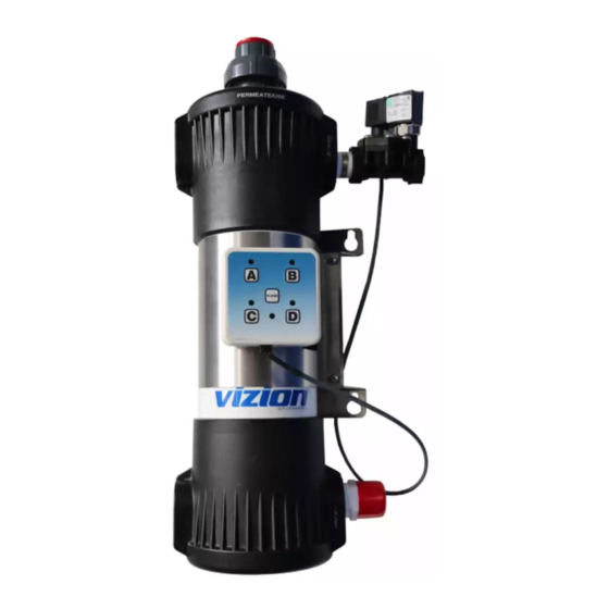
SPECIFICATIONS Model & Width Depth Height Operating Mfg. No. Weight UFL-410 11.5” 6” 20” 20 lbs. 9700459 (29 cm) (15 cm) (51 cm) (9.1 kg) Electrical Cord & Plug Configurations Electrical Ratings Model & Kit Model Volts Watts Amps Hertz Description Configuration Mfg. - Page 5 PERMEATE OUTLET DRAIN VALVE FLUSH BUTTON MOUNTING BRACKET FLOW CONTROLLER FILTER HOUSING INLET Figure 1. Components P/N 1011180 Rev. C 11/16...
-
Page 6: Performance Data Sheet
PERFORMANCE DATA SHEET Filter Cartridge Capacities Maximum Operating 100 psig (690 kPa) Pressure Maximum Operating 104°F (40°C) Temperature Minimum Operating 40°F (4°C) Temperature Maximum Trans 45 PSI (3.1 Bar) Membrane Pressure pH Range 3-10 MWCO 100 kD Do not use with water that is microbiologi- cally unsafe or of unknown quality without adequate disinfection before or after the system. -
Page 7: Overview
OVERVIEW The UFL system operates in two modes: Normal Operation Mode Flush Mode During Normal Operation Mode, water enters the Inlet and flows through the Ultra Filter before exiting the Permeate Outlet as usable product water. During Flush Mode, the Drain Valve opens and water entering the Inlet flushes and cleans the Ultra Filter membrane by remov- UNIVERSAL... -
Page 8: Installation
NOTE: If any parts are damaged, contact Pipe Wrenches to the system inlet and sized properly for A.J. Antunes & Co. IMMEDIATELY Garden Hose (for rinsing) the inlet plumbing line. at 1-800-253-2991 (toll free Hose or pipe for drain line An optional “T”... -
Page 9: Permeate Line Plumbing
Permeate Line Plumbing DRAIN LINE FROM SECURE To ensure the highest quality and safest SYSTEM water, it is recommended that a check valve (to prevent back flow) be installed in the wa- 2” (5.1 CM) MINIMUM ter line after the permeate connection. This will help prevent possible contamination of the filter system due to other equipment downstream. -
Page 10: Sanitizing The System And Lines
Sanitizing the System and Lines IMPORTANT Commonwealth of Massachusetts Plumb- The plumbing must be sanitized to elimi- ing Code 248 CMR shall be adhered to. nate possible contamination that may have The use of saddle valves are not permit- occurred during the installation process. ted, please consult your local plumber. -
Page 11: Maintenance
MAINTENANCE 14. Install the Snap Ring by guiding the non-lugged end into the groove Replacing the Ultra Filter first, pushing outward and working around the ring until it snaps into Cartridge place. Turn off water to the system by clos- NOTE: Make sure that the Snap Ring is ing the inlet valve. -
Page 12: Changing The Interval Setting
Changing the Interval Setting CAUTION Changing the flush interval can cause the Ultra Filter to plug prematurely and may reduce the life of the filter. Consult the factory for more information. Though not recommended, the Interval Setting on the controller can be changed. If the setting must be changed, use the chart below. -
Page 13: Troubleshooting
TROUBLESHOOTING Problem Possible Cause Corrective Action Unit does not have power. The power cord is not correctly plugged in. Plug power cord in correctly. The power cord is not correctly plugged in. Plug power cord in correctly. The Control Display is blank. Control Board is inoperable. - Page 14 Replacement Parts can be purchased from an authorized dealer. Contact A.J. Antunes & Co. at 1-630-754-1000 or toll free in the United States at 1-800-253-2991. Item Part # Description Qty. Item Part # Description Qty. Item Part # Description Qty.
-
Page 15: Notes
NOTES P/N 1011180 Rev. C 11/16... -
Page 16: Limited Warranty
Equipment. A.J. Antunes & Co. reserves the right to make changes in design or add any improvements on any product. The right is always reserved to modify equipment because of factors beyond our control and government regulations. Changes to update equip- ment do not constitute a warranty charge.
Need help?
Do you have a question about the UFL-410 Series and is the answer not in the manual?
Questions and answers