Endress+Hauser Ceraphant PTP31B Operating Instructions Manual
Process pressure measurement. pressure switch for safe measurement and monitoring of absolute and gauge pressure
Hide thumbs
Also See for Ceraphant PTP31B:
- Operating instructions manual (92 pages) ,
- Operating instructions manual (88 pages)

Related Manuals for Endress+Hauser Ceraphant PTP31B


Summary of Contents for Endress+Hauser Ceraphant PTP31B
- Page 1 Products Solutions Services BA01270P/00/EN/04.16 71344744 Operating Instructions Ceraphant PTP31B, PTP33B Process pressure measurement Pressure switch for safe measurement and monitoring of absolute and gauge pressure...
- Page 2 • The manufacturer reserves the right to modify technical data without prior notice. Your Endress+Hauser distributor will supply you with current information and updates to these Instructions. Endress+Hauser...
-
Page 3: Table Of Contents
15.1 Input ....... 68 15.2 Output ......Endress+Hauser... - Page 4 15.5 Process ......76 Index ........77 Endress+Hauser...
-
Page 5: Document Information
Ceraphant PTP31B, PTP33B Document information Document information Document function These Operating Instructions contain all the information that is required in various phases of the life cycle of the device: from product identification, incoming acceptance and storage, to mounting, connection, operation and commissioning through to troubleshooting, maintenance and disposal. -
Page 6: Documentation
1. 2. 3. … A, B, C, ... Views Documentation The document types listed are available: In the Download Area of the Endress+Hauser Internet site: www.endress.com → Download 1.3.1 Technical Information (TI): planning aid for your device PTP31B: TI01130P PTP33B: TI01246P The document contains all the technical data on the device and provides an overview of the accessories and other products that can be ordered for the device. -
Page 7: Terms And Abbreviations
Ceraphant PTP31B, PTP33B Document information Terms and abbreviations A0029505 Item Term/ Explanation abbreviation The OPL (over pressure limit = sensor overload limit) for the measuring device depends on the lowest-rated element, with regard to pressure, of the selected components, i.e. the process connection has to be taken into consideration in addition to the measuring cell. -
Page 8: Turn Down Calculation
Document information Ceraphant PTP31B, PTP33B Turn down calculation 1 = 2 A0029545 Calibrated/adjusted span Zero point-based span URL sensor Example • Sensor:10 bar (150 psi) • Calibrated/adjusted span: 0 to 5 bar (0 to 75 psi) • Upper range value (URL) = 10 bar (150 psi) •... -
Page 9: Basic Safety Instructions
The manufacturer is not liable for damage caused by improper or non-designated use. Verification for borderline cases: ‣ For special fluids and fluids for cleaning, Endress+Hauser is glad to provide assistance in verifying the corrosion resistance of process-wetted materials, but does not accept any warranty or liability. -
Page 10: Workplace Safety
It meets general safety standards and legal requirements. It also complies with the EU directives listed in the device-specific EU Declaration of Conformity. Endress+Hauser confirms this by affixing the CE mark to the device. -
Page 11: Product Description
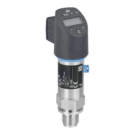
Ceraphant PTP31B, PTP33B Product description Product description Product design Overview Item Description Valve plug Cable M12 plug Housing cap made of plastic A0022015 Housing Process connection (sample illustration) A0027215 A0027227 Function 3.2.1 Calculating the pressure Devices with metallic process isolating diaphragm The process pressure deflects the metal process isolating diaphragm of the sensor and a fill fluid transfers the pressure to a Wheatstone bridge (semiconductor technology). -
Page 12: Incoming Acceptance And Product
Incoming acceptance and product identification Ceraphant PTP31B, PTP33B Incoming acceptance and product identification Incoming acceptance DELIVERY NOTE A0028673 1 = 2 A0016870 Is the order code on the delivery note (1) identical to the order code on the product sticker (2)? -
Page 13: Product Identification
Ceraphant PTP31B, PTP33B Incoming acceptance and product identification A0028673 A0022106 Is the documentation available? If required (see nameplate): Are the safety instructions (XA) present? If one of these conditions does not apply, please contact your Endress+Hauser sales office. Product identification The following options are available for identification of the measuring device: •... - Page 14 Incoming acceptance and product identification Ceraphant PTP31B, PTP33B 4.3.2 Transporting the product to the measuring point WARNING Incorrect transport! Housing and diaphragm may become damaged, and there is a risk of injury! ‣ Transport the measuring device to the measuring point in its original packaging or by the process connection.
-
Page 15: Installation
Ceraphant PTP31B, PTP33B Installation Installation Mounting dimensions For dimensions, see the "Mechanical construction" section in the Technical Information. Installation conditions • No moisture may enter the housing when installing or operating the device, or when establishing the electrical connection. • Do not clean or touch process isolating diaphragms with hard and/or pointed objects. -
Page 16: Mounting Location
Installation Ceraphant PTP31B, PTP33B Mounting location 5.4.1 Pressure measurement Functional testing can be carried out more easily if you mount the device downstream from a shutoff device. Pressure measurement in gases Mount the device with shutoff device above the tapping point so that any condensate can flow into the process. - Page 17 Ceraphant PTP31B, PTP33B Installation Pressure measurement in liquids Mount the device with a shutoff device and siphon below or at the same height as the tapping point. Advantage: • defined water column causes only minor/negligible measuring errors and • air bubbles can be released to the process.
-
Page 18: Post-Installation Check
Installation Ceraphant PTP31B, PTP33B Post-installation check Is the device undamaged (visual inspection)? Does the device conform to the measuring point specifications? For example: • Process temperature • Process pressure • Ambient temperature range • Measuring range Are the measuring point identification and labeling correct (visual inspection)? ... -
Page 19: Electrical Connection
Ceraphant PTP31B, PTP33B Electrical connection Electrical connection Connecting the measuring unit 6.1.1 Terminal assignment WARNING Risk of injury from the uncontrolled activation of processes! ‣ Switch off the supply voltage before connecting the device. ‣ Make sure that downstream processes are not started unintentionally. -
Page 20: Relay Switching Capacity
Electrical connection Ceraphant PTP31B, PTP33B 2 x PNP switch outputs R1 and R2 M12 plug Valve plug Cable 0.63A 0.63A L– L– A0023248 A0023282 brown = L+ black = switch output 1 white = switch output 2 blue = L-... -
Page 21: Connection Conditions
Ceraphant PTP31B, PTP33B Electrical connection Connection conditions 6.3.1 Cable specification For valve plug: < 1.5 mm (16 AWG) and Ø3.5 to 6.5 mm (0.14 to 0.26 in) Connection data 6.4.1 Load (for devices with analog output) The maximum load resistance depends on the terminal voltage and is calculated according... -
Page 22: Operation Options
Thus, commissioning and advanced settings and configurations are some of the tasks they have to carry out. Structure of the operating menu The menu structure has been implemented according to VDMA 24574-1 and complemented by Endress+Hauser-specific menu items. User role Submenu Meaning/use Operator (display Display/operat. -
Page 23: General Value Adjustment And Rejection Of Illegal Entries
Ceraphant PTP31B, PTP33B Operation options A0022121 Operating keys Status LED Switch output LEDs Measured value Unit General value adjustment and rejection of illegal entries Parameter (not numerical value) is flashing: parameter can be adjusted or selected. When adjusting a numerical value: the numerical value does not flash. The first digit of the numerical value starts to flash only when the ... -
Page 24: Locking And Unlocking Operation
Operation options Ceraphant PTP31B, PTP33B Locking and unlocking operation The device features • Automatic key locking • Parameter settings lock. Key locking is indicated on the local display by "E > 2". Locking of the parameter settings is indicated as soon as an attempt is made to change a parameter. - Page 25 Ceraphant PTP31B, PTP33B Operation options Navigation EF → ADM → LCK Description Use this function to enter the code (which was defined in the COD parameter) to enable configuration. Keys are evaluated but parameters are read only. The parameters can only be changed after unlocking.
-
Page 26: Navigation Examples
Operation options Ceraphant PTP31B, PTP33B Navigation examples 7.7.1 Parameters with a picklist Example: Display measured value rotated by 180° Menu path: EF → DIS → DRO Press or key until "DRO" is displayed. Initial setting is "NO" (display not rotated). -
Page 27: Commissioning
Ceraphant PTP31B, PTP33B Commissioning Commissioning If an existing configuration is changed, measuring operation continues! The new or modified entries are only accepted once the setting has been made. WARNING Risk of injury from the uncontrolled activation of processes! ‣ Make sure that downstream processes are not started unintentionally. - Page 28 Commissioning Ceraphant PTP31B, PTP33B Prerequisite: This is a theoretical calibration, i.e. the pressure values for the lower and upper range are known. It is not necessary to apply pressure. Due to the orientation of the device, there may be pressure shifts in the measured value, i.e.
-
Page 29: Performing Position Adjustment
Ceraphant PTP31B, PTP33B Commissioning 8.4.2 Calibration with reference pressure (wet calibration = calibration with medium) Example: In this example, a device with a 400 mbar (6 psi) sensor is configured for the measuring range 0 to 300 mbar (0 to 4.4 psi). - Page 30 Commissioning Ceraphant PTP31B, PTP33B Prerequisite An offset is possible (parallel shifting of the sensor characteristic) to correct the orientation and any zero point drift. The set value of the parameter is subtracted from the "raw measured value". The requirement to be able to perform a zero point shift without changing the span is met with the offset function.
- Page 31 Ceraphant PTP31B, PTP33B Commissioning Example 1 • Measured value = 2.2 mbar (0.033 psi) • You use the "GTZ" parameter to correct the measured value with the value, e.g. 2.2 mbar (0.033 psi). This means that you are assigning the value 0 mbar (0 psi) to the pressure present.
-
Page 32: Configuring Process Monitoring
Commissioning Ceraphant PTP31B, PTP33B Configuring process monitoring To monitor the process, it is possible to specify a pressure range which is monitored by the limit switch. Depending on the device version, the process can be monitored using one PNP switch output, or optionally using a second PNP switch output or an analog 4 to 20 mA output. - Page 33 Ceraphant PTP31B, PTP33B Commissioning Note The hysteresis is implemented using the "SP1/SP2" and "RP1/RP2" parameters. Since the parameter settings depend on one another, the parameters are described all together. • SP1 = switch output 1 • SP2 = switch output 2 (optional) •...
- Page 34 Commissioning Ceraphant PTP31B, PTP33B 8.7.2 Window function • SP1 = switch output 1 • SP2 = switch output 2 (optional) FH1/FH2 Upper value for pressure window, output 1/2 FL1/FL2 Lower value for pressure window, output 1/2 Navigation FH1/FH2 FL1/FL2 Note The window function is implemented using the "FH1/FH2"...
-
Page 35: Current Output
Ceraphant PTP31B, PTP33B Commissioning Prerequisite • This function is only available if the window function has been defined for the switch output. • The upper value of the pressure window "FH1/FH2" must be greater than the lower value of the pressure window "FL1/FL2"! A diagnostic message is displayed if the upper value entered for the pressure window "FH1/FH2"... - Page 36 Commissioning Ceraphant PTP31B, PTP33B Selection No selection. The user is free to edit the values. Factory setting Upper measuring limit or as per order specifications. GTL Pressure applied for 4mA (LRV) Navigation EF → I → GTL Description The pressure value present is automatically adopted for the 4 mA current signal.
-
Page 37: Application Examples
Ceraphant PTP31B, PTP33B Commissioning Description The pressure value present is automatically adopted for the 20 mA current signal. Parameter for which the current range can be assigned to any section of the nominal range. This occurs by assigning the pressure lower range value to the lower measuring current and the pressure upper range value to the upper measuring current. -
Page 38: Protecting Settings From Unauthorized
Commissioning Ceraphant PTP31B, PTP33B 8.11 Protecting settings from unauthorized access → 24 Endress+Hauser... -
Page 39: Diagnostics And Troubleshooting
Ceraphant PTP31B, PTP33B Diagnostics and troubleshooting Diagnostics and troubleshooting Troubleshooting If an illegal configuration exists in the device, the device switches to error mode. Example: • Diagnostic message "C469", for example, appears on the local display, the status LED is lit red and the background of the local display changes from white to red. -
Page 40: Diagnostic Events
Diagnostics and troubleshooting Ceraphant PTP31B, PTP33B Diagnostic events 9.2.1 Diagnostic message Faults detected by the self-monitoring system of the measuring device are displayed as a diagnostic message in alternation with the measured value display. Status signals The table lists the messages that may occur. The ALARM STATUS parameter shows the message with the highest priority. - Page 41 Ceraphant PTP31B, PTP33B Diagnostics and troubleshooting 9.2.2 List of diagnostic events Diagnostic event Cause Corrective measure Code Description No error C431 Invalid position adjustment The calibration performed would cause the Position adjustment + parameter of the current output sensor nominal range to be exceeded or must be within the sensor nominal range undershot.
-
Page 42: Behavior Of The Device In The Event Of A Fault
Diagnostics and troubleshooting Ceraphant PTP31B, PTP33B Diagnostic event Cause Corrective measure Code Description Current output not Current output not connected • Connect current output with load. connected • If the current output is not required, switch the current output off via the configuration. -
Page 43: Behavior Of The Device In The Event Of A Voltage Drop
Ceraphant PTP31B, PTP33B Diagnostics and troubleshooting The behavior of the current output in case of fault is defined by the following parameters: • FCU "MIN": Lower alarm current (≤3.6 mA) (optional, see the following table)→ 58 • FCU "MAX" (factory setting): Upper alarm current (≥21 mA) → 58 •... -
Page 44: Maintenance
Maintenance Ceraphant PTP31B, PTP33B Maintenance No special maintenance work is required. Keep the pressure compensation element (1) free from contamination. A0022140 10.1 Exterior cleaning Please note the following points when cleaning the device: • The cleaning agents used should not corrode the surface and the seals. -
Page 45: Repair
The measuring device must be returned if the wrong device has been ordered or delivered. As an ISO-certified company and also due to legal regulations, Endress+Hauser is obliged to follow certain procedures when handling any returned products that have been in contact with medium. -
Page 46: Overview Of The Operating Menu
Overview of the operating menu Ceraphant PTP31B, PTP33B Overview of the operating menu Depending on the parameter configuration, not all submenus and parameters are available. Information on this can be found in the parameter description under "Prerequisite". Switch output Level 1 Level 2 Level 3 Description... - Page 47 Ceraphant PTP31B, PTP33B Overview of the operating menu Switch output Level 1 Level 2 Level 3 Description Details 1 x PNP 2 x PNP 1 x PNP + 4 to 20 mA alarm current → 58 In the event of an error: MIN (≤3.6 mA) In the event of an error: MAX (≥21 mA)
- Page 48 Overview of the operating menu Ceraphant PTP31B, PTP33B Switch output Level 1 Level 2 Level 3 Description Details 1 x PNP 2 x PNP 1 x PNP + 4 to 20 mA Simulation output 2 → 65 ...
-
Page 49: Description Of Device Parameters
Ceraphant PTP31B, PTP33B Description of device parameters Description of device parameters 13.1 Switch output 1 and switch output 2 13.1.1 Hysteresis (Switch point and switchback point) SP1/SP2 switch point value, output 1/2 RP1/RP2 switchback point value, output 1/2 Navigation SP1/SP2... - Page 50 Description of device parameters Ceraphant PTP31B, PTP33B Prerequisite • These functions are only available if the hysteresis function has been defined for the switch output. • The configured value for the switch point "SP1/SP2" must be greater than the switchback point "RP1/RP2"!
- Page 51 Ceraphant PTP31B, PTP33B Description of device parameters 13.1.2 Window function • SP1 = switch output 1 • SP2 = switch output 2 (optional) FH1/FH2 Upper value for pressure window, output 1/2 FL1/FL2 Lower value for pressure window, output 1/2 Navigation...
- Page 52 Description of device parameters Ceraphant PTP31B, PTP33B Prerequisite • This function is only available if the window function has been defined for the switch output. • The upper value of the pressure window "FH1/FH2" must be greater than the lower value of the pressure window "FL1/FL2"!
-
Page 53: Current Output
Ceraphant PTP31B, PTP33B Description of device parameters 13.2 Current output STL value for 4 mA (LRV) Navigation Description Assignment of the pressure value which should correspond to the 4 mA value. It is possible to invert the current output. To do so, assign the pressure upper range value to the lower measuring current. -
Page 54: Ef Menu (Extended Functions)
Description of device parameters Ceraphant PTP31B, PTP33B 13.3 EF menu (extended functions) RES Reset Navigation EF → RES Description WARNING Confirming the reset by selecting "YES" causes an immediate device reset to the factory settings of the order configuration. If the factory settings have been changed, downstream processes might be affected following a reset (the behavior of the switch output or current output might be changed). -
Page 55: Hno No Contact For Hysteresis Function
Ceraphant PTP31B, PTP33B Description of device parameters Description To prevent constant switch-on and switch-off if values are around the switch point "SP1/ SP2" or the switchback point "RP1/RP2", a delay in a range of 0 – 50 seconds, to two decimal places, can be set for the individual points. -
Page 56: Hnc Nc Contact For Hysteresis Function
Description of device parameters Ceraphant PTP31B, PTP33B Navigation EF → Ou1 → HNO EF → Ou2 → HNO Description If this parameter is selected, the switch output is defined as an NO contact with a hysteresis property. Navigate to the parameter and press the key. -
Page 57: Yes
Ceraphant PTP31B, PTP33B Description of device parameters Navigation EF → I → GTL Description The pressure value present is automatically adopted for the 4 mA current signal. Parameter for which the current range can be assigned to any section of the nominal range. -
Page 58: Fcu Alarm Current
Description of device parameters Ceraphant PTP31B, PTP33B FCU Alarm current Navigation EF → FCU Description The device displays warnings and faults. This is done on the local display via the diagnostic message stored in the device. The purpose of all device diagnostics is solely to provide information to the user;... -
Page 59: Uni Unit Changeover
Ceraphant PTP31B, PTP33B Description of device parameters Selection • NO (current output remains switched on) • YES (current output is switched off) Factory setting ON Switch on current output Navigation EF → I → ON Description Switches on the current output. -
Page 60: Lo Min Value (Minimum Indicator)
Description of device parameters Ceraphant PTP31B, PTP33B LO Min value (minimum indicator) Navigation EF → LO Description This parameter (also known as the minimum indicator) makes it possible to call up retroactively the lowest value ever measured for pressure. A pressure that is present for at least 2.5 ms is logged to the maximum indicator. -
Page 61: Tau Damping
Ceraphant PTP31B, PTP33B Description of device parameters Navigation EF → GTZ Description The pressure resulting from the orientation of the device can be corrected here. The pressure difference between zero (set point) and the measured pressure need not be known. -
Page 62: Dva Pv Display Measured Value
Description of device parameters Ceraphant PTP31B, PTP33B DVA Measured value display Navigation EF → DIS → DVA Description Configuration of the measured value display and display of the configured switch point. Selection • PV = display measured value • PV,/' = display measured value as a percent (only for devices with a current output) –... -
Page 63: Cod Locking Code
Ceraphant PTP31B, PTP33B Description of device parameters Description Use this function to enter the code (which was defined in the COD parameter) to enable configuration. Keys are evaluated but parameters are read only. The parameters can only be changed after unlocking. -
Page 64: Diag Menu (Diagnosis)
Description of device parameters Ceraphant PTP31B, PTP33B 13.4 DIAG menu (diagnosis) STA Current device status Navigation DIAG → STA Description Displays the current device status. LST Last device status Navigation DIAG → LST Description Displays the last device status (error or warning) which has been rectified during operation. - Page 65 Ceraphant PTP31B, PTP33B Description of device parameters Description Analog output simulation. If a simulation is active, a warning to this effect is displayed so that it is obvious to the user that the device is in the simulation mode. A visual warning is indicated on the local display (C485 - Simulation Active).
-
Page 66: Accessories
Accessories Ceraphant PTP31B, PTP33B Accessories 14.1 Weld-in adapter Various weld-in adapters are available for installation in vessels or pipes. Device Description Option Order number PTP33B Weld-in adapter M24, d=65, 316L 71041381 PTP33B Weld-in adapter M24, d=65, 316L 3.1 EN10204-3.1 71041383... -
Page 67: M12 Plug Connectors
Ceraphant PTP31B, PTP33B Accessories 14.3 M12 plug connectors Connector Degree of protection Material Option Order number IP67 • Union nut: Cu Sn/Ni 52006263 (self-terminated connection • Body: PBT at M12 plug) • Seal: NBR 53 (2.09) A0024475 M12 90 degrees IP67 •... -
Page 68: Technical Data
Technical data Ceraphant PTP31B, PTP33B Technical data 15.1 Input 15.1.1 Measured variable Measured process variable Gauge pressure or absolute pressure Calculated process variable Pressure 15.1.2 Measuring range Metal process isolating diaphragm Sensor Device Maximum Lowest Factory settings Option Sensor measuring range... - Page 69 Ceraphant PTP31B, PTP33B Technical data Sensor Device Maximum Lowest Factory settings Option Sensor measuring range calibratable span lower (LRL) upper (URL) [bar (psi)] [bar (psi)] [bar (psi)] [bar (psi)] [bar (psi)] Devices for absolute pressure measurement 400 mbar (6 psi)
-
Page 70: Output
Technical data Ceraphant PTP31B, PTP33B 15.2 Output 15.2.1 Output signal Description Option PNP switch output + 4 to 20 mA output (4-wire) PNP switch output (3-wire) 2 x PNP switch output (4-wire) Product Configurator, order code for "Output" 15.2.2 Range of adjustment •... - Page 71 Ceraphant PTP31B, PTP33B Technical data [ ] W 1022 6.5V max £ 23mA A0031107 Power supply 10 to 30 V DC maximum load resistance Lmax Supply voltage When excessively high load: • Output of the fault current and display of " S803 "...
- Page 72 Technical data Ceraphant PTP31B, PTP33B alarm current Device Description Option PTP31B Adjusted min. alarm current PTP33B PTP31B 1 low ≤3.6 mA PTP33B 2 high ≥21 mA 3 last current value Product Configurator order code for "Service" Product Configurator order code for "Calibration/unit"...
-
Page 73: Performance Characteristics Of Metallic
Ceraphant PTP31B, PTP33B Technical data 15.3 Performance characteristics of metallic process isolating diaphragm 15.3.1 Reference operating conditions • As per IEC 60770 • Ambient temperature T = constant, in the range of:+21 to +33 °C (+70 to +91 °F) • Humidity φ = constant, in the range of 5 to 80 % rH •... - Page 74 Technical data Ceraphant PTP31B, PTP33B 15.3.6 Thermal change of the zero output and the output span PTB31B Measuring cell –20 to +85 °C (–4 to +185 °F) –20 to –40 °C (–4 to –40 °F) +85 to +100 °C (+185 to +212 °F) % of the calibrated span for TD 1:1 <1 bar (15 psi)
-
Page 75: Environment
Ceraphant PTP31B, PTP33B Technical data 15.4 Environment 15.4.1 Ambient temperature range Device Ambient temperature range PTP31B –20 to +70 °C (–4 to +158 °F) PTP33B Exception: the following cable is designed for an operating temperature range of –25 to +70 °C (–13 to +158 °F): Product Configurator order code for "Accessory enclosed", option "RZ". -
Page 76: Process
Frequent extreme changes in temperatures can temporarily cause measuring errors. Internal temperature compensation is faster the smaller the change in temperature and the longer the time interval. For further information please contact your local Endress+Hauser Sales Center. 15.5.2 Pressure specifications... -
Page 77: Index
LST ........64 Endress+Hauser... - Page 78 Index ZRO ........29, 60 Endress+Hauser...
- Page 80 *71344744* 71344744 www.addresses.endress.com...
Need help?
Do you have a question about the Ceraphant PTP31B and is the answer not in the manual?
Questions and answers