Honeywell EXCEL 5000 Product Data
Distributed i/o
Hide thumbs
Also See for EXCEL 5000:
- User manual (282 pages) ,
- Installation instructions manual (8 pages) ,
- Installation instructions (2 pages)
Advertisement
Quick Links
Download this manual
See also:
User Manual
HONEYWELL EXCEL 5000 OPEN SYSTEM
GENERAL
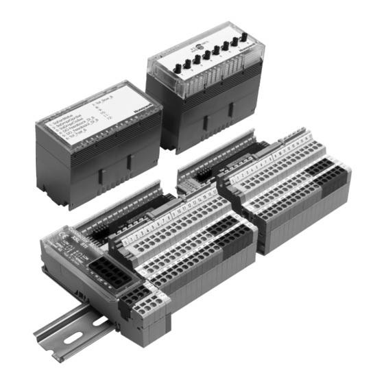
The XFL521B, 522B, 523B, and 524B modules are L
compliant digital and analog I/O modules which can be
installed at strategic locations within a building. These
modules convert sensor readings and provide output signals
used for operating actuators via L
variables (SNVTs). Each Distributed I/O module plugs into a
base terminal block allowing communication with controllers
®
via the built-in Echelon
L
W
ON
minal block provides spring clamp terminals for easy connec-
tion of field cables from the various sensors and actuators.
The modular system allows DI/O's to be removed from the
system without disturbing other modules. The module with
terminal block mounts easily onto a DIN rail.
When using CARE, the DI/O's can be automatically bound
and commissioned to the Excel 500 CPU (XC5010C,
XC5210C, XCL5010) and XL50. When the modules are used
by other controllers, provided plug-ins permit the modules to
be commissioned by CARE 4.0 or by any LNS network
management tool.
® U.S. Registered Trademark
Copyright © 2016 Honeywell Inc. • All Rights Reserved
M
ON
ARK
W
standard network
ON
ORKS
bus interface. The ter-
ORKS
Distributed I/O
523B, AND 524B MODULES
FEATURES
L
M
™ compliant
ON
ARK
®
2-wire L
W
bus interface between controller
ON
ORKS
and I/O
No additional field terminals required
Usable with Excel 500 controllers in conjunction with
standard internal I/O modules
Automatic binding and commissioning to Excel 500
controllers when using CARE
Connector module with sliding bus connector
(eliminating the need to wire together neighboring
modules)
Fast connection due to spring clamp terminals
Module exchange during operation
Alarm in case of defective module
Mechanical coding prevents mismatching of modules
Power LED (L1, green) and L
red) on all electronics modules
Status LEDs for outputs and digital inputs
Optional manual override modules for analog and
digital output modules with feedback
XILON for wiring test
DESCRIPTION
These Distributed I/O modules use a Neuron® chip and an
FTT-10A free topology transceiver for communication on a
L
W
bus and comply with L
ON
ORKS
Guidelines V3.2.
Table 1. Modules and accessories
iItem
XFL521B
Analog input module
XFL522B
Analog output module
XFL523B
Digital input module
XFL524B
Digital output module
XSL511
L
W
connector module
ON
ORKS
XSL512
Manual terminal disconnect module
XSL513
Terminal block for XFL521x, 522x, 523x
XSL514
Terminal block for XFL524x
XFR522A
Analog output manual override module
XFR524A
Digital output manual override module
XAL-Code
To prevent mismatching modules
XAL-Term2
Interface to the L
XAL 2
Cover release tool
XAL 1
Swivel label (for manual override modules)
XFL521B, 522B,
PRODUCT DATA
W
service LED (L2,
ON
ORKS
M
Application Layer
ON
ARK
description
W
bus
ON
ORKS
EN0B-0090GE51 R0316
Advertisement

Related Manuals for Honeywell EXCEL 5000


Summary of Contents for Honeywell EXCEL 5000
- Page 1 To prevent mismatching modules management tool. XAL-Term2 Interface to the L ORKS XAL 2 Cover release tool XAL 1 Swivel label (for manual override modules) ® U.S. Registered Trademark Copyright © 2016 Honeywell Inc. • All Rights Reserved EN0B-0090GE51 R0316...
- Page 2 DISTRIBUTED I/O – PRODUCT DATA INTEROPERABILITY the Distributed I/O module to set its location string. If a The Distributed I/O modules are compliant to the L network management node commands this nci to Application Layer Interface Guidelines, version 3.2. The “CFG_EXTERNAL”, then the module will no longer modify its modules contain a L Node Object to allow monitoring...
- Page 3 DISTRIBUTED I/O – PRODUCT DATA Table 3. Node Object network variables NV name type range description RQ_NORMAL Upon receiving an update to nviRequest, nvoStatus is RQ_DISABLE updated. RQ_ENABLE RQ_SELF_TEST is used only in the XFL522B analog nviRequest SNVT_obj_request RQ_UPDATE_STATUS output module for outputs configured as a motor. In this RQ_REPOPRT_MASK case, a synchronization is performed to set the actuator RQ_SELF_TEST...
- Page 4 DISTRIBUTED I/O – PRODUCT DATA If the distance between the controller and actuator or sensor with 24 Vac supply is greater than 550 ft (170 m), a separate external transformer for the actuator or sensor is necessary. PRIMARY VOLTAGE 24 V 24 V 24 Vac TRANSFORMER...
-
Page 5: Technical Data
DISTRIBUTED I/O – PRODUCT DATA TECHNICAL DATA Analog Input Module XFL521B Eight inputs (AI1 – AI8) 0...10 Vdc (see EN1R-1047 for impedance information) 0...20 mA (via external 500-Ω resistor) 4...20 mA (via external 500-Ω resistor) NTC 20kΩ (-50 °C to +150 °C) PT1000 (-50 °C to +150 °C) ... - Page 6 DISTRIBUTED I/O – PRODUCT DATA NOTE: When the input is identified as a DI point, the Active sensors (0 (4) to 20 mA): internal pull-up resistor is disabled (see Fig. 6). Immersion temperature sensor VF 100 Air duct temperature sensor LF 100 Analog input high impedance Analog input low impedance (selectable in CARE)
- Page 7 DISTRIBUTED I/O – PRODUCT DATA Analog Output Module XFL522B Eight outputs (AO1 – AO8), short-circuit proof Signal levels 0...10 Vdc = 11 Vdc, I = +1 mA, -1 mA Protected outputs up to 40 Vdc / 24 Vac ...
- Page 8 DISTRIBUTED I/O – PRODUCT DATA Table 8. L Object NVs for the XFL522B NV name type range description nviValue SNVT_switch Receives the value for the output channel. Transmits the feedback value of the actuator output. If the manual override switch is set to 0, or if the manual override module is not plugged in, the feedback output reflects the value of nviValue.
- Page 9 Attention: Always connect the same side of the transformer to the same side of XSL511. Connector Module Connector Module XSL 511 XSL 511 shield shield shield shield Honeywell AG Made in Germany Honeywell AG Made in Germany Fig. 11. XFL522B analog output module EN0B-0090GE51 R0316...
- Page 10 DISTRIBUTED I/O – PRODUCT DATA Digital Input Module XFL523B Twelve inputs (DI1 – DI12) R = 10kΩ Max. 20 Hz input frequency ON/OFF state: OFF: U 2.5 Vdc; ON: U 5 Vdc Protected switching up to 40 Vdc / 24 Vac ...
- Page 11 DISTRIBUTED I/O – PRODUCT DATA Table 9. Relation between contact position and logical status for DI1-6 (LED switch 1) and DI7-12 (LED switch 2) of the XFL523B contact position NO/NC attribute logical status input voltage LED switch on LED switch off ...
- Page 12 DISTRIBUTED I/O – PRODUCT DATA Digital Output Module XFL524B Six isolated change-over contacts Max. voltage U = 230 Vac per output Max. current I = 2 A per output LED per channel OFF: LED off ON: LED illuminated (yellow) ...
- Page 13 DISTRIBUTED I/O – PRODUCT DATA Table 11. Relation between contact position and logical status for the XFL524B relay on/off NO/NC attribute logical status LED status Table 12. L Object NVs for the XFL524B NV name type range description nviValue SNVT_switch Receives the value for the output channel.
- Page 14 DISTRIBUTED I/O – PRODUCT DATA Terminal Block XSL513 for XFL521B/522B/523B Mounts on a DIN rail (top-hat rail) Spring-clamp terminals Safety latch secures XFL module in its position Mechanical coding using coding pins; an optional package with 20 coding combs is available (XAL-Code) The XSL513 Terminal Block has three rows of terminals: Top row: 18 signal terminals (gray);...
- Page 15 DISTRIBUTED I/O – PRODUCT DATA Manual Override Module XFR522A for XFL522B (Analog Output) Mounts on top of the XFL522B module Potentiometer settings automatic or variable 0 – 100% XFL522B LEDs remain visible Dimensions (WxLxH): 47x97x20 mm ...
-
Page 16: Terminal Block Connection
DISTRIBUTED I/O – PRODUCT DATA Terminal Block Connection connector module, however, if mounting vertically, it is re- commended that you mount it at the bottom to ensure a good NOTE: The terminal blocks are to be mounted on 1.5-inch connection of the bus in case of slippage on the DIN rail. (35-mm) DIN rails (DIN/EN 50 022 35x15). - Page 17 DISTRIBUTED I/O – PRODUCT DATA Install 3 -party DIN rail end bracket close to end cover other to ensure proper contact at the sliding bus of the last module. connector. NOTE: It is recommended that you use solid standard 3 Mount the type-C safety latches to provide extra party DIN rail end brackets on both ends of the assurance that adjacent terminal blocks will not...
- Page 18 DISTRIBUTED I/O – PRODUCT DATA Manual Terminal Disconnect Module XSL512 Mounts between terminal blocks and Distributed I/O modules Manual terminal disconnect switches 18 disconnect switches Dimensions (WxLxH): 58x97x55 mm Safety latch secures XFL module in its position The XSL512 Manual Terminal Disconnect module allows each of the terminal block's input connections to be manually disconnected from the plugged-in module.
-
Page 19: Setting The Module Address
DISTRIBUTED I/O – PRODUCT DATA All modules will report the setting of the 16-position rotary CAUTION HEX switch as a 2-byte ASCII number in the lowest 2 bytes of the Neuron® chip’s location string. Changing the rotary HEX Mixing the modules can destroy them. switch setting causes the module to reset its application configuration (sensor selection, output selection, motor runtime, etc.) and go unconfigured. -
Page 20: Installing The I/O Modules
DISTRIBUTED I/O – PRODUCT DATA 1. Switch off the power to the output module; or unlock the safety latch and unplug the module from the terminal block as described in section "Removing Modules and Terminal Blocks". 2. Remove the standard cover of the module housing (XFL522B/XFL524B) as described in section "Setting the Module Address". - Page 21 DISTRIBUTED I/O – PRODUCT DATA Removing Modules and Terminal Blocks The electronics modules and terminal blocks can be removed by carrying out the following steps: 1. Unlock the safety latch(es) as is depicted in Fig. 33. on terminal blocks on XSL512 Fig.
- Page 22 NOTE: The cable types listed above are as recommended ments. by Echelon® in their FTT-10A User Guide. The cable recommended by Honeywell is the level IV, 22 AWG, solid core, non-shielded cable. Belden part numbers Applying CARE Printout Labels are 9H2201504 (plenum) and 9D220150 (non- plenum).
- Page 23 DISTRIBUTED I/O – PRODUCT DATA NOTE: In the event that the limit on the total wire length is device exceeded, then FTT physical layer repeaters (FTT 10A) can be added to interconnect segments device device and increase the overall length by an amount equal device device to the original specification for that cable type and...
- Page 24 DISTRIBUTED I/O – PRODUCT DATA XFL52xB modules can be used as third-party devices with modules (XFL52x, XFL52xA), but only in the local other L compliant products, independently of an Excel mode (max 16 modules per CPU and no other 500 controller. controllers on the L bus).
- Page 25 When Distributed I/O modules are used exclusively by the NVs of a max. of 16 Distributed I/O modules assigned Honeywell Excel 500 controllers, it is possible to auto- (manually) exclusively to the host Excel 500 controller. matically bind their NVs to the controller. This is referred to as "autobinding."...
- Page 26 DISTRIBUTED I/O – PRODUCT DATA IMPORTANT: contradictory and unreliable assignments. There will be incomplete Distributed I/O module lists displayed, The autobound NVs of a controller are not visible to and there is the danger that one controller will take network management tool, and there ORKS away an existent assignment from another is hence no danger that a careless user will attempt...
- Page 27 LED (L2) is used ORKS for diagnosing the state of the Distributed I/O module (see below). Please contact Honeywell if the above actions do not solve the problem. Service Pin Message and LED A service pin message is sent when ...
- Page 28 DISTRIBUTED I/O – PRODUCT DATA In the case of a power-up or reset, the service pin message Table 21. Service LED behavior descriptions is delayed a random time between 1 and 5 seconds to context meaning avoid an overload of a network management node Power-up of Bad node hardware.
- Page 29 DISTRIBUTED I/O – PRODUCT DATA Environmental Ratings Operating temperature: 32° to 122°F (0° to 50°C) Shipping/storage temperature: -13° to 150°F (-25° to 65°C) Relative humidity (operation and storage): 5% to 90%, non-condensing Applicable Literature EN0B-091 Excel 100/500/600 System Overview ...
-
Page 30: Side View
Fig. 48. Outside dimensions of XSL513/514 terminal blocks and mounted modules (side view) Manufactured for and on behalf of the Environmental & Energy Solutions Division of Honeywell Technologies Sàrl, Rolle, Z.A. La Pièce 16, Switzerland by its Authorized Representative: Automation and Control Solutions Honeywell GmbH Böblinger Strasse 17...
Need help?
Do you have a question about the EXCEL 5000 and is the answer not in the manual?
Questions and answers