Table of Contents
Advertisement
Advertisement
Table of Contents

Subscribe to Our Youtube Channel
Related Manuals for SMA MLX 60


Summary of Contents for SMA MLX 60
- Page 1 SMA Solar Technology AG Solar Inverters MLX Series Design Guide www.SMA.de...
-
Page 2: Table Of Contents
Contents Contents 1 Introduction 1.1 Introduction 1.2 List of Abbreviations 2 Inverter Overview 2.1 Product Label 2.2 Mechanical Overview of the Inverter 2.3 Description of the Inverter 2.3.1 System Overview 2.3.2 Functional Safety 2.3.3 Operation Modes 2.4 MPP Tracker and Derating 2.4.1 MPP Tracker 2.4.2 Inverter Derating 2.4.3 Power Reference... - Page 3 Contents 4.2.1.5 PV to Earth Resistance 4.2.1.6 Earthing 4.2.1.7 Parallel Connection of PV Arrays 4.2.1.8 PV Cable Dimensions and Layout 4.2.2 Determining Sizing Factor for PV Systems 4.2.3 Thin Film 4.2.4 Internal Surge Overvoltage Protection 4.2.5 Thermal Management 4.2.6 Simulation of PV 4.2.7 PV Field Capacitance 4.3 AC Side 4.3.1 Requirements for AC Connection...
-
Page 4: Introduction
(VAr). These documents are available from the download area at S is the symbol for apparent power and is www.sma.de, or from the supplier of the solar inverter. measured in volt-amperes (VA). L00410648-02_02 / Rev. date: 2014-10-03... - Page 5 Introduction Abbreviation Description Standard Test Conditions Software Total Harmonic Distortion TN-S Terra Neutral - Separate. AC Network TN-C Terra Neutral - Combined. AC Network TN-C-S Terra Neutral - Combined - Separate. AC Network Terra Terra. AC Network Table 1.1 Abbreviations L00410648-02_02 / Rev.
-
Page 6: Inverter Overview
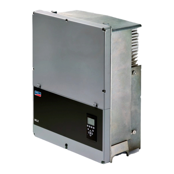
PV load switch • Ancillary service functionalities • Transformerless • 3-phase • 3-level inverter bridge with a high performance • Integrated residual current monitoring unit. Illustration 2.2 Product Label MLX 60 UL • Insulation test functionality. L00410648-02_02 / Rev. date: 2014-10-03... -
Page 7: System Overview
Inverter Overview • Extended fault ride through capabilities (to must have a DHCP server (router) as the Inverter Manager support reliable power generation during grid requires automatic IP assignment. It is recommended to faults) - depending on inverter configuration use professional grade routers and switches. The Inverter Manager provides: •... - Page 8 Inverter Overview PV strings DC combiner MLX inverter MLX Inverter Manager Router LCS tool Portal SCADA system Weather station I/O box Grid management Transformer station Illustration 2.4 System Overview L00410648-02_02 / Rev. date: 2014-10-03...
-
Page 9: Functional Safety
Inverter Overview Illustration 2.5 Overview of Installation Area Single-fault Immunity PELV (Safe to touch) The functional safety circuit has a fully redundant built-in Equipment grounding single-fault detection. If a fault occurs, the inverter Ethernet interface x 2 disconnects from the grid immediately. The method is RS-485 interface (not in use) active and covers all circuitry within the residual current Live Part... -
Page 10: Operation Modes
Inverter Overview starts to energise the grid. During grid connection, the Status LEDs inverter measures the continuous leakage current in the Green - - - - - - - - - - - - - - - - - Off grid system. -
Page 11: Mpp Tracker And Derating
Inverter Overview • inverter will remain in fail safe mode until power has been AC power limitation by setting or external absent for a minimum of 10 minutes, or the inverter has command (PLA) been shut down completely (AC+PV). Each MLX inverter limits the AC output power according to 2.4 MPP Tracker and Derating the actual power reference, which will be the lowest of the following values:... -
Page 12: Grid Code
Changing these default grid code parameters requires a customised grid code file, supplied by SMA. See 2.7 Functional Safety Settings about how to apply for customised grid code parameters. NOTICE... -
Page 13: Grid Protection Settings
Inverter Overview 2.5.1 Grid Protection Settings ‘clearance time’, the inverters cease to energise the grid The grid protection settings are stored in each inverter. • Rate of change of frequency (ROCOF). The ROCOF They ensure protection of the grid in case of certain grid values (positive or negative) are compared to the events regardless of the connection to the Inverter trip settings. -
Page 14: Reactive Power Management
Inverter Overview Q(U) Reactive power injected as a function of the grid voltage. Q(P) Reactive power injected as a function of the active output power. Q(S) Reactive power injected as a function of the apparent output power. Q(T) Reactive power injected as a function of the ambient temperature. -
Page 15: Active Power Management
Apparent power management require alterations during installation to allow optimisation The inverter can support the local grid by setting a of the local grid. Contact SMA for a custom grid code. maximum apparent power limit. • Fixed Sref – maximum apparent power limit... -
Page 16: System Planning - Mechanical
System Planning – Mechanica... 3 System Planning – Mechanical The aim of this section is to provide general information for planning the mechanical installation of the MLX inverter, including mounting and cable specifications. 3.1 Unpacking Contents: • Inverter Illustration 3.4 Ensure Adequate Air Flow •... -
Page 17: Installation Conditions
System Planning – Mechanica... 3.2.1 Installation Conditions Parameter Specification −25 °C – +60 °C (possible power derating above 45 °C) (−13 °F – 140 °F) (possible power Operational temperature range derating above 113 °F) −40 °C – +60 °C (−40°F – 140 °F) Storage temperature Relative humidity 95% (non-condensing) -
Page 18: Mounting The Inverter
System Planning – Mechanica... 3.3 Mounting the Inverter Illustration 3.8 Safe Clearances NOTICE Ensure 620 mm/24 inches base clearance for adequate airflow. L00410648-02_02 / Rev. date: 2014-10-03... -
Page 19: How To Position The Inverter
System Planning – Mechanica... Illustration 3.10 Position the Inverter Illustration 3.9 Mounting Plate NOTICE Use of the mounting plate delivered with the inverter is mandatory. If the inverter is mounted without the mounting plate, the warranty becomes void. It is strongly recommended to use all 6 mounting holes. -
Page 20: Torque Specifications For Installation
System Planning – Mechanica... 3.3.2 Torque Specifications for Installation CAUTION If the blind plugs are removed (see (7) in Illustration 3.12), use fittings with type rating: 3, 3S, 4, 4X, 6, 6P. Illustration 3.12 Overview of Inverter with Torque Indications Parameter Tool Tightening Torque... -
Page 21: System Planning - Electrical
Table 4.1. location. If the module operating temperature is not well- defined, check local common practice. This calculation Parameter MLX 60 implies a maximum of 23–26 modules per string, for MPP trackers/Inputs per MPPT 1/1 (external string combining) standard 60-cells c-Si modules. It depends on the local... -
Page 22: Short-Circuit Current
NOTICE 4.2.1.7 Parallel Connection of PV Arrays SMA can support you in the analysis of the yield losses due to MPP range for your particular project and in the The MLX inverter has 1 input and 1 MPPT. An external selection of the best technical approach. -
Page 23: Determining Sizing Factor For Pv Systems
System Planning – Electrica... string combiner plus the length of the PV cables The MLX inverter supports different sizing factors, included in the modules depending on the number of modules per string and number of strings per inverter. • The total length for the combined line is defined Any configuration that observes the varying conditions for as twice the physical distance between the string different applications: the limits in Table 4.1 for short-circuit... -
Page 24: Thermal Management
System Planning – Electrica... The thermal management concept of the inverter is based on forced cooling with speed-controlled fans. The fans are electronically controlled and are only active when needed. The rear of the inverter is designed as a heat sink that removes the heat generated by the power semiconductors in the integrated power modules. -
Page 25: Ac Side
System Planning – Electrica... capacitive leakage current can provoke undesired tripping Current sensitivity Maximum value of earth resistance of the RCMU class B of the MLX inverter, and, as a result, 20 A 2.5 Ω the disconnection of the inverter from the grid. 10 A 5 Ω... -
Page 26: Grid Impedance
ZtrafoLVMV is the short-circuit impedance of the LV/MV transformer unit as stated in the transformer datasheet (if non-existent then use a default 6%). For MLX 60 kVA inverter, the maximum total system impedance Ztotal value is 30%. 4.3.4 AC Cable Considerations... -
Page 27: Communication And System Planning, Inverter Manager
MLX inverters Illustration 5.1 Commissioning of Inverters Using LCS Tool WARNING LCS Tool Router/DHCP SMA accepts no liability for damage or losses due to MLX Inverter Manager unauthorised access to the plant. MLX inverter LAN 2 The inverters are equipped with a 2 port Ethernet switch LAN 1 allowing for daisy chaining. -
Page 28: User Interfaces
AC grid and inject power. 5.2 User Interfaces The LCS Tool is available from the download area at www.sma.de. The Local Commissioning and Service tool (LCS) is used to commission the Inverter Manager and inverters, enabling them to start injecting power into the grid. -
Page 29: Technical Data
Technical Data 6 Technical Data 6.1 Technical Data Parameter MLX 60 60 kVA Rated apparent power Rated active power 60 kW 0–60 kVAr Reactive power range Rated grid voltage (voltage range) 3P + PE (delta or WYE) / 400-480 V (+/- 10%) -
Page 30: Derating Limits
Technical Data Parameter MLX series Electrical • Electrical Safety IEC 62109-1/IEC 62109-2 (Class I, grounded – communication part Class II, PELV) • UL 1741 with non-Isolated EPS Interactive PV Inverters • IEEE 1547 PELV on the communication and control card Class II Functional •... -
Page 31: Mains Circuit Specifications
IEC 61727 Utility characteristics EN 50160 IEEE 1547 UI Table 6.3 International Standards Compliance NOTICE Approvals and certificates are available from the download area at www.sma.de. Observe local regulations. 6.4 Mains Circuit Specifications Parameter Specification Maximum inverter current, I 87 A... -
Page 32: Ethernet Connections
Technical Data 6.6 Ethernet Connections Illustration 6.2 RJ-45 Pinout Detail for Ethernet Colour Standard Pinout Cat 5 Cat 5 Illustration 6.3 Network Topology Ethernet T-568A T-568B 1. RX+ Green/white Orange/white 2. RX Green Orange Linear daisy chain 3. TX+ Orange/white Green/white Star topology Blue... - Page 33 This also applies to products already on order provided that such alterations can be made without subsequential changes being necessary in specifications already agreed. All trademarks in this material are property of the respective companies. SMA Solar Technology AG and the SMA Solar Technology AG logotype are trademarks of SMA Solar Technology AG All rights reserved.
Need help?
Do you have a question about the MLX 60 and is the answer not in the manual?
Questions and answers